Tennant 3620 User manual

Battery Sweeper
3620
Model No.:
608727/610692 Operator and Parts Manual
608793
Rev. 04(08-02)
FAX: 1–800–678–4240
CUSTOMER SERVICE: 1–800-982-7658
Tennant Company
Commercial Products
12875 RANSOM STREET
HOLLAND MI 49424 U.S.A.

OPERATION
2Tennant 3620 (01–02)
GENERAL INFORMATION
The purpose of this manual is to inform the operator of
the basic rules, safety rules and criteria which must be
observed when using, adjusting and maintaining the
machine. The machine has been developed and
manufactured to ensure an excellent performance and
the utmost comfort and ease of operation in a variety
of working conditions. Before delivery, the machine
has been checked at the factory and by the dealer to
make sure it is handed over to you in perfect working
order: To maintain the machine in this condition and
ensure problem free operation, it is essential to follow
the routine maintenance instructions given in this
manual.
When ordering replacement parts use the Parts Lists
in this manual. Before ordering parts or supplies, be
sure to have your machine model number and serial
number handy. Parts and supplies may be ordered by
phone or mail from any of the manufactures service
centers or distributors.
This machine will provide excellent service. However,
the best results will be obtained at minimum costs if:
SThe machine is operated with reasonable care.
SThe machine is maintained regularly - per the
machine maintenance instructions provided.
SThe machine is maintained with manufacturer
supplied or equivalent parts.
MACHINE DATA
Pleasefill out at time of installation for future reference.
Model No.-
Install. Date -
Serial No.-
Printed in U.S.A.
TABLE OF CONTENTS
SAFETY PRECAUTIONS 3. . . . . . . . . . . . . . . . . . . . . . .
MACHINE CONTROLS & COMPONENTS 4. . . . . . . .
UNCRATING MACHINE 4. . . . . . . . . . . . . . . . . . . . . . . .
PREPARING MACHINE FOR OPERATION 5. . . . . . .
MACHINE OPERATION 5. . . . . . . . . . . . . . . . . . . . . . . .
CLEANING THE WASTE BINS 6. . . . . . . . . . . . . . . . . .
RECHARGING BATTERY6. . . . . . . . . . . . . . . . . . . . . . .
MACHINE MAINTENANCE 7. . . . . . . . . . . . . . . . . . . . .
RECOMMENDED STOCK ITEMS 10. . . . . . . . . . . . . .
TROUBLE SHOOTING GUIDE 11. . . . . . . . . . . . . . . . .
SPECIFICATIONS 12. . . . . . . . . . . . . . . . . . . . . . . . . . .
WIRING DIAGRAM 13. . . . . . . . . . . . . . . . . . . . . . . . . .
PARTS LIST 14. . . . . . . . . . . . . . . . . . . . . . . . . . . . . . . .

OPERATION
Tennant 3620 (01–02)3
SAFETY PRECAUTIONS
The machine, composed of a brush and a suction
system, is to be used EXCLUSIVELY to clean dry
surfaces. Any other use could cause damage to
people or things and is therefore PROHIBITED.
The following safety alert symbols are used throughout
this manual as indicated in their description.
WARNING: To warn of hazards or unsafe
practices which could result in severe personal
injury or death.
FOR SAFETY: To identify actions which must be
followed for safe operation of equipment.
The following information signals potentially dangerous
conditions to the operator or equipment:
FOR SAFETY:
1.Do not operate machine:
–Unless trained and authorized.
–Unless operation manual is read and
understood.
–In flammable or explosive areas unless
designed for use in those areas.
–Without bag and/or filters in place.
2.Before starting machine:
–Make sure all safety devices are in place
and operate properly.
3.When using machine:
–Do not pick up burning or smoking debris,
such as cigarettes, matches or hot ashes.
–Go slow on inclines and slippery surfaces.
–Use care when reversing machine.
–Always follow safety and traffic rules.
–Report machine damage or faulty
operation immediately.
–Do not soak up liquids.
–Do not leave machine unattended.
4.Before leaving or servicing machine:
–Stop on level surface.
–Turn off machine.
–Remove key.
5.When servicing machine:
–Avoid moving parts. Do not wear loose
jackets, shirts, or sleeves.
–Block machine tires before jacking
machine up.
–Use hoist or jack of adequate capacity to
lift machine.
–Disconnect battery connections before
working on machine.
–Wear protective gloves when handling
batteries or battery cables.
–Avoid contact with battery acid.
–Use manufacturer supplied or approved
replacement parts.
WARNING: Batteries emit hydrogen gas.
Explosion or fire can result. Keep sparks and
open flame away. Keep battery compartment open
when charging.
WARNING: Flammable materials or reactive
metals can cause explosion or fire. Do not pick
up.

OPERATION
4Tennant3620 (08–02)
MACHINE CONTROLS & COMPONENTS
5
3
6
4
2
1
7
9
10
8
11
12
1. Side brush control lever: switch the lever ON
and the side brush will move to position and start
spinning. To stop the brush, switch the lever to
OFF.
2. Key switch: this switch starts and stops all the
machine’s functions.
3. Battery charger socket: by plugging a 12V
battery charger in this socket you will recharge the
battery (see the section on battery recharging).
4. Charge indicator light: this light indicates the
state of the battery during operation.
5. Traction lever: by squeezing this lever, the
machine will start moving forward.
6.Vacuum switch: Starts and stops vacuum
suction.
7. Filter shaker lever: this lever operates the filter
shaker to clean the filter (see the section filter
maintenance).
8. Front waste bin: collects debris.
9. Rear waste bin: collects dust.
10.Side brush: this brush enables machine to clean
close to walls.
11.Upper Cover: Covers internal components.
12.Wall Bumpers: Protects wall from damage.
UNCRATING MACHINE
Unpack the machine with the utmost care; avoid
carrying out any operation that could damage it. Once
it has been unpacked, check whether it is damaged. If
you notice that it is not in correct working order, DO
NOT use it and inform your dealer.
For packaging and transport purposes, some parts
and accessories are supplied, disconnected from the
machine. To assemble them, carefully follow the
instructions given in the relevant sections.
Contents of the package:
1 –Machine
1 –Side brush
1 –10mm/13mm combination wrench
2 –Ignition keys
In the case in which one of the above mentioned parts
is missing, please inform your dealer right away.
ATTENTION: Make sure to keep the packaging
materials (bags, carton pallets, hooks, etc.) out of
the reach of children.
ATTENTION: For security reason during the
transport, the ignition keys have been fixed to the
handle.
1 –4mm Allen wrench (for attaching handle cover)
1 –5mm Allen wrench (for handle assembly and
side brush adjustment)
(for attaching side brush)
TOOL KIT: 613788

OPERATION
Tennant3620 (08–02)5
PREPARING MACHINE FOR OPERATION
1.Mounting the side brush (Figure 1).
a.Switch the brush lift lever to OFF.
b.Remove the screw from the side brush drive
shaft.
c. Fit the brush on the shaft.
d.Screw on the screw and washer.
FIG.1.
2. Mounting the handlebar (Figure 2).
a.Loosen the handlebar fixing screws.
b.Position the handlebar in work position.
c. Tighten the handlebar fixing screws.
FIG.2.
3.Mount bumper.
a.Remove buttonhead screws from the front
right corner of the cowling.
b. Put bumper in place, around the corner with
the wheel down.
c. Return the buttonhead screws to their original
position.
d.Tighten with the 5mm Hex Driver (wrench).
4. Preparing the battery.
ATTENTION: The battery must be prepared before
it is mounted on the machine. This simple
precaution will prevent the machine from being
damaged by the electrolytic liquid of the battery.
WARNING: Batteries emit hydrogen gas.
Explosion or fire can result. Keep sparks and
open flame away. Keep battery compartment open
when charging.
5.Mounting the upper cover.
NOTE: Prepare the battery before proceeding the
assembling of the cover. Once you have done this:
a.Remove the upper cover attachment knobs.
b.Position the upper cover on the machine.
c. Tighten the upper cover attachment knobs.
d.Fit the knob regulating the air inlet.
MACHINE OPERATION
FOR SAFETY: Do not operate machine unless
trained and authorized.
FOR SAFETY: When using machine, do not soak
up liquids.
FOR SAFETY: Before leaving or servicing
machine, stop on level surface, turn off machine
and remove key.
To start the machine carry out the following
operations:
1.Make sure the side brush is OFF.
2.Turn the key switch ON. Wait 10 seconds and
check the charge indicator light, to assess whether
the battery is fully charged. If it is not, proceed to
recharge it.
3.Pull the traction lever, to start cleaning.
4.If necessary, turn ON side brush by pushing and
moving side brush control lever backwards. At the
end of your work remember to turn it OFF. Switch
off the machine and remove the key from the
control panel.
NOTE: An automatic shut–off device will prevent you
from using the machine beyond a certain battery
charge limit. When this limit is reached, the machine
will stop and the battery must be recharged.
5.After you have become conversant with the
operations required to operate the machine, you
can actually start using the sweeper to obtain the
best results, it is always wise to take a few
precautions while operating. These will help you to
get the best results from your machine and reduce
the chance of possible machine damage.
(Use 10mm wrench.)
e. Adjust side brush — see page 8 —
Replacing and Adjusting Side Brush.
(Use 5mm Allen wrench)

OPERATION
6Tennant3620 (01–02)
In particular:
WARNING: Flammable materials or reactive
metals can cause explosion or fire. Do not pick
up.
SDo not use the machine to clean up wires, ropes or
straps or soak up water and other liquids.
SWhen using the machine on light but bulky material
(sheets of paper, leaves, etc.), raise the front part of
the machine by pressing down the handlebar so that
he machine can tackle the rubbish.
SOperate the filter shaker at the end of your work
(see the “Panel Filter section”).
SMake sure the center brush is correctly regulated
(see the section on adjusting the center brush).
CLEANING THE WASTE BINS
FOR SAFETY: Before leaving or servicing
machine, stop on level surface and turn off
machine.
ATTENTION. Waste must be disposed of strictly
in accordance to the law.
1. Cleaning the front waste bin.
a.Lift and turn the two bin locks.
b.Grasp the handle/s and remove the bin by
pulling it upwards.
c. Empty the bin.
d.Put the bin back in the machine from the top.
e.Turn and lower the two locks.
2. Cleaning the rear waste bin.
a.Lift and turn the two bin locks.
b.Grasp the handle and pull the bin out of the
machine.
c. Empty the bin.
d.Fit the bin back into the machine.
e.Turn and lower the two locks.
RECHARGINGBATTERY
WARNING: Batteries emit hydrogen gas.
Explosion or fire can result. Keep sparks and
open flame away. Keep battery compartment open
when charging.
ATTENTION: Remember that the area where these
operations are done should be well ventilated.
With machine turned OFF, perform the following steps:
1.Take off the battery cell covers and add distilled
water if needed. Water level should be 1/4”above
lead plates.
FOR SAFETY: When servicing machine, wear
protective gloves when handling batteries or
battery cables. Avoid contact with battery acid.
2.Connect the 12V battery charger to the charging
plug.
The length of battery charge will depend on the
periodic maintenance and the level discharged
reached. Don’t discharge the battery more than the
limit signaled on indicator light. If the maximum
discharge limit is reached, the machine will stop and
should be recharged in order to continue cleaning.
Battery Charge Indicator:
Green Light –Battery completely charged.
Yellow Light –Battery near discharged, recharge
battery as soon as possible.
Red Light –Battery discharged, don’t run machine.
The battery should provide approximately 2.5 hours of
run time on a full charge. If the run time is less than
this, check the following:
–Brushes are running freely.
–Battery is completely charged before starting.

OPERATION
Tennant3620 (01–02)7
MACHINE MAINTENANCE
All service performed should be completed by persons
who understand the machine or an Authorized Service
Center. It is recommended that only authorized repair
parts be used for service.
FOR SAFETY: Before leaving or servicing
machine, stop on level surface, turn off machine
and remove key.
MAINTENANCE CHECKS
1.Check battery level at delivery and every 10 hours
of operation.
2.Check that all is operating well at delivery and
every 100 hours of operation.
3.Check periodically that waste bins have been
emptied.
4.Check brush condition every 50 hours of
operation. Adjust or replace if necessary.
5.Check belt tension every 50 hours of operation.
Adjust or replace if necessary.
6.Check screws and bolts for tightness every 100
hours of operation.
7. Check condition of motor carbon brushes every
200 hours of operation. Replace if worn.
BATTERY MAINTENANCE
1.The battery should always be kept clean and dry.
2.Check that the battery and posts are constantly
clean of corrosion.
3.Every 10 hours of operation take off battery cell
covers and check electrolyte level, refilling them
distilled water if necessary. Fill level should be no
more than 1/4”above lead plates.
ATTENTION: Remember that the area where these
operations are done should be well ventilated.
WARNING: Batteries emit hydrogen gas.
Explosion or fire can result. Keep sparks and
open flame away. Keep battery compartment open
when charging.
NOTE: In the event the battery must be scrapped,
please remember that batteries are not common
waste materials. They must be disposed of in
accordance with the relevant laws.
FILTER MAINTENANCE
FOR SAFETY: Before leaving or servicing
machine, stop on level surface, turn off machine
and remove key.
The filter is one of the machines main components. It
is essential for the best results from your machine. If
you notice that dust forms when the machine is at
work, check the filter by performing the following
steps:
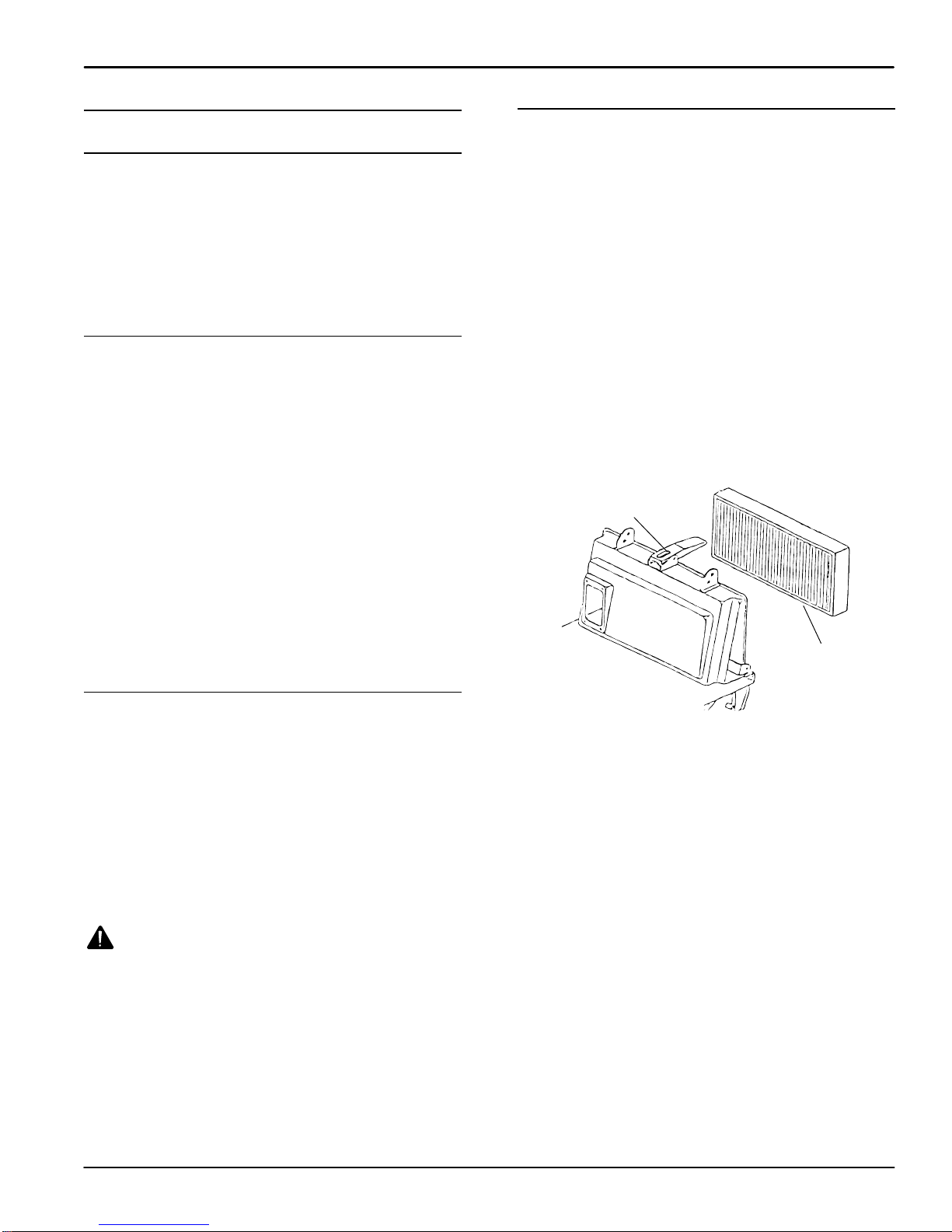
1. Press and release the filter shaker lever. The
lever operates a rod that will unclog the filter.
Repeat this operation 5 or 6 times (Figure 3).
2.Apart from the filter shaker, it is advisable every
now and again to remove the machine’s filter and
clean it out with a blast of air or a vacuum cleaner.
For this purpose, the filter is removed as follows:
a.Unlatch and turn rear bin latches inward.
b.Remove the rear bin.
Filter
Filter Shaker
Lever
FIG.3.
c. Unlatch filter lock latches, turn half moon
retainers away from filter.
d.Remove the filter while pressing the filter
shaker lever (Figure 3).
e.To remount the filter, carry out the operation in
reverse order.
NOTE: The filter features an arrow that shows you the
direction in which it should be fitted.
DUSTY ENVIRONMENTS: If you are using the
machine in a particularly dusty environment (cement
factories, sawmills, marble processing factories), it is
wise to use the filter shaker more frequently.
3.Every 200 hours of work, the filter must be
replaced. Follow the operations listed in step 2.
After the filter has been remounted, make sure the
gasket and filter are dust tight.
ATTENTION: Waste must be disposed of strictly in
accordance to the law.

OPERATION
8Tennant3620 (01–02)
REPLACING AND ADJUSTING THE SIDE BRUSH
FOR SAFETY: When servicing machine,
disconnect battery connections before working on
machine.
To Replace Side Brush:
1.Lift the front part of the machine.
2.Slacken the brush fixing screw and remove the
brush.
3.Replace the brush and secure the new one in
place with the screw and its washer.
To Adjust Side Brush:
1.The side brush is adjusted by loosening two
screws (Figure 4).
2.Position the brush using screw slots to adjust
required height. Once you have positioned it,
tighten the two screws.
Adjustment
Screws
FIG.4.
REPLACING AND ADJUSTING THE MAIN BRUSH
FOR SAFETY: When servicing machine,
disconnect battery connections before working on
machine.
To Replace Main Brush:
1.Remove the front waste bin and slacken the four
fixing screws to remove the brush.
2.When mounting a new brush, pay attention to the
direction in which the brush will spin; it must direct
dirt toward the center of the machine.
To Adjust Main Brush Height:
1.Remove the upper cover.
2.Loosen the knurled lock nut below the adjustment
handle and turn handle in the direction desired
(counterclockwise to increase pressure).
(Figure 5)
3.If brush is properly adjusted, bristles should bend
slightly against the cleaning surface (1/4”
penetration). Retighten knurled lock nut after
achieving proper adjustment.
FIG.5.
REPLACING AND ADJUSTING THE BELTS
FOR SAFETY: When servicing machine,
disconnect battery connections before working on
machine.
To prepare the machine for belt replacement:
1.Remove the upper cover and the front waste bin.
2.To replace or adjust drive belt: Remove the left
wheel, bumper, side guard and belt pulley cover.
To replace side brush belt: Remove the right
wheel, bumper and side guard.
3.With the machine dismantled in such a manner,
proceed to the following replacement instructions.

OPERATION
Tennant3620 (01–02)9
To Replace the main drive belt:
1.Remove belt from the pulleys.
2.Replace the belt. Position belt to the right side of
the belt tightener roller (Figure 6).
FIG.6.
To Replace the side brush belt:
1.Remove belt from main pulley. Remove fixing pin
and let the hooks of side arm come out of the idle
toothed ring (Figure 7).
2.Remove belt from machine.
3.Replace the belt. Hook side arm to the idle
toothed ring. Tighten fixing pin.
4.Place belt on main pulley.
FIG.7.
REPLACING THE FLAPS
FOR SAFETY: When servicing machine,
disconnect battery connections before working on
machine.
To Replace Outer side flaps 1 (Figure 8):
1.Remove the rear wheels and the appropriate side
guards.
2.Loosen the screws that secure the flaps to frame
2 and replace the old flaps with new ones.
2
3
1
5
1
2
4
3
6
5
FIG.8.
To Replace Inner side flaps 5 (Figure 8):
1.Lift the front part of the machine and loosen
screws 6 that secure the flaps to the frame.
2.Replace the old flaps with new ones.
To Replace Center flaps (Figure 8):
1.Remove the rear wheels and the appropriate side
guards.
2.Remove the rear door.
3.Loosen the two flap fixing pins 3, located on the
sides of the frame.
4.Grasp flap 4 and pull it outwards.
5.Remount the flaps in the same direction in which
they are removed.
6.Insert the two references in their holes.
7.Tighten the two fixing pins.

OPERATION
10 Tennant3620 (01–02)
REPLACING THE TRACTION CABLE
FOR SAFETY: When servicing machine,
disconnect battery connections before working on
machine.
To remove the traction cable:
1.Remove the upper cover of the machine.
2.Loosen the security dowel located on the cable
fixing pin.
3.Pull the cable out of the fixing pin and remove the
adjusting screw mounted on the handle.
4.Press the handle and pull the cable out of its
sheath.
To remount the traction cable:
1.Fit one end of the cable into the adjustment screw
of the handle (i.e. the end without the blocking
ball).
2.Insert the cable into its sheath.
3.Hook the blocking ball to the handle.
4.Slot the cable through the turned adjustment
screw secured to the machine frame and then
through the fixing pin.
5.Tighten the security dowel. The position of the
cable is adjusted by acting on the two adjustment
screws.
To Replace the side brush lifting cable:
1.Remove the upper cover and the front waste bin
of the machine.
2.Remove the front bumper, the right wheel and the
right hand side guard.
3.Loosen the cable clamp.
4.Loosen the security dowel on the fixing pin.
5.Remove the handle from the support and open it
up.
6.Pull the cable out of the two sheaths.
To remount the side brush lifting cable:
1.Put the cable inside the handle.
2.Close up the handle and fix it to its support.
3.Insert the cables into their sheaths.
4.Secure one end of the cables in place with the
clamp and the other end with the fixing pin. The
position of the cable is adjusted by acting on the
two adjustment screws.
REPLACING THE FAN MOTOR
To replace the fan motor:
1.Remove the upper cover.
2.Disconnect the battery cables and take the battery
out of the machine.
3.Disconnect the power supply cords of the motor
from the plug.
4.Remove the stop for the cable holder from the
motor.
5.Loosen the four motor fixing screws. Replace the
motor by carrying out the above operations in
reverse order:
NOTE: Make sure the motor is mounted level with the
fan.
ATTENTION: When connecting the motor respect
the polarity.
RECOMMENDEDSTOCK ITEMS
Refer to the Parts List section for recommended stock
items. Stock Items are clearly identified with a bullet
preceding the parts description. See example below:

OPERATION
Tennant3620 (01–02)11
TROUBLE SHOOTING GUIDE
PROBLEM CAUSE SOLUTION
The machine does not
move forward. Drive belt is broken. Replace belt.
The main brush is not The motor has burnt out. Replace motor.
spinning. A wire is detached. Repair connection.
The side brush is not spin-
ning. The belt is broken. Replace belt.
The battery does not stay The liquid is insufficient. Add liquid.
charged. The terminal is loose. Tighten terminal.
Dust comes out of the fan. The filter is broken. Replace filter.
The filter is in the wrong position. Position correctly.
The gaskets are worn. Replace gasket.
The brushes wear out too
quickly.The brushes are too low.Adjust brush height.
Dust forms during opera- The flaps are worn. Replace flaps.
tion. Clogged filter.Cleaning required.
The suction motor does The motor has burnt out. Replace motor.
not work. The wire is disconnected. Repair connection.
The machine does not The battery terminals are disconnected. Reconnect terminals.
turn on. The battery is discharged. Recharge battery.

OPERATION
12 Tennant3620 (01–02)
SPECIFICATIONS
Model: 3620
MAXIMUM WIDTH WITH SIDE BRUSH 810 mm (32 in)
MAXIMUM LENGTH WITH SIDE BRUSH 1160 mm (45.6in)
MAXIMUM HEIGHT WITH SIDE BRUSH 1000 mm (39.3in)
ACTUAL CLEANING WIDTH (MAIN BRUSH) 520 mm (20.5in)
WEIGHT 88Kg (194 lbs)
WEIGHT OF BATTERY24.9Kg (55 lbs)
CAPACITY OF FRONT WASTE BIN 32L (1.1 cu.ft)
BATTERY RUN TIME 2.5 h
FILTERING SURFACE 690 mm ( 27 in)
PRODUCTIVITY 26,900 sq. ft../2500m2per hour
INSTALLED POWER 360W/28A
BATTERY TYPE 12V, 105A
NOISE LEVEL AT OPERATOR’S EAR 77.2 dB(A)
VIBRATIONS 2,5 m/Sec2

WIRING DIAGRAM
12V ELECTRICAL DIAGRAM
Tennant 3620 (01-02)13
SW.1: KEY SWITCH
SW.2: FAN SWITCH
PG.1: BATTERY HARNESS PLUG
PG.2: BATTERY CHARGER PLUG
BAT : 12V BATTERY
CMF.1: PLUG
CMF.2: PLUG
M 1:MAIN BRUSH MOTOR
M 2:TRACTION MOTOR
M 3:SUCTION FAN MOTOR
F.x: FUSES
L 1: BATTERY LEDS
L 2: FAN INDICATOR LED
L 3: POWER INDICATOR LED
SW.1: KEY SWITCH
SW.2: FAN SWITCH
PG.1: BATTERY HARNESS PLUG
PG.2: BATTERY CHARGER PLUG
BAT : 12V BATTERY
CMF.1:PLUG
CMF.2:PLUG
M 1: MAIN BRUSH MOTOR
M 2: TRACTION MOTOR
M 3: SUCTION FAN MOTOR
F.x: FUSES
L 1: BATTERY LEDS
L 2: FAN INDICATOR LED
L 3:POWER INDICATOR LED
++
++
---
-

PARTSLIST
14 Tennant 3620 (01-02)
CHASSIS GROUP
20 19
17
3
3
18
21 22
16
8
13
3
10
13
4
6
4
42
14
16
3
15
13
23
9
13 4
6
5
4
4
14
1
2
7
11
12

PARTS LIST
CHASSIS GROUP
Tennant 3620 (08-02)15
Ref.Part No. Description Qty.Ref.Part No. Description Qty.
603346 Coverupperblue 1 12 610752 Wallbumpers,left complete 1
1 611912 Coverupperteal1 13 603349 Screw handlebar8
2 603348 •Screw,Thumb2 14 140028 Washer8X17 2
3 604214 NutM84 15 604223 Frame 1
4 604215 TEK locking 4 16 604224 Screw 8x10 8
5 604216 Handgrip1 17 603343 Cover,rightside 1
6 604217 •Handle cover rubber 2 18 603344 Cover,leftside 1
7 611922 Tennantlogo label1 19 603345 Cover,front1
613248 Hopperassembly, blue
8 613247 Hopperassembly, teal121604226NutM62
9 604221
•Gasket reinforced1,5m 22 604227 Foot20x9 M6x18 2
10 604218 Handlegrey cable casing 1 23 604228 Black,back drawer1
11 604627 Wallbumpers,rightcomplete 1
•RECOMMENDEDSTOCK ITEMS
20604225Screw8x162
1

PARTS LIST
ELECTRICAL/FILTER GROUP
16
Tennant 3620 (01-02)
OPTIONAL OPTIONAL
17
3636
17
3333
3838
99
3131
88
3232
3535
3434
77
3030
1414
4040
26
2727 264242
2828
3131
3030
3131 30
3030
30
2929
3131
3232
88
3939
23
2222
23
2929
2525
2424
2626
21
1212
21
3232
1313
1010
1111
3131
22
66
2020
1919
3737
4444
66
44
11
4343
5522
16
16
4545
1818
4141
33
1616
1515
BATTERY
CONTROL
SYSTEMSYSTEM
CONTROL
BATTERY
44
44
66
77

PARTS LIST
ELECTRICAL/FILTER GROUP
Tennant 3620 (01-02) 17
Ref. Part No. Description Qty. Ref. Part No. Description Qty.
1 604183 Platedashboard 124 604202 Ringinner snap ∅16 1
603360 Key withignition(2) 125 604203 Bar articulate 12
606197 •Keyreplacement 126 604204 Screw M10X6 2
3 604184 Switch bipolar 127 604205
•Flapbackside1
4 604185 Screw 5X20 228 612622
•Flapright side 1
5600012000 Red batt.Charger connector 129 612623 •Flapinner 2
6604213 Nut M5 830 604208 Screw 3.5X9.5 16
7 612617
•Flapleftside 131 604209 Screw 8
8612618 Washer 5X15 232 604210 Nut M4 8
9604190 Batterycontainer 133 603361 Clamp guard front1
10 612619 Screw 6X16 134 603362
•Guard,front rubber1
11 604192 Lever filtershaker 135 603363
•Skirt,hopper 1
12 604193 Rail filtershaker 136 603342 Board circuit main 1
13 603358
•Fuse30A 337 604212 Hourmeter LCD 1
14 604194 Fuse box +cover 138 612624 Batterystrap 1
15 612620 Nut M8 239 612625 Batterytray 1
16 610753 Handle, filter lock240 130059 •Fuse20A centralbrush 1
17 607586
•Filterhospitalgrade 141 609971
•Kit, pre-filter 1
18 603359
•Gasket,filter142 604187
•Adhesivefront drawer1
19 612621
•Insulation electrical 143 600013000 Black batt. charger connector 1
20 604198 Nut M18 1578426 Battery, wet filled 1
21 604199 Spring filtershaker 1
44
611867 Optional Battery, gel 1
22 604200 Gasket OR102 1609960 Charger 120V for wet filled 1
23 604201 Pin 1
45
611866 Optional charger 120V for gel 1
•RECOMMENDEDSTOCK ITEMS
610754 Wire harness,
600988 Terminal, battery 1
quick connect 1
cable
46
47

24
81
76
74
72
67
69
66
68
51
5
29
49
46
73
48
29
71
75
45
1568
45
67
40
70
28
80
79 31
38 37
40
36
39
54
63
65
64
47
44
61
59
56
3
64
78
58
57
60
632
27
48
12
55
11
14
3
53
19
62
29
32
32
35
33
31
37
39
36
34
33
32 24
50
14
38
42
13
13
41
43
20
13
8
18
7
25
6
77 31
30
1
26 17
25
9
52
2
4
4
2322
21
16
14
1511
12
13
3
10
4
82
82
4
10
3
13
12
11
15
14
16
21
22 23
4
4
2
52
9
25
17
26
1
30
3177
625
7
18
8
13
20
43
41
13
13
42
38
14
50
24
32
33 34
36
39
37
31
33
35
32
32
29
62
19
53
3
14
11
55
12
48
27
32
6
60
57
58
78
64
3
56
59
61
44
47
64
65
63
54
3936
40
37
38
31
79
80
28
70
40
67
45
6815
45
75
71
29
48
73
46
49
29
5
51
68
66
69
67
72
74
76
81
24
PARTS LIST
BRUSH GROUP
18
Tennant 3620 (01-02)

PARTS LIST
BRUSH GROUP
Tennant 3620 (01-02) 19
Ref. Part No. Description Qty.Ref. Part No. Description Qty.
1 612631 Sheath side brush 1 41 604149 Outer snapring∅12 1
2 612632 Handle, drive 1 42 604150 Brush adjfix pivot1
3 604105 Adjusterturner ∅7 3 43 604151 Bracket brush adjustment 1
4 612633 Lever, sidebrushdrive 1 44 604152 Washer side armfeet 2
5 140272 Screw M6x16 1 45 604153 Bearing HK1012 2
6 604107 Washer 6x12 6 46 604154 Screw 8X10 2
7 604108 Handwheel ∅60 12X67 1 47 604155 Spacer side brush shaft 1
8 604109 Nut ring ∅40 M12 1 48 612620 Nut M8 2
9 612634 Sheath drive cable 1 49 604157 Pulley 1
10 612635
•Cable drive 1 50 604158 Motor,brush drive 1
11 604112 Dowel 5X6 2 51 604159 Washer M6X24 1
12 604113 Screw wire fixing 2 52 612638 Casing, sidebrush cable 1
13 604114 Washer M8X17 7 53 612639
•Cable sidebrush lift 1
14 604115 Nut block M8 3 54 604160 Pin 17X34 1
15 604116 Screw 8X25 3 55 604161 Clamp∅7 1
16 604117 Bushing, lever belttightner 1 56 604162 Screw 8X22 1
17 604118 Spring Traction 1 57 604163 Brush lift lever 1
18 604119 Belttightner roll 1 58 604164 Washer 8X32 1
19 604120 Belttightner roll H15 1 59 604165 Ring brush bearing 1
20 604121 Bearing 608 2RS 1 60 604166 Balls 11/32” 6
21 604122 Ring, snap, ∅22 inner1 61 604167 Ring brush tooth 1
22 604123 Spacer 1 62 604168 Key 3X3,7 1
23 604124 Braket beltlight 1 63 604169 Bushingbearings 1
24 604125 Pinrocker 2 64 604170
•Bearing6005 2RS 2
25 604126 Bushingrocker 2 65 604171 Ring idle tooth 1
26 604127 Rocker 1 66 604172 Ringout snap ∅25 1
27 604128 Nut block M6 6 67 612640 Washer nylon 2
28 612636 Screw 12X60 1 68 604174 Spacer 2
29 604130 Wheel support ∅100 1 69 604175 Pulley∅27X15 1
30 611906 Screw 6X16 3 70 612441
•Beltside brush 1
31 604140 Screw 5X70 4 71 604176 Washer M8X24 2
32 604141 Nut M5 4 72 604177 Support brushside 1
604302 •Brushsetmain 1 73 604178 Flange brushdrag 1
604624 •Brush,main,white (Stiff)set 2 1 603337
•Brushside 1
33
604625 •Brush,main,brass set2 1
74
604626 •Brushsidestiff1
34 604142 Brush shaft 1 75 604179 Pulley∅30X1 1
35 604143 Key 5X5X15 1 76 604180 Screw 6X10 3
36 604144 Spacer, brush shaft2 77 604139 Screw 6X20 3
37 604145 Pin,dowel 6X5 2 78 604082 Bearing HK1412 1
38 612637 Support bearing 2 79 612642 Spacer 16mm 1
39 604147
•Bearing6202 2RS 2 80 604173 Nut block M12 1
40 604148 Ringout snap ∅15 3 81 612643 Screw 8X35 1
82 604208 Screw 3,5X10 1
•RECOMMENDED STOCK ITEMS
*
50A612644 Gearonly,brushmotor1
*

PARTSLIST
20 Tennant3620 (01–02)
DRIVE GROUP
25
14
8
49
12
11
9
12 12
32
10
11
32
356
7
1
24
10
13 30
29
19
27
31
24 23
5
7
17
1
642
3
18
16
15
21
22
2019
4
28
33
26
35
36
34
8
Table of contents
Other Tennant Blower manuals

Tennant
Tennant 365 User manual

Tennant
Tennant S30 Training manual

Tennant
Tennant 800 User manual

Tennant
Tennant S30 User manual

Tennant
Tennant M17 Series Training manual

Tennant
Tennant 6400 User manual

Tennant
Tennant S3 Product manual

Tennant
Tennant S880 User manual

Tennant
Tennant 9014819 Product manual

Tennant
Tennant sentinel User manual

Tennant
Tennant 6500 User manual

Tennant
Tennant sentinel User manual

Tennant
Tennant SweepSmart S20 ELECTRIC Training manual

Tennant
Tennant 6550 User manual

Tennant
Tennant 3640E User manual

Tennant
Tennant 250 Product manual

Tennant
Tennant 285 User manual

Tennant
Tennant A60 User manual

Tennant
Tennant 6100 Training manual

Tennant
Tennant 614214 Product manual