manuals.online logo
Brands
  1. Home
  2. •
  3. Brands
  4. •
  5. Tennant
  6. •
  7. Floor Machine
  8. •
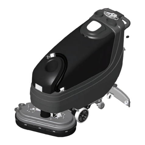
  9. Tennant IRIS T300 User manual

Tennant IRIS T300 User manual

Other manuals for IRIS T300

4

Other Tennant Floor Machine manuals

Tennant ReadySpace R14 Operating and installation instructions

Tennant

Tennant ReadySpace R14 Operating and installation instructions

Tennant 1186E User manual

Tennant

Tennant 1186E User manual

Tennant 3530 Product manual

Tennant

Tennant 3530 Product manual

Tennant 2510 Product manual

Tennant

Tennant 2510 Product manual

Tennant T5 Operating and installation instructions

Tennant

Tennant T5 Operating and installation instructions

Tennant 6080 Training manual

Tennant

Tennant 6080 Training manual

Tennant B10 Operating and installation instructions

Tennant

Tennant B10 Operating and installation instructions

Tennant 242E User manual

Tennant

Tennant 242E User manual

Tennant 750 User manual

Tennant

Tennant 750 User manual

Tennant 96GR User manual

Tennant

Tennant 96GR User manual

Tennant 5700XP User manual

Tennant

Tennant 5700XP User manual

Tennant R3 ReadySpace User manual

Tennant

Tennant R3 ReadySpace User manual

Tennant 186 User manual

Tennant

Tennant 186 User manual

Tennant EX- SC- 716 User manual

Tennant

Tennant EX- SC- 716 User manual

Tennant 5680 User manual

Tennant

Tennant 5680 User manual

Tennant 1240 User manual

Tennant

Tennant 1240 User manual

Tennant 608808 Product manual

Tennant

Tennant 608808 Product manual

Tennant S5 User manual

Tennant

Tennant S5 User manual

Tennant 1200 611468-230V User manual

Tennant

Tennant 1200 611468-230V User manual

Tennant 1071121 Product manual

Tennant

Tennant 1071121 Product manual

Tennant EX-SC-1530 User manual

Tennant

Tennant EX-SC-1530 User manual

Tennant EC2 Product manual

Tennant

Tennant EC2 Product manual

Tennant 8410 User manual

Tennant

Tennant 8410 User manual

Tennant M20 User manual

Tennant

Tennant M20 User manual

Popular Floor Machine manuals by other brands

Nilfisk-Advance Advance SC370 17B Instructions for use

Nilfisk-Advance

Nilfisk-Advance Advance SC370 17B Instructions for use

BETCO PB24 Operator's manual

BETCO

BETCO PB24 Operator's manual

Numatic ET 4045 Owner's instructions

Numatic

Numatic ET 4045 Owner's instructions

Mytee 8070 Mytee-Lite instructions

Mytee

Mytee 8070 Mytee-Lite instructions

Kärcher B 140 R manual

Kärcher

Kärcher B 140 R manual

Nilfisk-Advance SW 750 Service manual

Nilfisk-Advance

Nilfisk-Advance SW 750 Service manual

IPC CT51-71 BT quick guide

IPC

IPC CT51-71 BT quick guide

Tornado Marathon 2000 98190 Operation & maintenance manual

Tornado

Tornado Marathon 2000 98190 Operation & maintenance manual

Windsor ADMIRAL Admiral 8 Specifications

Windsor

Windsor ADMIRAL Admiral 8 Specifications

Numatic TTB 1117/100 Owner's instructions

Numatic

Numatic TTB 1117/100 Owner's instructions

Nobles Frontier Operator and parts manual

Nobles

Nobles Frontier Operator and parts manual

lavina 21-X user manual

lavina

lavina 21-X user manual

KENT Edge 28B Service manual

KENT

KENT Edge 28B Service manual

Windsor BDP 51/2000C operating instructions

Windsor

Windsor BDP 51/2000C operating instructions

Nilfisk-Advance Warrior 34RST How-to guide

Nilfisk-Advance

Nilfisk-Advance Warrior 34RST How-to guide

HAWK ENTERPRISES HP1513-180BRUTE manual

HAWK ENTERPRISES

HAWK ENTERPRISES HP1513-180BRUTE manual

Triple S Ace 26T1 user guide

Triple S

Triple S Ace 26T1 user guide

Nobles 612215 - 2401 Operator and parts manual

Nobles

Nobles 612215 - 2401 Operator and parts manual

manuals.online logo
manuals.online logoBrands
  • About & Mission
  • Contact us
  • Privacy Policy
  • Terms and Conditions

Copyright 2025 Manuals.Online. All Rights Reserved.

KIT NO. 9014676- USA, 9014101- International Page1of9
9014180 Rev. 03 (01- 2017) Tennant Company www.tennantco.com
T300 IRIS Telemetry Kit
This kit includes the necessary parts to install IRIS telemetry technology on a standard T300 model.
INSTALLATION INSTRUCTIONS:
Installation Time: 1.5 Hours
Kit Installation Requirements:
- Tennant ServiceLink computer or a computer with Wi-Fi
connection to access the Tennant Service Application
Software, and USB cable (supplied with kit).
Computer System Requirements: Windows

7OS,
Microsoft .NET Framework 4.5 or later, USB Port.
- The IRIS Telemetry Kit MUST be activated to complete
installation. After kit is installed CALL Technical Support to
activate as described on page 6.
Special Tools Required: T-25 torque screwdriver
PREPARE MACHINE FOR KIT INSTALL:
1. Drain the solution and recovery tanks.
2. Park the machine on a level surface and remove key.
3. Disconnect battery cables from battery pack. If model
is equipped with the red quick disconnect connector,
disconnect connector (Figure 1).
NOTE: If model is equipped with the optional battery
lift-out tray, the batteries and tray must be removed from
machine to allow space to replace the circuit board.
WARNING: Always disconnect battery cables
from machine before working on electrical
components.
Models with battery
cable connectors
Fig. 1
4. Cut the three cable-ties that secure the vacuum hose,
drain hose, and battery cables to the heat- sink panel
(Figure 2).
Cable-Ties
Cable-Tie
Fig. 2
5. Remove the top two screws from the heat-sink panel
and carefully lower panel as shown (Figure 3). Place a
piece of cardboard over the battery terminals to prevent
contact with metal heat-sink panel.
FOR SAFETY: When servicing machine, keep all
metal objects off batteries.
Fig. 3
6. Disconnect wire connections and remove circuit board
from the heat-sink panel (Figure 4). The circuit board
is mounted to panel with eight torque head screws
and five standoffs. Squeeze standoff flange to release
circuit board from panel.
Standoff Heat-sink
Panel
Fig. 4
Page2of9
KIT NO. 9014676- USA, 9014101- International
9014180 Rev. 03 (01- 2017) Tennant Company www.tennantco.com
INSTALL TELEMETRY CIRCUIT BOARD, SIM
CARD AND ANTENNA:
1. Use the supplied static ground strap as instructed
when handling new circuit board (Figure 5).
Fig. 5
2. Carefully remove the telemetry SIM card from the card
holder (Figure 6).
NOTE: DO NOT dispose the card holder, the bar-code
information will be needed to activate the telemetry
system as described later to complete installation.
SIM
card
USA SIM Card
(Yellow)
International SIM Card
(White)
Card holder
SIM
card
Card holder
Kit 9014101
Kit 9014676
Fig. 6
3. Fully insert the SIM card into the circuit board card slot
as shown (Figure 7).
Clipped
Corner
SIM
Card
Slot
SIM Card
Fig. 7
4. Mount the new circuit board to the heat-sink panel
using existing hardware (Figure 8). Install the antenna
bracket with two spacers as shown. Reconnect the five
wire harness connectors to new circuit board.
Antenna
Bracket and
two Spacers
Fig. 8
5. Reconnect the bus-bar and red battery cable to new
circuit board. To allow clearance to remount panel to
machine, position the wires that are connected to the
stand-off as shown (Figure 9).
Red
Cable
Position wires
as shown
Stand-off
Bus-bar
Stand
-off
9Nm
6.6 lb-ft 3.9 Nm
2.9 lb-ft
Fig. 9
6. Connect the new circuit board’s antenna wire to the
antenna bracket as shown (Figure 10). Then connect
the antenna wire to circuit board wire as shown .
Fig. 10
Page3of9
KIT NO. 9014676- USA, 9014101- International
9014180 Rev. 03 (01- 2017) Tennant Company www.tennantco.com
7. Adhere the cable clip to machine as shown. Secure
antenna wire within clip. Using two cable clamps and
two shelf-tapping screws, mount the antenna to
machine as shown (Figure 11).
Cable Clip
[575037] Cable
Clamp
[140916]
Screw
[1018155]
Antenna
Wire
Fig. 11
8. Re-install the heat-sink panel to machine. Make sure to
reconnect ground wire to panel (Figure 12).
Ground Wire
Fig. 12
9. Reconnect cables, vacuum hose and drain hose to the
heat-sink panel with cable-ties (Figure 13).
Cable-Tie
[130773] Cable-Tie
[130773]
Fig. 13
INSTALL AM II BATTERY CHARGER
COMMUNICATION ADAPTOR HARNESS:
Diode Plug
[222290]
Adaptor Harness
[1075195]
1. Remove the two lower torque screws at bottom of
control console and carefully lower the console cover
as shown (Figure 14).
Fig. 14
2. Remove the two upper torque screws from bezel
assembly and lower bezel (Figure 15)
Fig. 15
3. Disconnect the large harness connector from control
board and route the connector down through harness
opening as shown (Figure 16).
Fig. 16
Page4of9
KIT NO. 9014676- USA, 9014101- International
9014180 Rev. 03 (01- 2017) Tennant Company www.tennantco.com
4. Plug the adaptor harness into the routed connector.
Plug the diode, supplied with kit, into adaptor harness
as shown (Figure 17)
Adaptor
Harness
Diode
Fig. 17
5. Route the adaptor harness up through the harness
opening and connect to control board (Figure 18)
Adaptor
Harness
Fig. 18
6. Replace the bezel and the lower console cover
(Figure 19).
Fig. 19
7. Reconnect battery cables to battery pack (Figure 20).
Models with battery
cable connectors
Fig. 20
8. Apply the FCC label to machine as shown (Figure 21).
Fig. 21
9. See TENNANT SERVICE APPLICATION SOFTWARE
to reconfigure the machine’s control board to
recognize the IRIS Telemetry installed kit.
Page5of9
KIT NO. 9014676- USA, 9014101- International
9014180 Rev. 03 (01- 2017) Tennant Company www.tennantco.com
TENNANT SERVICE APPLICATION
SOFTWARE:
The Tennant Service Application Software is required to
reconfigure the machine’s control board to recognize the
IRIS Telemetry installed kit. The software can be
accessed or installed as described in this section.
NOTICE: If the Service Application Software is currently
installed on your computer, confirm or re-install the software
to ensure latest software version is installed.
IMPORTANT: This kit requires the following firmware
revisions or higher to activate the AM II charger interlock
feature (Figure 22).
Images from the Service Diagnostics Software Application
LCD Model
Membrane Model
Fig. 22
To confirm the firmware versions for models equipped with
LCD displays, go to the “About” screen as shown below
(Figure 23). If the User Interface and Scrub controller
firmware revisions are less than specified below, Service
Application software update may be required to update
firmware revisions. For models with membrane panels,
the Service Application software is required to confirm
firmware version as shown above.
Fig. 23
For Tennant service personnel equipped with
ServiceLink computers, the software is pre-installed on
your computer as described below.
The software application is titled “Service Diagnostics”.
(Figure 24).
Icon on
Desktop
From Start menu
From Start menu > All Programs > Tennant Company >
Tennant Service Diagnostics
Fig. 24
Page6of9
KIT NO. 9014676- USA, 9014101- International
9014180 Rev. 03 (01- 2017) Tennant Company www.tennantco.com
For other Service Groups,the Service Application
Software can be downloaded from the “My Tennantt”
website as described below.
1. Go to www.tennantco.com and click on the “My
Tennant Customer Sign In” tab in the upper left
corner (Figure 25).
Fig. 25
2. Log on to the “My Tennantt” website or register as a
new user (Figure 26).
Fig. 26
3. Once logged on to the “My Tennantt” website, click
on the “Service Application Software” link under
the “Product Support & Solution” section as shown
below (Figure 27).
Fig. 27
5. Within the Service Application Software page, click on
the link titled “Service Diagnostics...” to download
the application installer (Figure 28). Click the Save
button.
Fig. 28
6. Open the “Downloads” folder and locate the
“Firmware_setup” zip file. Open the zip file and click
on the “setup” file to install the application software on
your computer (Figure 29).
Fig. 29
7. After the application software is installed on your
computer, refer to figure 24 to access the program.
Page7of9
KIT NO. 9014676- USA, 9014101- International
9014180 Rev. 03 (01- 2017) Tennant Company www.tennantco.com
REPROGRAM THE CONTROL BOARD:
The following Tennant Service Application Software is
required to reconfigure the machine’s control board to
recognize the IRIS Telemetry installed kit.
See TENNANT SERVICE APPLICATION SOFTWARE
for further details.
1. Start the Service Software Application program
“Service Diagnostics SE...”(Figure 30).
Icon on
Desktop
Fig. 30
2. After start up, the following screen will appear
(Figure 31).
Fig. 31
3. Connect the USB cable to computer and to the USB
port on machine as shown. Turn the key switch to the
on position (Figure 32).
Fig. 32
4. The application software will then connect to the
machine (Figure 33). If the application remains on the
“Connecting to Machine...” screen for an extended
period, cycle key or close and restart the application
software. If it still fails to connect, restart the computer.
Fig. 33
5. Once connected, the home screen will appear (Figure
34). If firmware updates are required, the “Firmware”
button will be highlighted in yellow as shown. Press
the button to update the machine’s firmware.
Fig. 34
If the following screen appears, continue with the
firmware update by pressing the yellow “Update”
button(Figure35).
Fig. 35
Page8of9
KIT NO. 9014676- USA, 9014101- International
9014180 Rev. 03 (01- 2017) Tennant Company www.tennantco.com
6. From the Home screen, press the Configuration
button (Figure 36).
Fig. 36
7. From the machine configuration page, select “Yes”
from the IRIS drop-down menu to configure the
machine with telemetry technology (Figure 37). Then
press the down arrow button to program the machine.
A green check will appear next to the down arrow
button when programmed.
Fig. 37
7. Cycle the key to apply the new machine configuration.
Disconnect the USB cable.
ACTIVATE THE IRIS TELEMETRY SYSTEM
NOTE: The IRIS telemetry system must be activated
to complete this installation. The system will not
function until it is activated.
For assistance to activate the IRIS telemetry system, call
your customer service location:
Before calling, be sure to have the machine serial number
and the 20 digit SIM card bar-code number ready for
activation (Figure 38).
USA Customer Service Location: Call Technical
Support between hours 7:00 am and 5 pm CST, Monday
through Friday.
Australia Customer Service Location: Call CCC
between hours 8:00 am and 5 pm AEST, Monday through
Friday. Ask to be routed to the IRIS expert for assistance.
Canada, Europe, Middle East, Africa Customer
Service Location: Call local IRIS expert between hours
8:00 am and 5 pm, Monday through Friday.
Machine
Serial
Number
International
SIM Card
Bar-Code
Number
USA SIM
Card
Bar-Code
Number
Fig. 38
Page9of9
KIT NO. 9014676- USA, 9014101- International
9014180 Rev. 03 (01- 2017) Tennant Company www.tennantco.com
T300 IRIS Telemetry Kit Parts List
3
4
5
7
1
2
6
8
9
10
14

13
11
12
Ref. Part No. Description Qty.
9014101 Telemetry Kit, IRIS, International, Di [T300] (Complete Kit) 1
9014676 Telemetry Kit, IRIS, USA, Di [T300] (Complete Kit) 1
11215340 Circuitboard, Assy [Vw, Cntrl, Telem] 1
21074365 Controller, Telem [SIM Card, White, Intl., M2m- air] (included in Kit 9014101) 1
21074364 Controller, Telem [SIM Card, Yellow, USA., M2m- air] (included in Kit 9014676) 1
3315724 Cs, Antenna, Telem, 18.0 In [Gprs] 1
4140916 Clamp, Cable, Nyl, 0.62d, Nat 2
51018155 Screw, Pan, Phl, M5 X 0.80 X 16, Tcut,Ss 2
6575037 Clip, Cable [quick lock] 1
7130773 Tie, Cable, Nyl, 11.0L, .14W, 3.0 Max. D 3
81071235 Cable, USB 1
927964 Strap, Ground, Static 1
10 1069580 Label, Machine, Telem [FCC, USA,INTL] 1
11 1227812 Bracket, SMA Connector [Antenna] 1
12 1227815 Spacer, Unthreaded, Alum. [Bracket] 2
13 1075195 Harness, Ele, Adaptor, AM II 1
14 222290 Diode, Ele,Plug 1