Tennsco 1471 Instruction Manual
PK-1751211
ASSEMBLY INSTRUCTIONS & PARTS MANUAL #1751211
Tennsco Corp., Dickson, TN 37056-1888 • (615) 446-8000
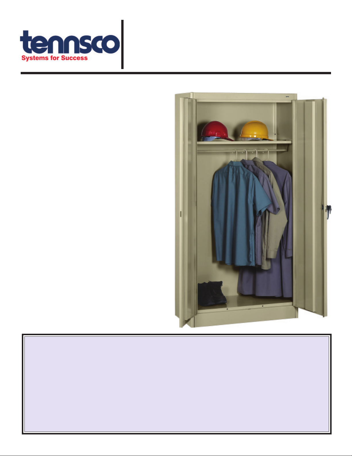
TENNSCO WARDROBE CABINET
Model 1471
LIMITED WARRANTY
Tennsco warrants goods purchased hereunder to be free of defects in materials and workmanship for a period of one (1) year from the date of shipment, hereunder.
This warranty shall not apply in the event goods are damaged as a result of misuse, abuse, neglect, accident, improper application, modification or repair by persons
not authorized by Seller, where goods are damaged during shipment, or where the date stamps on the goods have been defaced, modified or removed. UNLESS
CONSIDERED UNENFORCEABLE OR UNLAWFUL UNDER APPLICABLE LAW:
a. ALL IMPLIED WARRANTIES, INCLUDING BUT NOT LIMITED TO WARRANTIES OR MERCHANTABILITY AND FITNESS FOR A PARTICULAR PURPOSE
AREHEREBYEXCLUDED:
b. BUYERS REMEDY, IF ANY, FOR ANY DEFECTIVE GOODS SHALL BE LIMITED TO A REFUND BY SELLER OR REPLACEMENT OF THE GOODS AT
SELLER’S OPTION, AND SHALL IN NO EVENT INCLUDE DAMAGES OF ANY KIND, WHETHER INCIDENTAL, CONSEQUENTIAL OR OTHERWISE.
NO GOODS ACCEPTED FOR RETURN WITHOUT PRIOR APPROVAL. Seller shall have the right to inspect any goods claimed to be defective at Buyers place
of business or require Buyer to return the goods to Seller for inspection on Seller’s premises. Transportation charges covering returned goods will be borne by
Seller only if such goods are proven to be defective, are covered by this warranty and are returned within the warranty period stated above.
TENNSCO Corp., P.O. BOX 1888, DICKSON, TN 37056-1888
(615) 446-8000 or (866) 446-8686 (toll free)
RETAIN INSTRUCTIONS FOR FUTURE REFERENCE!
Congratulations on your purchase of a
Tennsco Wardrobe Cabinet! Tennsco's 1471
units provide a level of quality you won't find
elsewhere. They provide secure storage with a
hanging rod for jackets, clothing, and other
hanging garments, along with one shelf for
hats, books, tools, and other general storage.
These cabinets also offer a locking chrome
handle with two keys, and a three-point locking
system for extra security.
Tennsco's cabinets are constructed from top
quality 22 to 24 gauge steel, with 22 gauge
steel shelves, offering weight capacities of up to
200 lbs. per shelf (evenly distributed). Our
attractive and durable powder-coated paint
finish will provide for years of service.
GENERAL SAFETY INFORMATION
Some parts may have sharp edges. CARE must
be taken when handling various pieces to avoid
injury. For safety, wear a pair of work gloves when
assembling or performing any maintenance on
your cabinet.
ASSEMBLY OF 1471 CABINETS
1. All reference numbers refer to the illustration on
the back cover. This is to help you to identify the
various parts as they are mentioned.
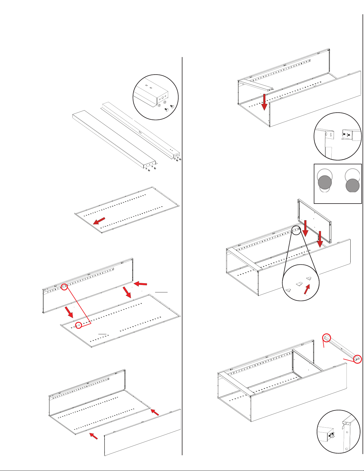
3. Place the
cabinet
back (Ref. No. 1)
on a protected surface to
prevent
scratching
the
paint. The
flange
on the bottom of
the back should be
facing upward.
5. Attach the right side (Ref. No. 3) to the back in
the same manner as you
did in step 4.
Make sure
that the
lances
on the
right side
are pointed in
the same direction
as those on the back and
the left side.
8. Locate the two keyhole-shaped slots on the top
front of each end-panel. Attach the header (Ref.
No. 5) in the same way you attached
the sill, by inserting the previously
attached loose bolt heads
into the large end
of the key-
hole
slots
(Inset D)
.
Position
by sliding
the bolts
securely into the
smaller
end of the
slots. Refer to Inset C
(in step 6 above) for improper and
proper
seating
of the boltheads. Tighten
the four nuts securely.
Flange faces upward
7. Insert
the shelf
(Ref. No. 4) into the top
position
on the
shelf adjustment strips.
Do this by inserting
the shelf edges
into the lances on all four strips.
Be sure
that the channeled edge
of the shelf is toward the
cabinet front. If a
lance is too
tight, it
may be
helpful to
use a
screwdriver
to SLIGHTLY
pry it open.
Two bolts
and nuts on
each side
Inset D
2. Prepare the header (Ref. No. 5) for
installation by inserting a bolt into
the two outside holes on
each end, as
shown in Inset A.
The center hole
should remain empty.
Loosely attach nuts to each bolt,
leaving enough slack so that
the bolt heads may later be insert-
ed into a slot. Prepare the sill (Ref.
No. 6) in the same way.
Sill
Header
Inset A
4. Attach the left side (Ref. No. 2) to the back by
placing flange (A) around the back and
bolting the pieces
together with
seven bolts
and
nuts
(Ref.
Nos.
18 &19).
Be sure that
the lances on
all shelf adjustment
strips (B) point in the same direction.
6. Locate the
two keyhole
-shaped
slots on the front of
each
end-panel
bottom.
Attach
the sill (Ref.
No. 6) by
inserting the
loose bolt heads
(which you attached
to the sill in step 2) into the large end
of the keyhole slots (Inset B). Position
by sliding the bolts securely into the
smaller
end of
the slots. Inset C at right
shows improper
and proper
seating of
boltheads.
Tighten the four nuts
securely.
Tools Needed: A free 11/32" nut driver is provided with each Tennsco cabinet (Ref. No. 19). In addition,
you will need a flathead screwdriver. A hammer is required to install the hinge pin and lock bar.
Two people recommended for assembly. Approximate assembly time: 15 to 25 minutes.
Inset B
Inset C
Improperly
seated
Properly
seated
AFlange goes
under back
BAll lances point UP
on both back
and side.

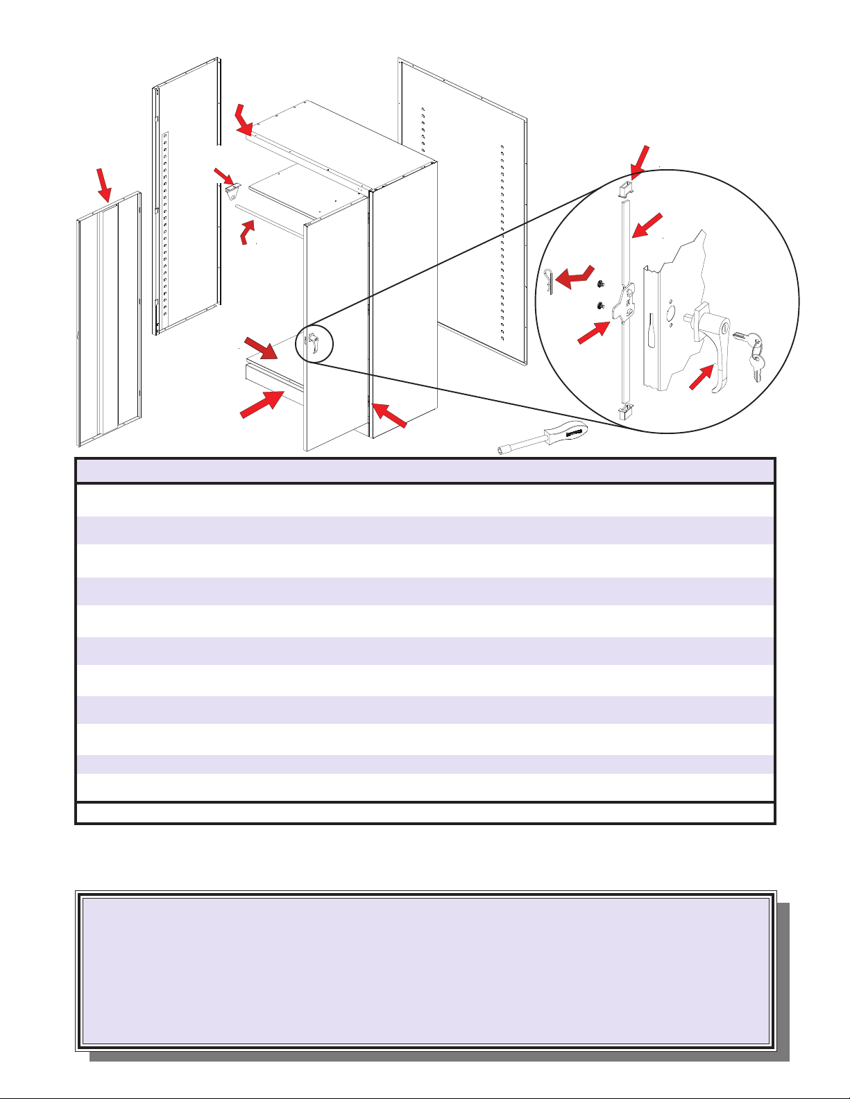
13. Attach the right door (Ref. No.
10) to the unit in the same
way you attached the left
door.
Handle/LockingSystemInstallationInstructions
4. Slide the nylon lock bar
guide inserts (Ref. No. 15)
over the lock bar ends and
through the door slots (see
"B" at right). Push firmly
until the guides snap into
place. If necessary, turn
the handle back to the
open position and gently
tap with a hammer until the
guides slide into place.
3. With the handle still in the open
position, hook the locking bars (Ref.
No. 11) to the locking cam (see "A" at
left). Once in position, slowly rotate the
door handle to the closed position so
the lock bars protrude from the holes
at the top and bottom of the door
(shown at right, below).
A
14. Instructions for attaching
the handle and locking
mechanism are given at
right.
9. Place the bottom (Ref. No. 7) in the bottom
lances of the
shelf adjustment
strips. The
flange with
two holes
should
face the
front, and
it should
hang over the
sill. Bolt to the
sill with two bolts and nuts.
10. Turn the
unit on its
side. Then,
attach the top (Ref. No. 8) by
sliding it under the sides and
header, with the flange
hanging over
the back.
Secure
with 14 bolts and nuts (three
along each side, four in the
back, and four along the front).
12. Attach the
left door
(Ref. No.
9) to the unit by placing the
door on the hinges,
aligning the
holes,
and using a hammer
to tap the hinge pins (Ref.
No. 16) into place
with the
side of a
screwdriver.
11. Set the unit upright and attach a coat rod bracket
(Ref. No. 18) beneath the left side of the cabinet
shelf by inserting one bolt through the hole in the
left edge of the shelf. Secure with
a nut. Attach the right bracket in
the same way. Then,
slide the coat rod
(Ref. No. 17) t
hrough
holes in the brackets
(Inset E.)
Inset E
Mount brackets by
attaching here with one
bolt and nut.
Top
goes
under
side flanges
Top tucks under
front flange
Insert shelf into
bottom lances.
Two holes must
be in front.
2. Turn the handle to
the open position, and
place the locking cam
(Ref. No. 13) over the square
shank of the door handle. The
latch must be facing down-
ward as shown. Then place the
locking cotter pin (Ref. No. 14)
through the hole of the
square shank as
shown at right.
1. Place the locking handle
(Ref. No. 12) on the right
hand door and fasten
with two #8-32 x 1/4"
slotted hex-head bolts
and lockwashers (Ref.
No. 17).
B
B
REPLACEMENT PARTS
TO OBTAIN PROPER REPLACEMENT PARTS, PLEASE PROVIDE THE FOLLOWING INFORMATION:
Model Number (1471) Purchase Date
Description of part(s) needed and part Your company name
number(s) as shown in Parts List (above) Contact person's name
Color (i.e. Medium Grey, etc.) Who the product was purchased from
Was item missing, or was it damaged?
Customer Service: (866) 446-8686 Fax: (866) 445-7260
If requesting parts by telephone, ask for customer service and have as much of the above information ready as possible.
Cotter Pin
(Ref. No. 14)
Right Side
(Ref. No. 3)
Sill
(Ref. No. 6)
Back Panel
(Ref. No. 1)
Locking Cam
(Ref. No. 13)
Locking Handle
with Keys
(Ref. No. 12)
Shelf
(Ref. No. 4)
Bottom
(Ref. No. 7)
Left Side
(Ref. No. 2)
Top
(Ref. No. 8)
Header
(Ref. No. 5)
Left Door
(Ref. No. 9)
Right Door
(Ref.
No. 10)
Locking Bar Guide
Nylon Insert
(Ref. No. 15)
Locking Bar Set
(Ref. No. 11)
Hinge Pin
(Ref. No. 16)
REF. NO. PART NO.
DESCRIPTION
1 Back panel 1 944BA
2 Left side 1 944LS
3 Right side 1 944RS
4 Shelf 1 301
5 Header 1 944HE
6 Sill 1 944SI
7 Bottom 1 944BO
8 Top 1 944TO
9 Left door 1 944LD
10 Right door 1 944RD
11 Locking bar set 1 944LB
12 Locking handle w/keys & hardware 1 944LH
13 Locking cam* 1 944LC
14 Cotter pin* 1 CTRPN
15 Locking bar guide insert (nylon)* 2 944GI
16 Hinge pin 6 944HP
17 Coat rod 1 045CR
18 Coat rod bracket 2 045RB
19 Tennsco nut driver 1 TOOL-2
20 #8-32 x 3/8"bolts* 50 AVAILABLELOCALLY
21 #8-32 nuts* 50 AVAILABLELOCALLY
*Included in Ref. No. 12, locking handle with keys and hardware (Part No. 944LH).
QTY.
Tennsco Nut Driver
(Ref. No. 19)
Coat Rod
(Ref. No. 17)
Coat Rod Bracket
(Ref. No. 18)
We make every effort to ensure that all units ship complete and arrive undamaged. However, should your unit
contain missing or damaged parts, replacements may be obtained directly from us. To obtain proper
replacement parts, follow the instructions below, or fill out the form at www.tennsco.com/partsorder.html.
Other Tennsco Storage manuals


