Tennsco 1870RH Instruction Manual

RETAIN INSTRUCTIONS FOR FUTURE REFERENCE!
PK-1840409
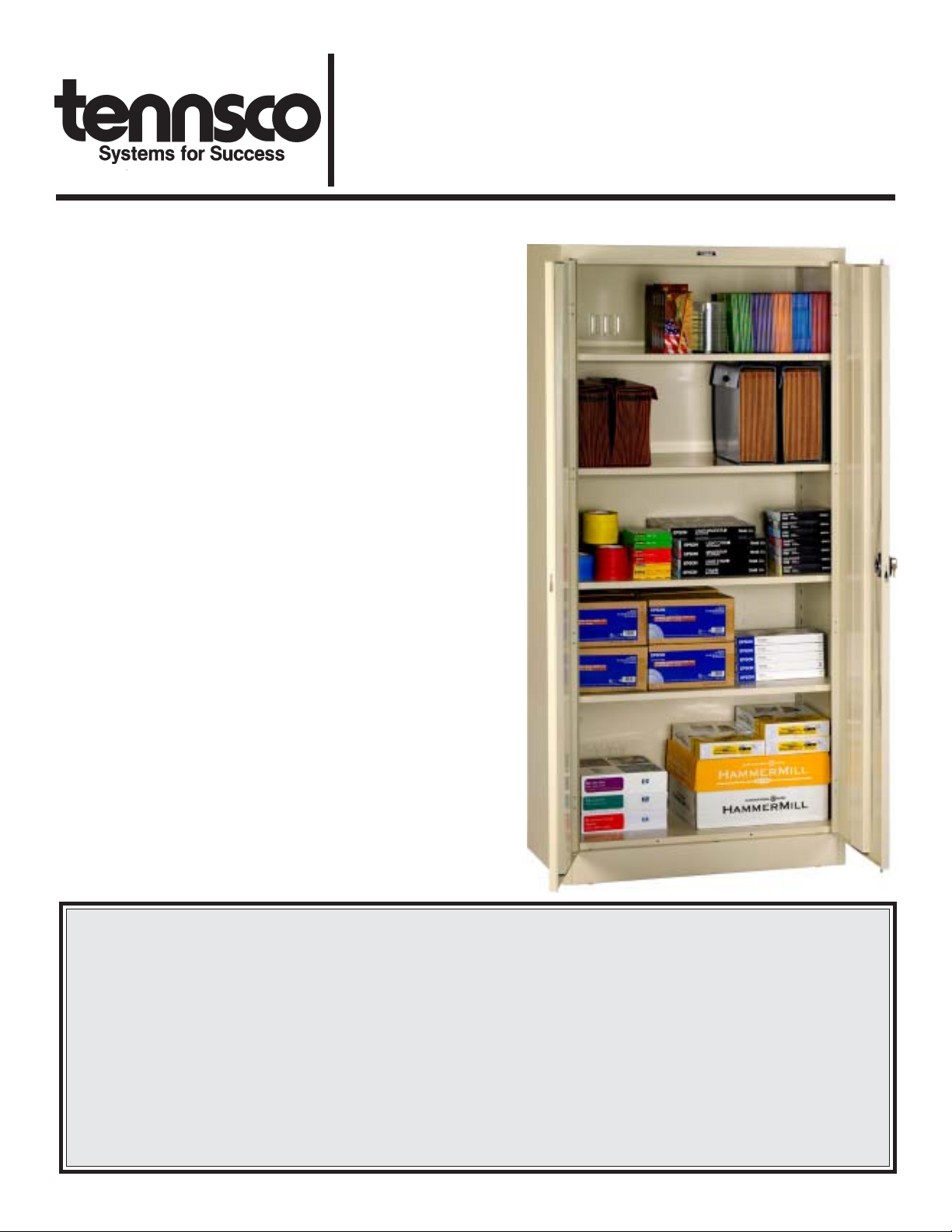
Congratulations on your purchase of a Tennsco
Deluxe Storage Cabinet! Tennsco's 1870RH and
2470RH units are general purpose storage cabinets
that provide a level of quality you won't find elsewhere.
They provide secure storage for office supplies, books,
records, small parts, tools, etc.
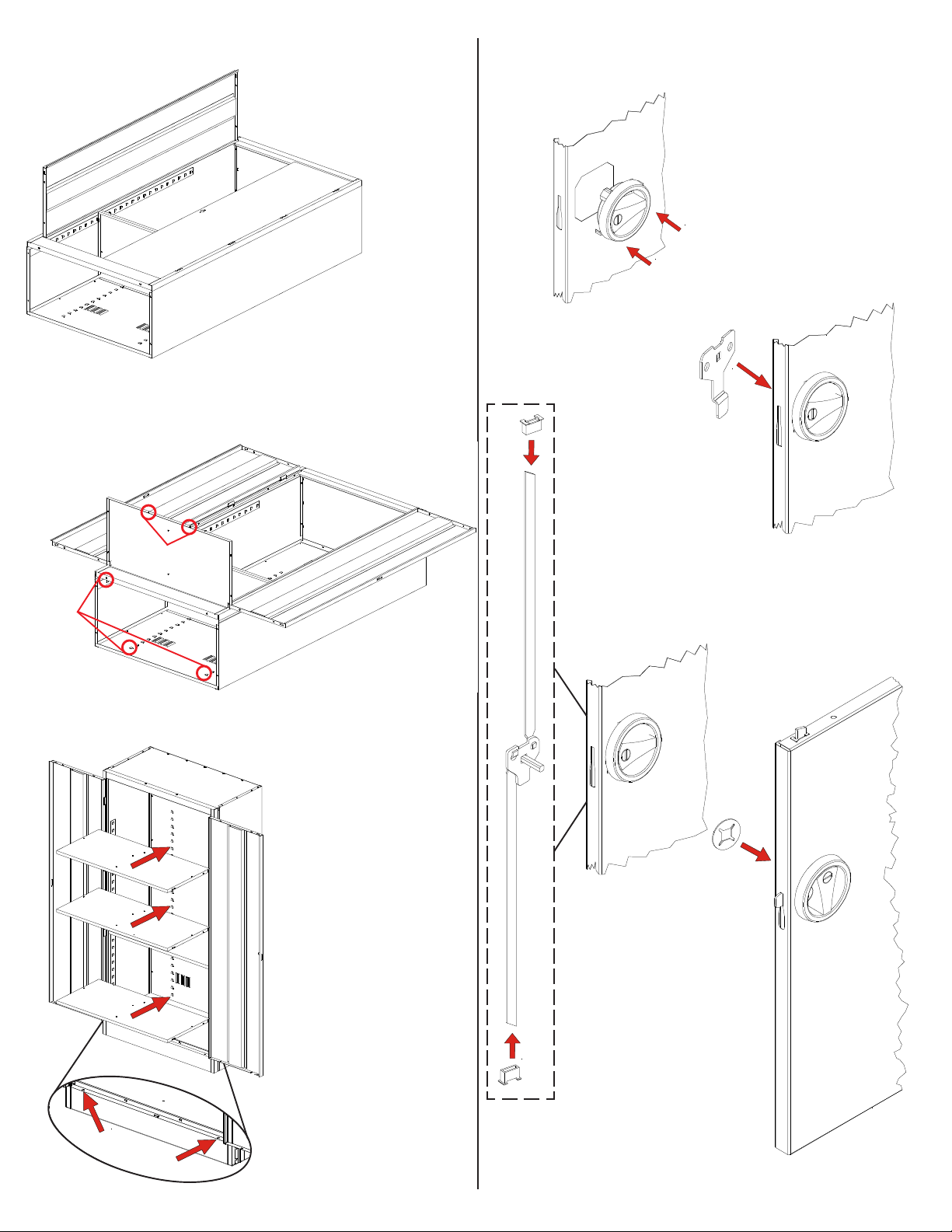
These cabinets offer five openings with four adjustable
shelves, two brushed chrome handles (one fixed and
one lockable with two keys), and a three-point locking
system for extra security. Additional features include
rear louvres for ventilation and nylon lock-bar guides
to ensure quiet operation.
Tennsco's cabinets are constructed from top quality 22
to 24 gauge steel with a 16 gauge frame, and offers
weight capacities of up to 200 lbs. per shelf (evenly
distributed). Our attractive and durable powder-coated
paint finish will provide for years of service.
GENERAL SAFETY INFORMATION
Some parts may have sharp edges. CARE must be taken
when handling various pieces to avoid injury. For safety,
wear a pair of work gloves when assembling or performing
any maintenance on your cabinet.
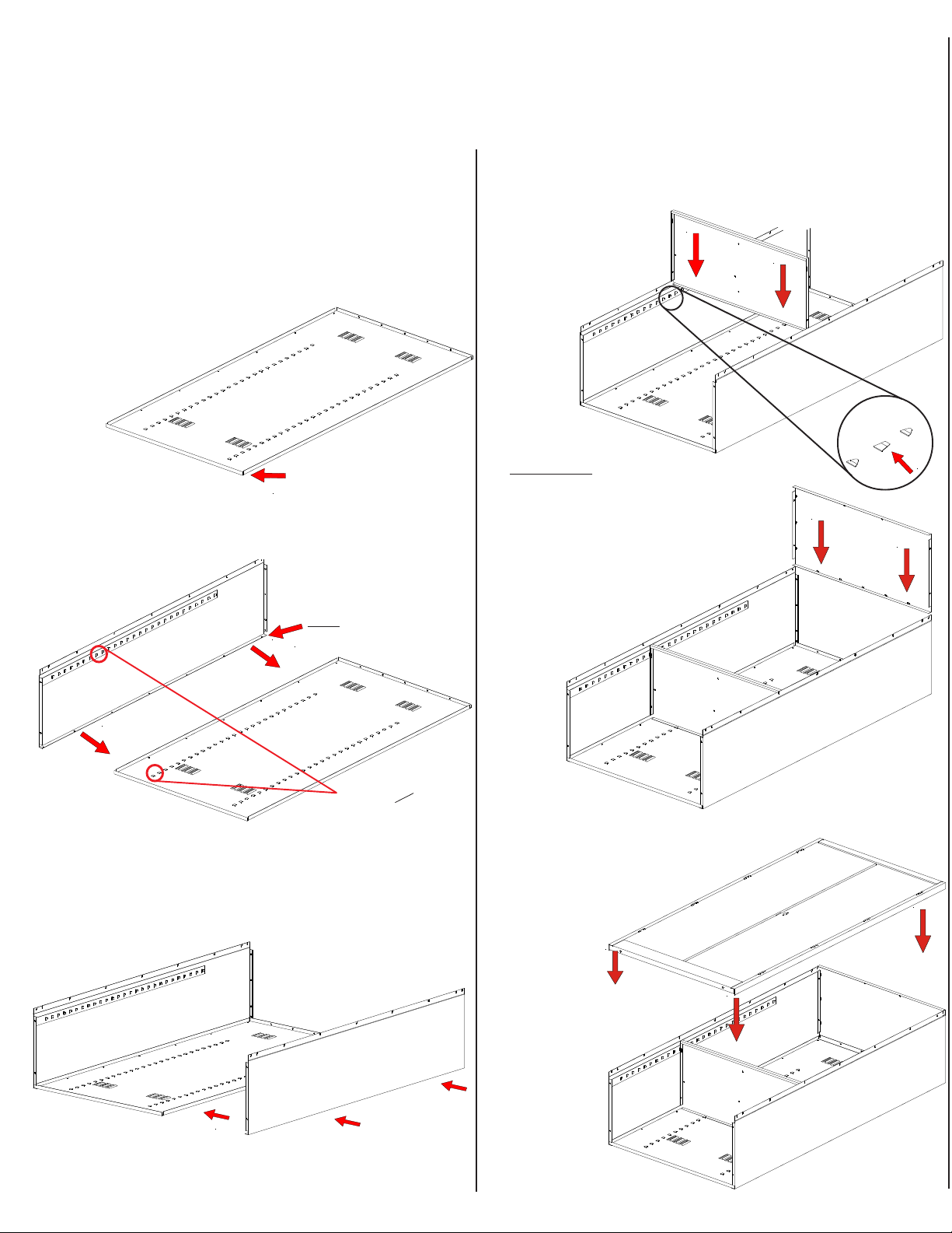
ASSEMBLY INSTRUCTIONS & PARTS MANUAL #1840409
Tennsco Corp., Dickson, TN 37056-1888 • (615) 446-8000
TENNSCO DELUXE STORAGE CABINET
Models 1870RH and 2470RH
LIMITED WARRANTY
Tennsco warrants goods purchased hereunder to be free of defects in materials and workmanship for a period of one (1) year from the date of shipment, hereunder.
This warranty shall not apply in the event goods are damaged as a result of misuse, abuse, neglect, accident, improper application, modification or repair by persons
not authorized by Seller, where goods are damaged during shipment, or where the date stamps on the goods have been defaced, modified or removed. UNLESS
CONSIDERED UNENFORCEABLE OR UNLAWFUL UNDER APPLICABLE LAW:
a. ALL IMPLIED WARRANTIES, INCLUDING BUT NOT LIMITED TO WARRANTIES OR MERCHANTABILITY AND FITNESS FOR A PARTICULAR PURPOSE
AREHEREBYEXCLUDED:
b. BUYERS REMEDY, IF ANY, FOR ANY DEFECTIVE GOODS SHALL BE LIMITED TO A REFUND BY SELLER OR REPLACEMENT OF THE GOODS AT
SELLER’S OPTION, AND SHALL IN NO EVENT INCLUDE DAMAGES OF ANY KIND, WHETHER INCIDENTAL, CONSEQUENTIAL OR OTHERWISE.
NO GOODS ACCEPTED FOR RETURN WITHOUT PRIOR APPROVAL. Seller shall have the right to inspect any goods claimed to be defective at Buyers place
of business or require Buyer to return the goods to Seller for inspection on Seller’s premises. Transportation charges covering returned goods will be borne by
Seller only if such goods are proven to be defective, are covered by this warranty and are returned within the warranty period stated above.
TENNSCO Corp., P.O. BOX 1888, DICKSON, TN 37056-1888
(615) 446-8000 or (866) 446-8686 (toll free)

Tools needed: An 11/32" nut driver (provided free with unit); a hammer; and a flathead screwdriver.
Two people recommended for installation. Approximate assembly time: 15 to 25 minutes.
INSTALLATION OF 1870RH AND 2470RH CABINETS
1. The reference numbers used throughout this
sheet refer to the illustration on the back cover.
This is to help you to identify the various parts as
they are mentioned.
2. Place the cabinet back (Ref. No. 1) on a
protected surface to prevent
scratching the paint.
The flanges should
be facing
upward.
4. Attach the right side (Ref. No. 3) to the back in
the same manner
as you did in step 3,
again making sure that
the flange is around
the back and
that the lances on the shelf adjustment strips are
pointed in the same
direction as those on the
back and left side.
Flanges face upward
3. Attach the left side (Ref. No. 2) to the back by
placing flange (A) around the back and
bolting the back
and side
together
with seven bolts
and nuts (Ref. Nos. 14 &15). Be sure that the
lances on all shelf adjustment strips (B) point in
the same direction.
Flange goes
under back
B
A
All lances point
UP on both
back and side.
5. To help hold the sides in position, insert one
shelf (Ref. No. 4) into the approximate center of
the unit, inserting the shelf edges into the
lances on all four shelf adjustment strips.
Be sure that the
channeled edge of
the shelf is toward
the cabinet
front. If
a lance
is too
tight, it
may be
helpful to use
a screwdriver to
SLIGHTLY pry it open.
6. Place the top (Ref. No. 5) onto
the unit. Be sure that the flanges
tuck inside the cabinet sides and
back. Secure with 11 bolts and
nuts (three along each side,
and five in the back).
The front of the
top will bolt
into place
in step
8.
7. With both doors in the closed position, lift the door
and frame assembly (Ref. No. 6)
and place it over the cabinet
body. Be aware that the
door latches have
not yet been
attached, so
the doors
could potentially swing
open if the door frame is
held in an upside-
down position.
The door
frame should
cover
the
outside edges
of the entire
storage cabinet front.
Inset A

2. Turn the handle to the
open position, and place
the locking cam (Ref.
No. 10) over the square shank of the door
handle. The latch must be
facing downward as
shown at right.
10. Insert the remaining
shelves at your desired
levels. The shelf you
inserted earlier may
also be moved to a
different level if
desired.
1. Place the locking handle (Ref. No. 9) through
the hole in the right hand
door and push until it
snaps into place.
Handle/LockingSystemInstallationInstructions
B
B
8.
With the door & frame assembly in place, attach it
securely to the unit by opening each door,
one at a time, and securing
the frame assembly using
2 bolts and 20
nuts
(Ref. Nos. 14
and 15). This
will require
attaching
nuts to the
nine pre-welded
bolts along each
side,
plus two bolts and
nuts along the top. The bottom
will attach to the frame in Step 9.
11. The cabinet must be
level in order for the
doors to close
properly. Levelers
may be adjusted by
placing a screwdriver
through the hole in
each end of the sill
and adjusting the
leveling screw.
Leveler
Access Holes
A
4. Place the lock-
ing cam retainer (Ref.
No. 12) over the
square shank of the
door handle. Tap on
the edges of the cam
retainer with a hammer
until retainer sits firmly
against the locking
cam.
9. Place the bottom (Ref. No. 7) in the lowest notch
of the shelf adjusting strips on the sides and
back. Make sure the flange with two holes faces
the front, and that it is over the flange of
the frame sill. If
necessary,
you may
push out on
the side walls to
enable the bottom to
more easily slide into position. Attach the shelf
securely by bolting the bottom to the frame sill
with two bolts and nuts.
Two holes
must be in front.
Insert shelf into
bottom lances.
3. With the handle still
in the open position,
hook the locking bars (Ref. No. 8) to
the locking cam (see "A" at left). Then,
hold the lock bars in position while
sliding the nylon lock bar guide
inserts (Ref. No. 11) over the lock bar
ends and through the
door slots (see "B" at
left).

REPLACEMENT PARTS
We make every effort to ensure that all units ship complete with all parts and arrive undamaged. However,
should your unit contain missing or damaged parts, replacements may be obtained directly from us. To obtain
proper replacement parts, follow the instructions below:
TO OBTAIN PROPER REPLACEMENT PARTS, PLEASE PROVIDE THE FOLLOWING INFORMATION:
(This information may be sent to us online using the form at www.tennsco.com/replacement.cfm)
lModel Number (1870RH or 2470RH) lPurchase Date
lDescription of part(s) needed and part lYour company name
number(s) as shown in Parts List (above) lContact person's name
lColor (i.e. Medium Grey, etc.) lWho the product was purchased from
lWas item missing, or was it damaged? lYour shipping address
Tennsco Corp., P.O. Box 1888, Dickson, TN 37056-1888 Customer Service: (866) 446-8686 Fax: (866) 445-7260
If requesting parts by telephone, ask for customer service and have as much of the above information ready as possible.
Cam Retainer
(Ref. No. 12)
Right Side
(Ref. No. 3)
Dummy
Handle
(Ref. No.
13)
Back Panel
(Ref. No. 1)
Locking Cam
(Ref. No. 10)
Locking Handle
with Keys
(Ref. No. 9)
REF. NO. PART NO.
DESCRIPTION
1 Back panel 1 043BA 1 043BA
2 Left side 1 043LS 1 044LS
3 Right side 1 043RS 1 044RS
4 Shelf 4 301 4 302
5 Top 1 043TO 1 044TO
6 Door & Frame Assembly 1 043DF 1 043DF
7 Bottom 1 043BO 1 044BO
8 Locking bar set 1 043LB 1 043LB
9 Locking handle w/keys & hardware 1 RH-1 1 RH-1
10 Locking cam* 1 944LC 1 944LC
11 Locking bar guide insert (nylon)* 2 944GI 2 944GI
12 Cam retainer* 1 944CR 1 944CR
13 Tennsco nut driver 1 TOOL-2 1 TOOL-2
14 #8-32 x 3/8"bolts* (not shown above) 31 * * 31 * *
15 #8-32 nuts* (not shown above) 47 * * 47 * *
*Included in Ref. No. 9, locking handle with keys and hardware (Part No. RH-1). **Available Locally
QTY.
Shelf
(Ref.
No. 4)
Door & Frame
Assembly
(Ref. No. 6)
Left Side
(Ref. No. 2)
Top
(Ref. No. 5)
Locking Bar Guide
Nylon Insert
(Ref. No. 11)
Locking Bar Set
(Ref. No. 8)
Tennsco Nut Driver
(Ref. No. 13)
1870RH (18"d cabinet) 2470RH (24"d cabinet)
QTY. PART NO.
Bottom
(Ref.
No. 7)
This manual suits for next models
1
Other Tennsco Storage manuals
Popular Storage manuals by other brands

Atlas Copco
Atlas Copco ZenergiZe ZBP15 Instruction book

FEB
FEB HV5120-S Series product manual

Closet Maid
Closet Maid 2-Door Versa Cabinet 12075 Assembly instructions

Tripp Lite
Tripp Lite U2BLOCK-A-KEY quick start guide

Promise
Promise Pegasus M4 product manual

Checkpoint
Checkpoint 13000 Series Installation