Tennsmith U48-22 Guide

OPERATION, PARTS & MAINTENANCE MANUAL
MODELS U48-22 S48-22
Model: Purchased From:
Serial #: Date Received:
6926 Smithville Hwy., McMinnville, TN 37110
931-934-2211 / Fax: 931-934-2220
www.tennsmith.com
ShopRPMachinne

Tennsmith Inc. / 6926 Smithville Hwy. / McMinnville, TN 37110 / 931-934-2211 / Fax 931-934-2220
www.tennsmith.com
2
ShopRPMachinne

Tennsmith Inc. / 6926 Smithville Hwy. / McMinnville, TN 37110 / 931-934-2211 / Fax 931-934-2220
www.tennsmith.com
3
FOREWORD
This manual has been prepared for the owner and operators of Tennsmith U48-22 and S48-22 model bench
brakes. Its purpose, aside from operations instructions, is to promote safety through the use of accepted
operating procedures. Read all instructions thoroughly before operating the brake.
Also contained in this manual is the parts list for your brake. It is recommended that only Tennsmith or factory
authorized parts be used as replacements.
WARRANTY
Your brake has a three year limited warranty from the date of purchase. The terms of the warranty are stated
on the warranty registration card shipped with your machine. Please complete and return this card to activate
your warranty.
SAFETY INSTRUCTIONS
1. Know the safety and operating instructions contained in this brochure. Become familiar with and
understand the limitations of this machine. Always practice safety.
2. Wear approved eye safety protection such as glasses, goggles, etc., when operating the brake
to protect your eyes.
3. Wear protective foot wear or safety shoes.
4. Keep your hands clear of the nose bar and clamping area of the brake. Keep hands clear of the
apron area of the brake when making bends.
5. When bending capacity material use your legs and arms for making the bend, similar to lifting a
heavy object, to avoid back strain. Maximum length and capacity material is a two person job.
Adjust the counterweights to provide maximum assistance on heavy bends.
6. Never use a pipe or bar on the clamp handles or apron handles for additional leverage.
7. Keep clear of the apron swing area while operating the brake.
8. Keep the work area around the brake clear and clean to avoid slipping or tripping.
SAFETY LABEL
ShopRPMachinne

Tennsmith Inc. / 6926 Smithville Hwy. / McMinnville, TN 37110 / 931-934-2211 / Fax 931-934-2220
www.tennsmith.com
4
RECEIVING THE BRAKE
Upon receipt, closely examine the brake for damage during shipment. Report to your distributor any damage
that may have occurred during transit.
USE CAUTION IN HANDLING AND MOVING THIS BRAKE. Please note that brake is top heavy. Lift the
brake only from the ends as it is top heavy. Approximate weights for the respective models are as follows:
U48-22 280lbs / 127kg S48-22 220lbs / 100kg
INSTALLING THE BRAKE
Locate the brake in a well lighted area on a solid workbench capable of supporting the weight of the machine.
The bench should be generally be secured to the floor by bolts or lags screws. Be certain that you have
adequate clearance to swing the apron and that the brake is at a comfortable and convenient working height.
The brake should be removed for the skid. Use lag screws or bolts with expandable shields or similar holding
devices through mounting feet on the bottom of the lag assemblies to bolt the brake to the bench. The brake
must be fastened to the bench for safe operation.
THE BRAKE WILL NOT BEND PROPERLY IF IT IS NOT LEVEL.
ShopRPMachinne

Tennsmith Inc. / 6926 Smithville Hwy. / McMinnville, TN 37110 / 931-934-2211 / Fax 931-934-2220
www.tennsmith.com
5
OPERATING THE BRAKE
CAPACITY: The capacity of the brake is 22 gauge mild steel or 26 gauge stainless.
BENDING: This function is accomplished by clamping the work piece under the hold down assembly (3, 4) so
that the line of the bend is held at the forward edge of the nose bar or fingers and by elevating the apron
assembly (2) until the desired degree of bend is obtained. The maximum degree of bend is approximately 130
degrees. Due to the “spring back” in various materials some over bending maybe required to get the desired
bend angle.
ADJUSTING FOR METAL THICKNESS: The hold down assembly (3, 4) must be adjusted to allow for
clearance of the bend material according to the thickness of the material being worked. This adjustment is
made by slightly releasing the clamping pressure and moving the forward edge of the nose bar or fingers back,
away from the edge of the clamp block on the base. This adjustment is made by loosening the set screw
(52) for the eccentric pin (51) one on each end of the hold down assembly and turning the eccentric pin
to move the edge of the hold down toward or away from the edge of the clamp block. For 22 gauge and
lighter material allow a clearance equal to 1.5 to 2 times the thickness of the material. A larger bend radius can
be accomplished by increasing the clearance.
ADJUSTING THE CLAMPING PRESURE: The clamping pressure should be adjusted according to the
thickness of the material being worked. A common cause of forming problems is the result of either
inadequate or excessive clamping pressure. Too much clamping pressure on one or both handles typically
will result in over bending the material on that particular end or relative to the center portion of the brake. Not
enough clamping pressure force will allow the material to slip during the bending process and result in an
under bent section. This under bending is often encountered in the center of the brake.
Clamping pressure should be enough to hold the material securely in place but not so great as to require
undue effort in locking the clamp handles. Clamping pressure on the ends of the brake is adjusted by turning
the nuts (54) on the threaded rod portion of the yoke assembly (47) which is below the clamp swivel (55). The
lift of the hold down assembly is adjusted by turning the nut above the clamp swivel. When the clamping
pressure is properly adjusted, lock the nuts against the clamp swivel to prevent any change in adjustment.
ShopRPMachinne

Tennsmith Inc. / 6926 Smithville Hwy. / McMinnville, TN 37110 / 931-934-2211 / Fax 931-934-2220
www.tennsmith.com
6
HEMMING:
Note: Forming hems is a secondary operation for a hand brake. If you adjust the brake to close a hem in
the center of the work piece, the brake most likely will not bend straight. A hem is formed by making an acute
(reverse) bend in the work piece and then clamping the bent flange in the hold down (1) to press the flange
closed (to 180 degrees). Often the hem will not fully close in the center of a long work piece due to fact that the
outer ends of the brake are more rigid than the center. Here it is especially important that the brake is
sufficiently crowned and that there is proper clamping pressure at the center of the brake. Also the situation
can be improved by inserting a strip of material (of the same thickness as the work piece) between the work
piece and the clamp block slightly longer than the open portion of the hem. Re-clamp the hold down to close
the hem. A tinner’s mallet or hammer is also useful for closing hems. Be cautious not to use excessive force on
the clamp handles to close the hem.
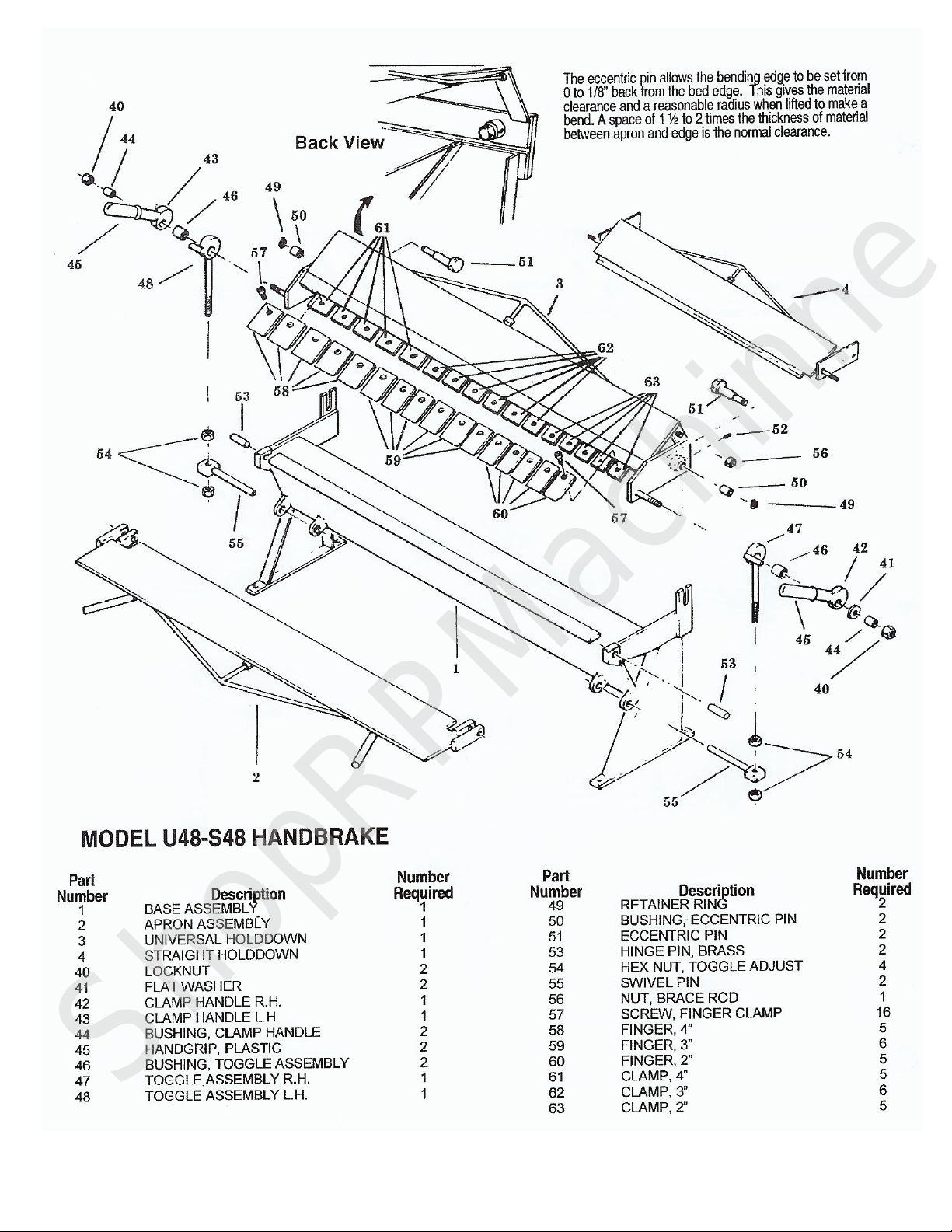
OVERBENDING: The hold down assembly should be moved back on the end where the over bending occurs
by slightly unclamping the clamp handles, loosening the set screw and turning the eccentric pin. When the
correction is made retighten the set screw.
U48-22 BOX AND PAN BENDING: The fingers can be removed and repositioned on the hold down
assembly by moving the clamp handle fully to the rear and loosening the finger clamp screws. Reposition the
fingers to assemble the desired width and secure the fingers to the hold down by tightening the finger clamp
screws. Be certain that the tops of the fingers are flush and parallel with the milled edge on the hold down and
the finger clamps are parallel with the bottom edge of the hold down. As a general rule, use the wider finger
first and fill in with the narrower fingers. Small gaps between the fingers may be left with no adverse effect to
the work piece. The maximum depth of box or pan which can be bent is 3-Inches.
ADJUSTING THE BRAKE
Your brake when assembled at the factory was adjusted for proper operation. Due to handling and
repositioning, the brake my require adjustment and alignment. Read the adjustment and operating instructions
completely before making any adjustments. Operate the brake and bend some material first before attempting
any major adjustments.
BASIC ALIGNMENT: The clamp block on the base of the brake should be straight. This is the reference
point for all of the other alignment operations in adjusting the brake. Raise or lower the center of the brake by
adjusting the center of the brake by adjusting the center truss rod. NOTE: The U48 has four truss rods that
serve as the adjustments of the primary components. The S48 is equipped with three truss rods which facilitate
adjustment of the brake’s three primary weldments. Adjustments are accomplished through rotation of the nut
located on the studs mounted perpendicular to the weldments. The U48 comes with an additional brace which
serves to correct the alignment of the center fingers of the brake with respect to the ends. This adjustment is
made by turning the nut located on the right hand side of the hold down assembly.
ShopRPMachinne

Tennsmith Inc. / 6926 Smithville Hwy. / McMinnville, TN 37110 / 931-934-2211 / Fax 931-934-2220
www.tennsmith.com
7
HOLD DOWN ALIGNMENT: The forward edge of the fingers / nose bar on the hold down assembly should
be even and parallel to the edge of the clamp block on the base. Release any clamping pressure on the hold
down assembly by pushing the clamp handles slightly to the rear. Loosen the set screw located on each end of
the hold down assembly and turn the eccentric to move the forward edge of the clamp block. Check to see that
the edge of the hold down is flush with the edge of the block throughout the entire length of the brake. The
central portion of the hold down assembly can be adjusted forward / backward and up or down via truss rod
adjustment.
PRECAUTIONS
DO NOT USE THE BRAKE TO BEND RODS, NAILS OR WIRE. THIS WILL CAUSE DAMAGE TO THE
EDGE OF THE NOSE BAR AND APRON.
ALWAYS ADJUST THE CLEARANCE AND CLAMPING PRESSURE FOR DIFFERENT THICKNESSES OF
MATERIAL.
DO NOT EXCEED THE CAPACITY OF THE BRAKE. MAKE CERTAIN THAT APRON SUPPORT ANGLE
AND APRON INSERT IS ATTACHED TO THE APRON ASSEMBLY WHEN MAKING CAPACITY BENDS.
OTHERWISE PERMANENT DAMAGE TO THE APRON MAY RESULT.
DO NOT bend seams, hems of locks unless the material is notched or the clearance is adjusted to double the
seam/hem thickness. The capacity of this brake is 22 gauge (0.030). Multiple layers of material which exceed
this dimension are beyond the capacity of the brake.
DO NOT USE PIPE EXTENSIONS TO GAIN ADDITIONAL LEVERAGE ON THE CLAMP HANDLES.
ALWAYS USE MATERIAL WITH SQUARE SHEARED EDGES FOR BEST RESULTS. ROLLED EDGES,
BENT OR WARPED MATERIAL WILL CUASE THE MATERIAL TO BOW WHEN BENT. KEEP SHEAR
BLADES AND SLITTER KNIVES SHARP.
ALWAYS BEND SHORT PIECES OF MATERIAL IN THE CENTER OF THE BRAKE IN ORDER TO
EQUALIZE THE STRESS.
ORDERING PARTS
If you are ordering parts please furnish both the model and serial number of your machine. Part’s can be
obtained directly from Tennsmith Inc.
ShopRPMachinne

Tennsmith Inc. / 6926 Smithville Hwy. / McMinnville, TN 37110 / 931-934-2211 / Fax 931-934-2220
www.tennsmith.com
8
Bench Model Bending Brakes Specification
Models
U48-22
S48-22
Capacity, mild steel 22ga / 0,75mm 22ga / 0,75mm
Bending length 48-1/4in / 1225mm 48-1/4in / 1225mm
Maximum depth of box 3 in / 76.2 mm N/A
Maximum lift of beam 7/8 in / 22.2mm 7/8 in / 22.2mm
Front to rear adjustment ¼ in / 6mm ¼ in / 6mm
Minimum reverse bend 5/16 in / 7.9mm 5/16 in / 7.9 mm
Minimum flange
in capacity material 3/8 in / 9.5mm 3/8 in / 9.5mm
Dimensions, LxWxH
Weight 280 lbs / 127 kg 220 lbs / 100 kg
ShopRPMachinne
This manual suits for next models
1
Table of contents
Other Tennsmith Tools manuals
Popular Tools manuals by other brands

Central Forge
Central Forge 32114 Assembly & operating instructions

EINHELL
EINHELL DTA 25/1 Operating and maintenance instructions

HSINHO
HSINHO EXP951 Operator's manual

HAUL MASTER
HAUL MASTER 61625 Owner's manual & safety instructions

Yukon
Yukon Gear & Axle quick start guide

Belden
Belden PPC HAPI Miniflex user manual