Tennsmith Inc. / 6926 Smithville Hwy. / McMinnville, TN 37110 / 931-934-2211 / Fax 931-934-2220 3
www.tennsmith.com
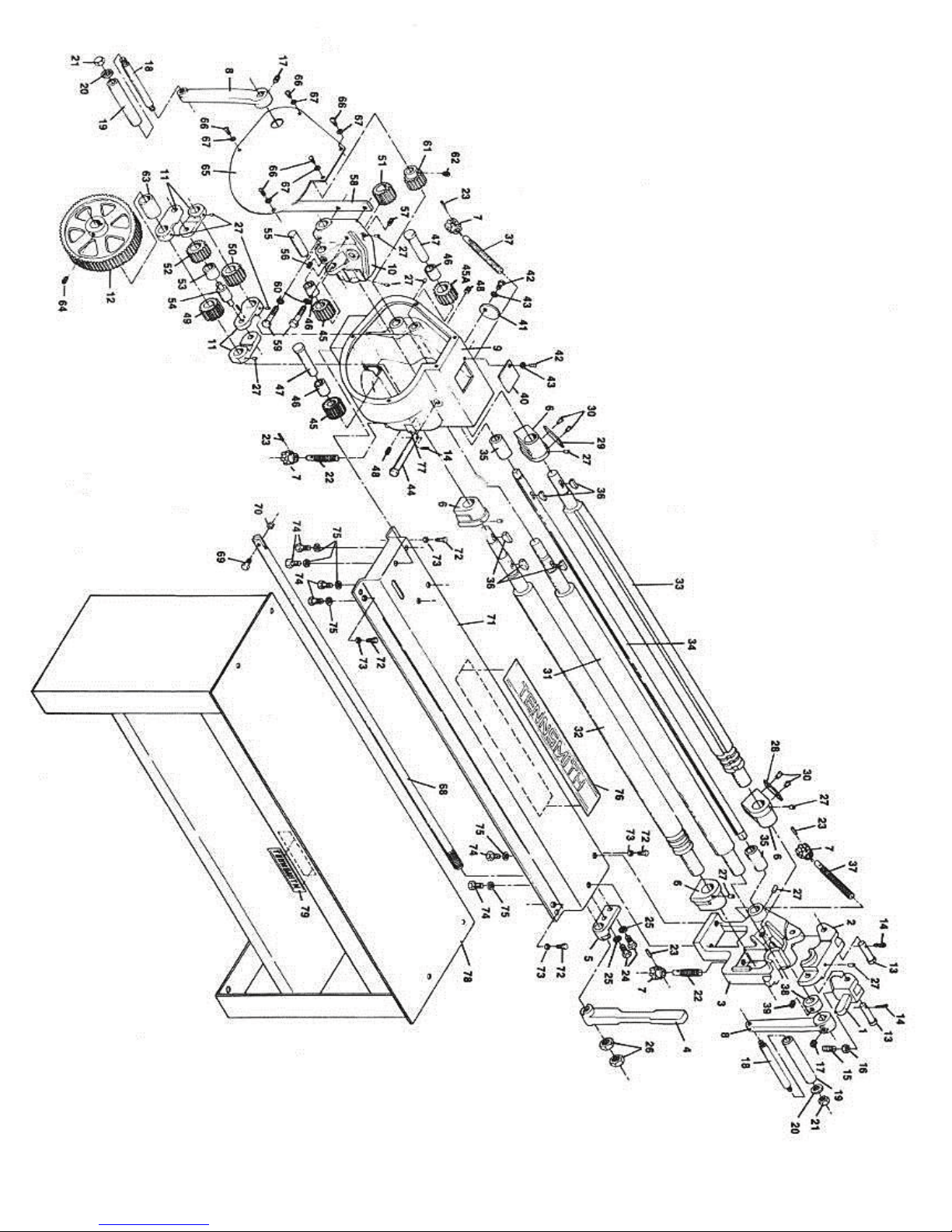
SR48 / Parts List
PART # DESCRIPTION REQ’D # PART # DESCRIPTION REQ’D #
SR48-401 LOCK, TOP LATCH 1 SR48-441 COVER PLATE, TOP R.H. HOUSING 1
SR48-402 TOP LATCH 1 SR48-442 SCREW, COVER PLATE 2
SR48-403 RIGHT HAND SIDE FRAME 1 SR48-443 WASHER, SCREW LOCK 2
SR48-404 LIFT HANDLE 1 SR48-444 PIN, SWIVEL BLOCK 1
SR48-405 LIFT CAM 1 SR48-445 IDLER GEAR-16T 3
SR48-406 BLOCK, ROLL ADJ. 4 SR48-445A IDLER GEAR-18T 1
SR48-407 HANDKNOB, ROLL ADJ. 4 SR48-446 BUSHING, IDLER GEAR 3
SR48-408 HANDCRANK 2 SR48-447 PIN, IDLER GEAR 2
SR48-409 LEFT HAND HOUSING 1 SR48-448 SET SCREW, IDLER PIN 2
SR48-410 BLOCK, TOP ROLL SWIVEL 1 SR48-449 GEAR, LOWER FRONT ROLL 1
SR48-411 LINKS 4 SR48-450 GEAR, BACK ROLL 1
SR48-412 12” GEAR 1 SR48-451 GEAR, TOP ROLL 1
SR48-413 CLEVIS PIN, TOP LATCH 2 SR48-452 GEAR, LOWER IDLER 1
SR48-414 COTTER PIN 3 SR48-453 BUSHING, LOWER IDLER GEAR 1
SR48-415 SET SCREW, LOCK 1 SR48-454 SPACER PIN, GEAR 1
SR48-416 NUT, SET SCREW LOCK 1 SR48-455 PIN, SWIVEL BLOCK IDLER 1
SR48-417 SET SCREW, HANDCRANK 2 SR48-456 SET SCREW, PIN 1
SR48-418 SHAFT, HANDCRANK 2 SR48-457 SCREW, SWIVEL BLOCK 1
SR48-419 HANDLE, HANDCRANK 2 SR48-458 LEVER, LIFTING 1
SR-48-420 WASHER, HANDLE 2 SR48-459 SCREW, LIFTING LEVER 2
SR48-421 NUT, HANDLE LOCK 2 SR48-460 WASHER, SCREW LOCK 2
SR48-422 SCREW, LOWER ROLL ADJ. 2 SR48-461 GEAR, CRANK SHAFT 1
SR48-423 SPLIT PIN, ROLL ADJ. HANDKNOB 4 SR48-462 SET SCREW, GEAR 1
SR48-424 SCREW, LIFT CAM 2 SR48-463 SPACER 1
SR48-425 WASHER, LIFT CAM SCREW LOCK 2 SR48-464 SET SCREW, 12” GEAR 1
SR48-426 NUT, LIFT HANDLE LOCK 2 SR48-465 COVER 1
SR48-427 GREASE FITTING 13 SR48-466 SCREW, COVER 5
SR48-428 SCALE, RIGHT HAND 1 SR48-467 WASHER, SCREW LOCK 5
SR48-429 SCALE, LEFT HAND 1 SR48-468 ROD, LIFTING 1
SR48-430 DRIVE SCREW, SCALE 4 SR48-469 SCREW, LIFTING ROD 1
SR48-431 ROLL, TOP 1 SR48-470 NUT, SCREW LOCK 1
SR48-432 ROLL, LOWER FRONT 1 SR48-471 BASE 1
SR48-433 ROLL, BACK 1 SR48-472 SCREW, BASE LEVELING 4
SR48-434 SHAFT, CRANK 1 SR48-473 NUT, SCREW LOCK 4
SR48-435 BUSHING, CRANK SHAFT 2 SR48-474 SCREW, MOUNTING 6
SR48-436 WOODRUFF KEY 5 SR48-475 WASHER, SCREW LOCK 6
SR48-437 SCREW, BACK ROLL ADJ. 2 SR48-476 DECAL, BASE 1
SR48-438 COLLAR, CRANK SHAFT RETAINING 1 SR48-477 SERIAL PLATE 1
SR48-439 SET SCREW, COLLAR 1 SR48-478 STAND, OPTIONAL 1
SR48-440 COVER PLATE, TOP L.H. HOUSING 1 SR48-479 DECAL, STAND 1