TENS Pros EMS 5.0 User manual


TENSPros
1
INDEX
Chapter Contents Page
Index ..................................................................... 1
1. Introduction .......................................................... 2
2. Cautions ................................................................ 3
3. Warnings............................................................... 4
4. Contraindication .................................................. 4
5. Adverse Reactions ............................................ 5
6. General Description ........................................... 5
7. Construction ......................................................... 5
8. Technical Specifications .................................. 6
9. ReplaceableParts ............................................. 7
10. Accessories .......................................................... 7
11. Graphic Symbols................................................. 8
12. Attachment of ElectrodesLead Wires ............ 8
13. LeadWireMaintenance ..................................... 9
14. ElectrodeOptions .............................................. 9
15. ElectrodePlacement ......................................... 9
16. Tips ForSkin Care .............................................. 10
17. Applicationof Re-usable Self Adhesive
Electrodes ............................................................ 11
18. Adjusting the Controls ........................................ 12
19. BatteryInformation ............................................ 15
20. Maintenance, Transportation and Storage .....17
21. SafetyControl ..................................................... 18
22. Malfunctions......................................................... 18
23. ConformitytoSafetyStandards ....................... 19
24. Warranty .............................................................. 19
PDF created with FinePrint pdfFactorytrial version http://www.pdffactory.com

TENSPros
32
Then when the pulse ceases, the muscle relaxes and the cycle
starts over again,(Stimulation, Contraction and Relaxation.) Powered
muscle stimulators should only be used under medical supervision
for adjunctive therapy for the treatment of medical diseases and
conditions.
Chapter 2 : CAUTIONS
1. Safety of powered muscle stimulators for use during pregnancy
has not been established.
2. Caution should be used for patients with suspected or diagnosed
heart problems.
3. Caution should be used for patients with suspected or diagnosed
epilepsy.
4. Caution should be used in the presence of the following:
a. When there is a tendencyto hemorrhage followingacute trauma
or fracture;
b. Following recent surgical procedures when muscle contraction
may dis rupt the healing process;
c. Over the menstruating or pregnant uterus; and
d. Over areas of the skin which lack normal sensation.
5. Some patients may experience skin irritation or hypersensitivity
due to the electrical stimulation or electrical conductive medium.
The irritation can usually be reduced by using an alternate
conductive medium, or alternate electrode placement.
6. Electrode placement and stimulation settings should be based on
the guidance of the prescribing practitioner.
7. Powered muscle stimulators should be kept out of the reach of
children.
8. Powered muscle stimulators should be used only with the leads
and elec trodes recommended for use by the manufacturer.
Chapter 1 : INTRODUCTION
EXPLANATION OF EMS
Electrical MuscleStimulation is an internationallyaccepted andproven
way of treating muscular injuries. It works by sending electronic
pulses to the muscle needing treatment; this causes the muscle to
exercise passively.
It is a product derived from the square waveform, originally invented
by John Faraday in 1831. Through the square wave pattern it is able
to work directly on muscle motor neurons. EMS has low frequency
and this in conjunction with the square wave pattern allows direct
work on muscle groupings. This is being widely used in hospitals
and sports clinics for the treatment of muscular injuries and for the
re-education of paralyzed muscles, to prevent atrophy in affected
muscles and improving muscle tone and blood circulation.
HOW EMS WORKS
1. Relaxation of muscle spasms
2. Prevention or retardation of disuse atrophy
3. Increasing local blood circulation
4. Muscle re-education
5. Immediate post-surgical stimulation of calf muscles to prevent
venous thrombosis
6. Maintaining or increasing range of motion
The EMS units send comfortable impulses through the skin that
stimulate the nerves in thetreatment area. When themuscle receives
this signal it contracts as if the brain has sent the signal itself. As the
signal strength increases, the muscle flexes as in physical exercise.
PDF created with FinePrint pdfFactorytrial version http://www.pdffactory.com
TENSPros
54
Chapter 5: ADVERSE REACTIONS
Skin irritation and burns beneath the electrodes have been reported
with the use of powered muscle stimulators.
Chapter 6 : GENERAL DESCRIPTION
The EMS 5.0 is a battery operated pulse generator that sends
electrical impulses through electrodes to the body and reaches the
underlying nerves or muscle group. The device is provided with two
controllable output channels, each independent of each other. An
electrode pair can be connected to each output channel.
The electronics of the EMS 5.0 create electrical impulses whose
Intensity, Pulse Width, Pulse Rate, Contraction, Relaxation and Ramp
may be altered with the switches. Dial controls are very easy to use
and the slide cover prevents accidental changes in the setting.
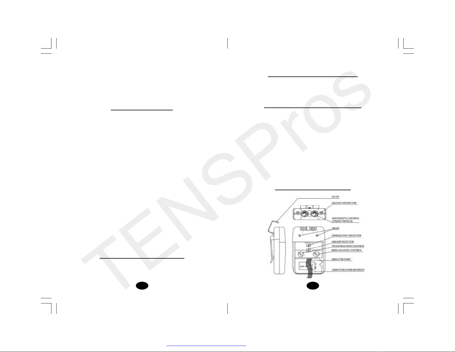
Chapter 7 : CONSTRUCTION
9. Portable powered muscle stimulators should not be used while
driving, operating machinery, or during any activity in which
involuntary muscle con tractions may put the user at undue risk
of injury.
Chapter 3 : WARNINGS
1. The long-term effects of chronic electrical stimulation are
unknown.
2. Stimulation should not be applied over the carotid sinus nerves,
particuarly In patients with a known sensitivity to the carotid
sinus reflex.
3. Stimulation should not be applied over the neck or mouth. Severe
spasm of the laryngeal and pharyngeal muscles may occur and
the contractions may be strong enough to close the airway or
cause difficulty in breathing.
4. Stimulation should not be applied transthoracically in that the
introduction of electrical current into the heart may cause cardiac
arrhythmias.
5. Stimulation should not be applied transcerebrally.
6. Stimulation should notbeapplied overswollen, infected, or inflamed
areas or skin eruptions, e.g., phlebitis, thrombophlebitis, varicose
veins, etc.
7. Stimulation should not be applied over, or in proximity to, cancerous
lesions.
Chapter 4: CONTRAINDICATION
Powered muscle stimulators should not be used on patients with
cardiac demand pacemakers.
PDF created with FinePrint pdfFactorytrial version http://www.pdffactory.com

TENSPros
76
Chapter 9 : REPLACABLE PARTS
The replaceable parts and accessories of EMS devices are as given
below Except leads, electrodes and battery, battery cover, please
do not try to replace the other parts of a device.
PARTS
01 ELECTRODESLEADS
02 ELECTRODES
03 BATTERY 006P 9V
04 BELTCLIP
05 BATTERYCASECOVER
06 LEADCONNECTOR
07 MAINPCB
08 INTENSITY KNOB
09 CONTRACTION KNOB
10 RELAXATIONKNOB
12 PULSERATEKNOB
13 RAMPKNOB
Chapter 10 : ACCESSORIES
Each set N605 EMS are completed with standard accessories as
given below
REF.NO. PRODUCT Q’TY
1. KS4040 40 X 40 MM Adhesive Electrodes 4 pieces
2. KE-24 Electrodes Leads 2 pieces
3. GC-01 9 V Battery, type 6F22 1 piece
4. Instruction Manual 1 piece
5. Carrying Case x 1 EA 1 piece
‘Chapter 8 : TECHNICAL SPECIFICATION
The technical specification details of EMS 5.0 are as follows
MECHANISM TECHICAL DESCRIPTION
01 Channel Dual, isolated between channels
02 Pulse Amplitude Adjustable, 0-80mA
Max output 80mA(peak to peak) into
500ohm load each channel.
03 Voltage Adjustable, 0-40V
Max output 40V(peak to peak ) into
500 ohm load each channel.
04 Wave Form Asymmetrical Bi-Phasic Square Pulse
05 Power supply One 9 Volt Battery, type 6F22
06 Size 95(H) x 65(W) x 23.5(T) mm
07 Weight 115 grams (battery included)
08 Pulse Rate 5, 30, 100 Hz
09 PulseWidth Fixed at 250uS
10 Contraction Time Adjustable, 1~30 seconds
11 RelaxationTime Adjustable, 1~45 seconds
12 RampTime 1, 3 or 5 seconds
13 Operating Temperature : 0°~40°C
Condition Relative Humidity :
30%~75%Atmosphere Pressure :
700Hpa~1060Hpa14Remark
Theremaybeupto a+/-20%tolerance
of all parameters.
PDF created with FinePrint pdfFactorytrial version http://www.pdffactory.com
TENSPros
98
CAUTION
Do not insert the plug of lead wire into the AC power source.
Chapter 13: LEAD WIRE MAINTENANCE
Clean the wires by wiping with a damp cloth. Coating them lightly
with talcum powder will reduce tangling and prolong life.
Chapter 14 : ELECTRODE OPTIONS
You should use the same size and type of electrodes that was
supplied with your EMS device, unless your clinician instructs you to
use a different electrode. Follow application procedures outlined in
electrode packing, to maintain stimulation and prevent skin irritation.
Usethe legally marketed EMS electrode is recommended. The device
is completed with standard carbon film adhesive electrodes in size
4x4cm.
Chapter 15 : ELECTRODE PLACEMENT
The placement of electrodes can be one of the most important
parameters in achieving success with EMS therapy. Of utmost
importance is the willingness of the clinician to try the various styles
of electrode placement to find which method best fits the needs of
the individual patient.
Every patient responds to electrical stimulation differently and their
needs may vary from the conventional settings suggested here. If
the initial results are not positive, feel free to experiment. Once an
acceptable placement has been achieved, mark down the electrodes
Chapter 11 : GRAPHIC SYMBOLS
1. Note Operating Instructions
2. Degree of Electrical Protection BF
3. Do not insert the plug into AC power supply socket
4. Direct Current (DC power source)
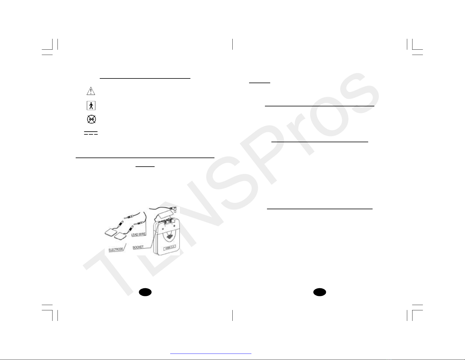
Chapter 12 : ATTACHMENT OF ELECTRODE LEAD
WIRES
The wires provided with the system insert into the jack sockets
located on top of the device. Holding the insulated portion of the
connector, push the plug end of the wire into one of the jacks (see
drawing); one or two sets of wires may be used.
Afterconnecting the wires to the stimulator, attach each wire to an
electrode. Use care when you plug and unplug the wires. Jerking
the wire instead of holding the insulated connector body may cause
wire breakage.
PDF created with FinePrint pdfFactorytrial version http://www.pdffactory.com
TENSPros
1110
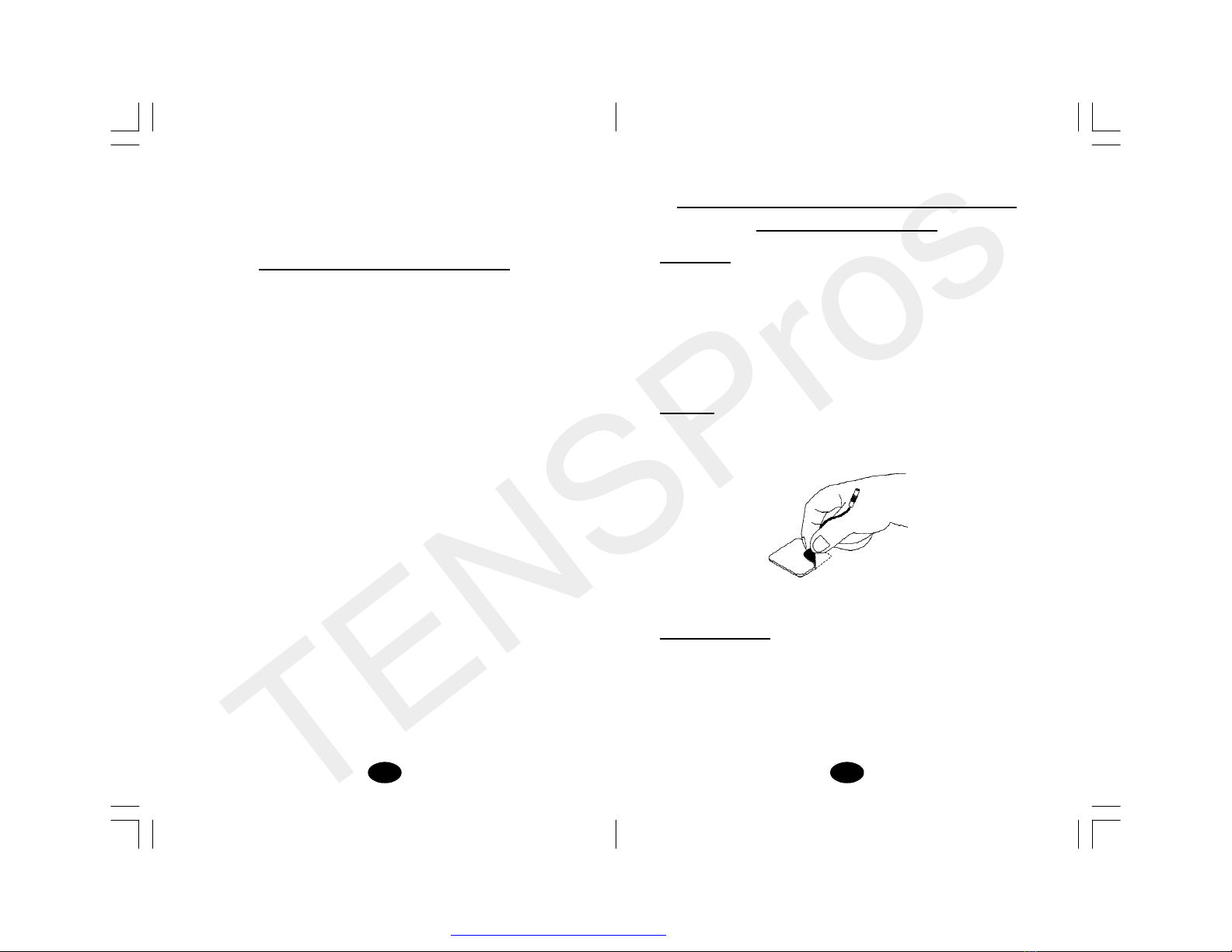
Chapter 17APPLICATION OF RE-USABLE SELF
ADHESIVEELECTRODES
Application
1. Clean and dry the skin at the prescribed area thoroughly with
soap and water prior to application of electrodes.
2. Insert the lead wire into the pin connector n the pre-wired
electrodes.
3. Remove the electrodes from the protective liner and apply the
electrodes firmly to the treatment site.
Removal
1. Lift at the edge of electrodes and peel; do not pull on the lead
wires be cause it may damage the electrodes.
2. Place the electrodes on the liner and remove the lead wire by
twisting and pulling at the same time.
Care and Storage
1. Between uses, store the electrodes in the resealed bag in a cool
dry place.
2. It may be helpful to improve repeated application by spreading a
few drops of cold water over the adhesive and turn the surface
up to air dry. Over Saturation with water will reduce the adhesive
properties.
sites and thesettings on the patient’sReferencesheet of this manual,
so the patient can easily continue treatment at home.
Chapter 16 : TIPS FOR SKIN CARE
To avoid skin irritation, especially if you have sensitive skin, follow
these suggestions:
1. Wash the area of skin where you will be placing the electrodes,
using mild soap and water before applying electrodes, and after
taking them off. Be sure to rinse soap off thoroughly and dry skin
well.
2. Excess hair maybe clipped with scissors; donot shave stimulation
area.
3. Wipe the area with the skin preparation your clinician has
recommended. Let this dry. Apply electrodes as directed.
4. Many skin problems arise from the “pulling stress”from adhesive
patches that are excessively stretched across the skin during
application. To prvent this, apply electrodes from center outward;
avoid stretching over the skin.
5. To minimize “pulling stress”, tape extra lengths of lead wires to
the skin in a loop to prevent tugging on electrodes.
6. When removing electrodes, always remove by pulling in the
direction of hair growth.
7. It may be helpful to rub skin lotion on electrode placement area
when not wearing electrodes.
8. Never apply electrodes over irritated or broken skin.
PDF created with FinePrint pdfFactorytrial version http://www.pdffactory.com

TENSPros
1312
3. On/Off Switch and Intensity Controls:
If both controllers are in the off-position (white markings on the
housing), the device is switched off.
By turning the controls clockwise, the appropriate channel is
switched on and the impulse display led will illuminate and begin
to pulse according to the frequency set.
The current strength of the impulses transmitted to the electrodes
in creases the further the controller is turned clockwise.
To reduce the current strength an/or switch the device off, turn
the controller counter clockwise or turn counter clockwise until it
stops, respectively.
4. Lead Connector
Connection of the electrodes is made with two-lead connector.
The device must be switched off before connecting the cables.
Both intensity controls must be at the Off position. Electrodes
must be pressed firmly on the skin.
Important
1. Do not apply to broken skin.
2. The electrodes should be discarded when they are no longer
adhering.
3. The electrodes are intended for single patient use only.
4. If irritation occurs, discontinue use and consult your physician.
5. Read the instruction for use of self-adhesive electrodes before
application.
Chapter 18 : ADJUSTING THE CONTROLS
1. Panel Cover:
A slide-on panel cover covers the controls for Contraction Time,
Relaxation Time, Ramp Time, Pulse Width, and Pulse Rate. Your
medical profes sional may wish to set these controllers for you
and request that you leave the cover in place.
2. Display Led
Each of these leds illuminates whenever
the electronics of the device create a
current impulse at contraction time and
does not illuminate when the stimulation
is ceased at relaxation time. Due to the
capacity of the human eye, the
illumination of the lamp can only be
recognized up to a frequency of
approximately 30 Hz. At higher
frequencies, the lamp will appear to be
constantly illuminated.
PDF created with FinePrint pdfFactorytrial version http://www.pdffactory.com

TENSPros
1514
8. Ramp Time Control
This dialcontrols the time intensity of current output that increases
from 0 to the setting level. When the ramp time is set, each
contraction may be ramped in order that signals come on
gradually and smoothly. There are 3 choices of ramp time - 1,3,5
seconds.
9. Check/Replace the Battery:
Overtime, inorderto ensure the functional safetyof EMS, changing
the batteries is necessary.
1. Make sure that both intensity controls are switched to off
position.
2. Slide the battery compartment cover and remove.
3.Remove the battery from the compartment.
4.Insert the batteries into the compartment. Note the polarity
indicated on the batteries and in the compartment.
5. Replace the battery compartment cover and slide to close.
Chapter 19 : BATTERY INFORMATION
The EMS 5.0 can be used with 6F22 rechargeable
battery when necessary.
If you use rechargeable battery, please follow the
following indication.
5. Pulse Rate Control:
This dial determines how many electrical impulses are applied
through the skin each second. By turning these controls, the
number of current im pulses per second (Hz) for both channels
has 3 options 5, 30 and 100 Hz. Push this dial to select the
position desired.
6. Contraction Time Control
The contraction time control adjusts the time of stimulation. By
turning this control, the contraction time can be pre-set. The
range is adjustable from 1second to 30 seconds.The contraction
time of EMS device can be changedby turning this dial.
7. Relaxation Time Control
This dial determines the time of relaxation. The stimulation ceases
at set ting relaxation time and then re-start in a cycle pattern. The
relaxation time of both channels is changed by turning this dial.
The range of it is adjustable from 1 second to 45 seconds.
PDF created with FinePrint pdfFactorytrial version http://www.pdffactory.com

TENSPros
1716
(d) WARNINGS:
1. Do not attempt to charge any other types of batteries in
your charger, other than the nickel-cadmium rechargeable
batteries. Other types of batteries may leak or burst.
2. Do not incinerate the rechargeable battery as it may
explode!
Chapter 20: MAINTENANCE, TRANSPORATION
AND STORAGE OF EMS DEVICE
1. Alcohol is suitable for cleaning the device.
Note: Donot smoke orwork withopen lights (forexample, candles,
etc.)
when working with flammable liquids.
2. Stains and spots can be removed with a cleaning agent.
3. Donot submergethe device in liquids or expose it to largeamounts
of water.
4. Return the device to the carrying box with sponge foam to ensure
that the unit is well-protected before transportation.
5. If the device is not to be used for a long period of time, remove the
batteries from the battery compartment (acid may leak from used
batteries and damage the device). Put the deviceand accessories
in carrying box and keep it in cool dry place.
6. The packed EMS device could be stored and transported under
the temperature range of -20 - 60
RECHARGEABLEBATTERIES:
Prior to the use of a new unit, the rechargeable battery should be
charged according to the battery manufacturer’s instructions. Before
using the battery charger, read all instructions and cautionary
markings on the battery and in this instruction manual.
After being stored for 60 days or more, the batteries may lose their
charge. After long periods of storage, batteries should be charged
prior to use.
BATTERY CHARGING
(1) Plug the charger into any working 110or 220/240v mains electrical
outlet. The use of any attachment not supplied with the charger
may result in the risk of fire, electric shock, or injury to persons.
(2) Follow the battery manufacturer’s instructions forcharging time.
(3) After the battery manufacturer’s recommended charging time
has been completed, unplug the charger and remove the battery.
(4) Batteries should always be stored in a fully charged state.To
ensure optimum battery performance, follow these guidelines:
(a) Although overcharging the batteries for up to 24 hours will
not damage them, repeated overcharging may decrease
useful battery life.
(b) Always store batteries in their charged condition. After a
battery has been discharged, recharge it as soon as possible.
If the battery isstored more than 60 days, it may need to be
recharged.
(c) Do not short the terminals of the battery. This will cause the
battery to get hot and can cause permanent damage. Avoid
storing the batteries in your pocket or purse where the
terminals may accidentally come into contact with coins,
keys or any metal objects.
PDF created with FinePrint pdfFactorytrial version http://www.pdffactory.com

TENSPros
1918
Chapter 23Conformity to Safety Standard
The EMS 5.0 devices are in compliance with the EN60 601-1:
1990+A1:1993+A2:1995.
Chapter 24 : WARRANTY
All EMS 5.0 models carry a warranty of one year from the date of
delivery. The warranty applies to the stimulator only and covers both
parts and labor relating thereto.
The warranty does not apply to damage resulting from failure to
follow the operating instructions, accidents, abuse, alteration or
disassembly by unauthorized personnel.
Chapter21: SAFETY-TECHNICAL CONTROLS
For safety reason, check your EMS 5.0 each week based on the
following checklist.
1. Check the device for external damage.
-deformation of the housing.
-damaged or defective output sockets.
2. Check the device for defective operating elements.
-legibility of inscriptions and labels.
-make sure the inscriptions and labels are not distorted.
3. Check Led
-led must be illuminated when switched on.
4. Check the usability of accessories.
-patient cable undamaged.
-electrodes undamaged.
Please consult your distributor if there is any problem on device and
accessories.
Chapter 22 MALFUNCTIONS
Should any malfunctions occur while using the EMS, check
- whether the switch/control is set to the appropriate form of
therapy. Adjust the control correctly.
- whether the cable is correctly connected to the device. The
cables should be inserted completely into the sockets.
-whether the impulse display led is illuminated. If necessary,
insert a new battery.
- forpossible damagetothecable. Changethecableifanydamage
is detected.
* If there is any other problem, please return the device to your
distributor.Do not try to repair a defective device.
PDF created with FinePrint pdfFactorytrial version http://www.pdffactory.com

Table of contents
Popular Medical Equipment manuals by other brands


Atos Medical
Atos Medical CareTips Provox FreeHands FlexiVoice quick start guide

Practicon
Practicon Acu-Tip quick start guide

Otto Bock
Otto Bock 1C60 Triton Instructions for use

Invacare
Invacare Etude Duo user manual

Direct Supply Panacea
Direct Supply Panacea 1000 owner's manual

Dynatronics
Dynatronics Dynatron 850 Plus Service manual