3
•IEC 60601-1 Medical Electrical Equipment Part 1
General Requirements for Safety. 2nd Edition, as
certified by ETL.
•IEC 60601-1-6 Medical Electrical Equipment Part 1-6:
Collateral Standard: Usability 2006, 2nd Edition, as
certified by ETL (pending).
•IEC 60601-2-46 – 1st Edition, as certified by ETL.
•CE Marked to Medical Device Directive,
93/42/EEC (pending).
•Title 21 - FDA, Part 820 - Quality System Regulations
•Class 2 Equipment.
•Type B Equipment.
•IPX-4 (Fluid Ingress Protection), as certified by ETL.
NOTE: Suitable for intermittent operation, three minutes per
hour.
FEATURES
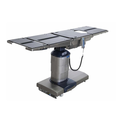
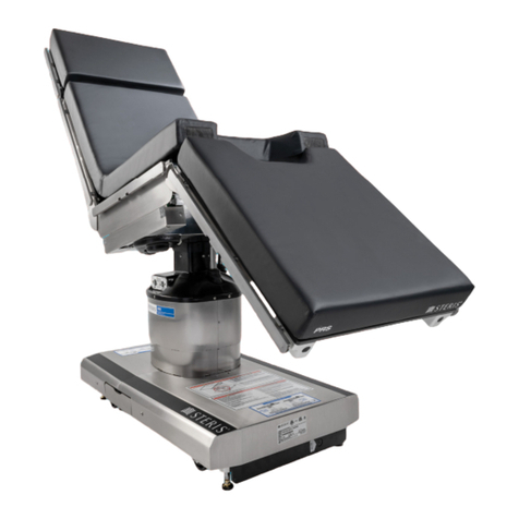
Motorized tabletop is constructed of four-sections (not
including the motorized fully radiolucent Kidney elevator
mechanism) and is 83" (2098 mm) long. Motorized Zip-Slide
movable tabletop eliminates the need for patient reorientation
and preconfiguration of the table. Unobstructed Imaging
Length of 63-1/2" (1613 mm) and 100% C-Arm access without
table movement is available. For attaching accessories, the
tabletop sections include a standard stainless-steel side rail
on both sides – located where they will not obstruct the imaging
area. Hook-and-loop fastener strips on the tabletop sections
permit instant application and removal of the 2" (51 mm) thick,
latex-free TLT mattress pad. The radiolucent tabletop sections
enable viewing of the entire anatomy (see illustration). The
easily attached X-Ray top design enables cassettes to be
loaded from the head, foot, or either side for a full range of
exposure angles.
Columnsupports tabletop and includes lift cylinders, bearings,
hydraulic piping, hydraulic actuators for Trendelenburg, tilt and
electrical wiring. These components are enclosed by six
telescoping stainless-steel column shrouds. The stainless-
steel shrouds are of two-piece construction for service
accessibility. Hand Control and optional Foot Control connect
at top of column.
Base structure is painted welded steel. The base cover is a
two-section, stainless-steel enclosure with a brushed finish.
Four large diameter swivel casters and a drive wheel inside the
base cover facilitate table relocation and movement. Four
mechanical, hydraulically operated, floor-locks are supplied.
The power supply assembly and floor lock actuators are also
within the base. Table power cord is plugged into a receptacle
centered on the base head-end cover. Master computer and
Backup Hand Control are also stored in the base behind a
cover plate. Included are: SLIDE HEAD/FOOT, HEIGHT UP/
DOWN, TREND./REV. TREND., TILT RIGHT/LEFT, BACK UP/
DOWN, LEG UP/DOWN, KIDNEY UP/DOWN, and LOCK/
UNLOCK switch.
Electric controlled system provides powered tabletop
positioning. Hydraulic actuators perform all powered table
motions (except Zip-Slide movable tabletop which is powered
by an electric motor). The primary control system is a master
computer located in the table base. This computer selects
which outputs are to be actuated based on inputs from an
auxiliary CPU in the pendant Hand Control and/or optional foot
control. The Hand Control is a tethered pendant that hangs
from standard side rails. Hand control provides user inputs
(from touch pad switches via an auxiliary CPU) to the master
computer. It also includes status LEDs and tabletop position
indicators. A Backup Hand Control, located in the table base,
and optional ACT Enabled interface to Operating Room Control
Systems (ORCS) enable all table actuations.
Electrical System (the input ac electrical power) is fed by a
detachable three-wire grounded power cord. An isolating
transformer and a rectifier circuit convert the power to 24 Vdc
for use by the operating and control systems. Fuses protect
the circuits from overloads. The Hand Control (an auxiliary CPU)
and optional foot control consist of switches that open or close
to signal the computer in the table column. The Hand Control
includes feedback LEDs. If ac main power fails, the battery
system can be used to power the table. The battery system is
activated by ensuring the Main Power Switch on the front of the
table base is ON and depressing any button on the Hand
Control. The batteries are continuously charging as long as the
table is supplied with the appropriate ac voltage and the Main
Power Switch is in the ON position.
Pendant Primary Hand Control is ergonomically designed. It
is constructed of two-piece injection molded thermoplastic
materials holding and sealing the auxiliary CPU and keypad.
The Hand Control is the primary interface for table operation
and the keypad is illuminated for easy table articulation
identification when room is dark. Hand Control is equipped with
a 7-1/2' (2.3 m) extended detachable long cord. The Hand
Control plugs into a receptacle located at the top of the column.
Dimensions are inches (mm). Society of
Automobile Engineers (SAE)measurements
are approximate based on metric dimensions.
Dimensions are typical -
drawing is not to scale.
Image Amplification Coverage (Typical)
Column
Column
41.4
(1051)
16
(395)
21.5
(546)
39.5
(1002)
16 (395)
18 (454)
24
(598)


