Endo Optiks E2 User manual

OPERATOR’S
MANUAL
OME 2000:
E2 COMPACT
MICROPROBE™ SYSTEM
English Operators Manual P/N: E2 Operators Manual CE
Rev. G October 6, 2014
For the
E2 Laser and Endoscopy System

TABLE OF CONTENTS PAGE
BEGINNING
Warning ……………….…………………………………………..…………...1
Labels ………………………………………………………………..……. 2-4
Precautions………………………………………………………..……… 5-6
SYSTEM OVERVIEW
System ....................................................................................... 7
Cabinet...................................................................................... 7
Light Source .............................................................................. 7
CCD Camera ............................................................................. 8
Digital Displays and Indicators .................................................. 8
Video Display............................................................................. 8
Foot Switch ............................................................................... 8
Front Panel................................................................................ 9
Back Panel ................................................................................ 10
Diode Laser and Principal of Operation ..................................... 11
GETTING READY
Site Preparation.......................................................................... 12
Utilities ...................................................................................... 12
Laser Safety ………………………………………………………………12-13
Reflection Hazard ....................................................................... 13
Tissue Protection........................................................................ 13
Explosion Hazard ....................................................................... 13
Vapor Plume............................................................................... 14
Exposure Protection from the Aiming Beam Laser....................... 14
Safe Viewing Times..................................................................... 14
Safety Features ………………………………………………………….14-15
CLEANING AND STERILIZATION
Cleaning the Laser Console ........................................................ 16
Cleaning the Laser Connector..................................................... 16
Cleaning the Video Adapter ........................................................ 16
Endoscope and Probe Cleaning and Sterilization......................... 16
CLINICAL APPLICATIONS
Indications for Use ..................................................................... 17
Glaucoma .................................................................................. 17
Vitreoretinal Surgery .................................................................. 17
Contraindications....................................................................... 18

Table of Contents (Cont.)
OPERATION
Set Up and Operation………………………………………………………19
Endoscopes and Probes .............................................................. 19
Inspection of the Optical System................................................. 19
Eye Insertion and Videography ................................................... 20
Eye Endophotocoagulation ......................................................... 20
Front Panel Features .................................................................. 20
Emergency Off............................................................................ 20
Standby ..................................................................................... 20
Enable........................................................................................ 21
Aiming Beam Push Button ......................................................... 21
Laser Power Push Button ........................................................... 21
Laser Duration Push Button....................................................... 21
Laser Output Power Control ....................................................... 22
Counter Display ......................................................................... 22
Counter Reset Push Button ........................................................ 22
Preliminaries .............................................................................. 22
System Turn-on ......................................................................... 23
Setting of the Treatment Beam ................................................... 23
Before Firing the Laser .............................................................. 23
Firing the Laser .......................................................................... 24
Setting Single Exposure Time ..................................................... 25
Between Patient Treatment and System Turn off......................... 25
MAINTENANCE AND TROUBLESHOOTING
Endoscope Maintenance ............................................................. 26
Laser Maintenance …………....................................................... 26
Laser Power Calibration ………………………………………………….. 27
Maintenance and Troubleshooting Guide………………………….28-30
Operator Replaceable Parts………………………………………………..30
TECHNICAL SPECIFICATIONS ……..…………………………………… 31-32
EMC GUIDELINES…………………………………..……………………………33-36
BIBLIOGRAPHY……………………………………………………………………37-42
ECP TREATMENT SUGGESTIONS................................................... .43
QUICK SET UP GUIDE........................................................................ .44

1
E2 COMPACT MICROPROBE
MICROENDOSCOPE SYSTEM
Endo Optiks, Inc.
39 Sycamore Avenue
Little Silver, NJ 07739-1208
USA
Tel: 001 732-530-6762 Fax: 001 732-530-5344
Website: http://www.endooptiks.com
Advena Ltd. Pure Offices, Plato Close, Warwick, CV34 6WE UK.
WARNING: NO UNAUTHORIZED USE OF LASER. The user of the E2
MicroProbe should be thoroughly trained in the applicable procedure.
Furthermore, failure to read and thoroughly understand the content of this
Operators Manual may result in serious injury to the patient or user. It is
essential to follow the instructions contained in this manual which pertain to
the E2 MicroProbe and accessories used in conjunction with the procedures.
Failure to follow these instructions may result in damage to the E2
MicroProbe or malfunction of the E2 MicroProbe.
CAUTION: Endo Optiks restricts the sale of the E2 MicroProbe to a physician
or on order of a physician.
E2 Operators Manual CE Rev. G September 12, 2014
2
BEGINNING
Labels
The following labels are affixed to the E2 Microprobe system. The title, the part
number, and the location on the E2 Microprobe are given for each label.
Label Location
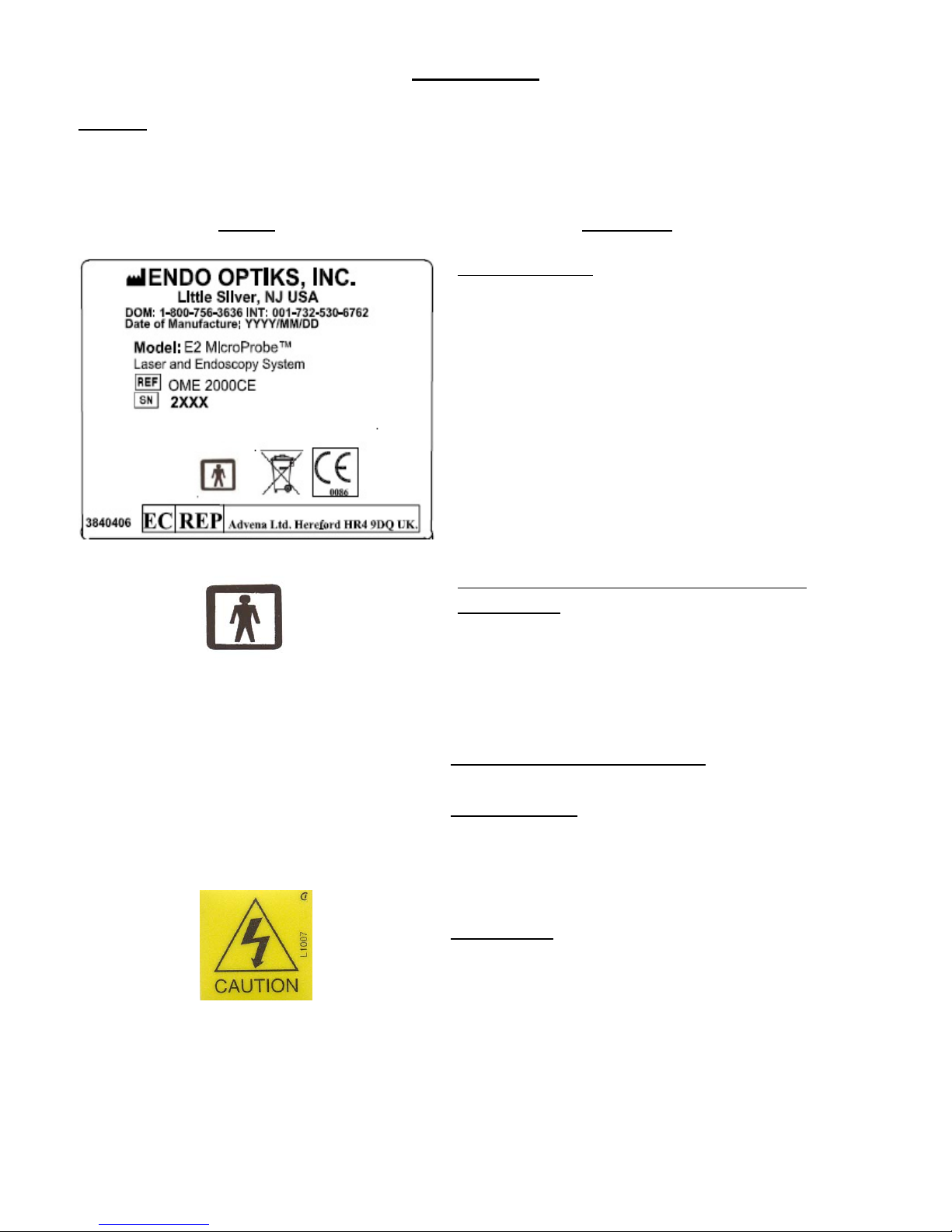
Identification
P/N 3840406
Rear Panel, near the top right corner.
Meaning: Type BF equipment
Protection Against Electric Shock
P/N L1012
Incorporated into the Identification
label
Supply Rating
115/240 Volts, 60/50Hz, 6.0/3.0A
Use 2 Type T6.3A, 250V
Fuse Replacement Label
P/N 0711111
Rear Panel, directly below AC
receptacle
Meaning: Dangerous Voltage
P/N L1007
Incorporated into the Identification
label

3
BEGINNING
LASER APERTURE
P/N L1003C
Front Panel
Caution: Consult Accompanying
Documents
P/N L1009
Incorporated into the Identification
label
This product conforms to the applicable
Requirements of US 21 CFR, subchapter J, FDA
Laser Notice 45, Laser Guide: 1995,
and IEC 60825-1:2007
LASER WARNING
P/N L1002C
Top, Front
CONFORMITY & APPLICABLE
STANDARDS
P/N L1016
Rear Panel
LASER STOP
P/N L1017
Front Panel
Conforms to European Medical
Device Directive 93/42/EC.
P/N L1003
Incorporated into the Identification
label
4
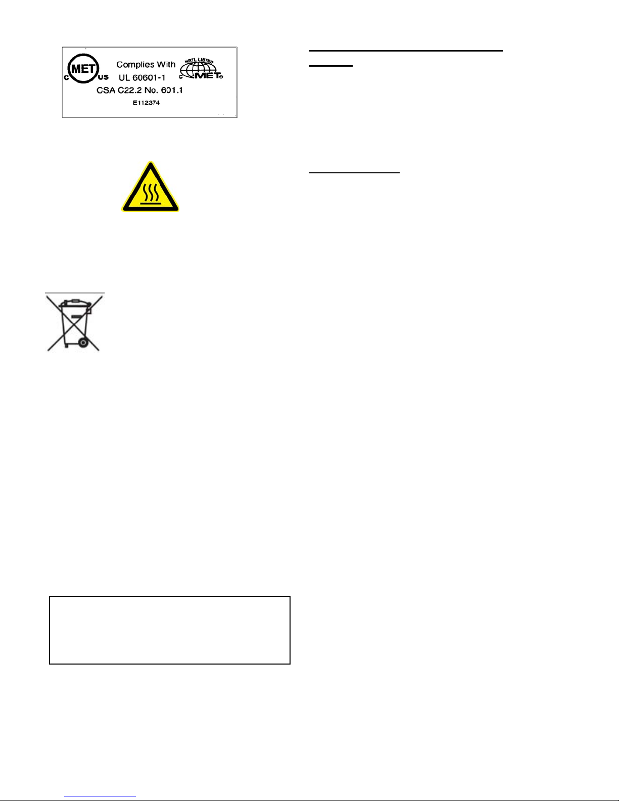
Safety Agency Approvals (MET
MARK)
P/N E112374
Rear panel, bottom left, under AC
receptacle
Caution: HOT
P/N: L1009A
Front Panel, next to light connector
when 300W light installed
This symbol has been attached to the equipment or, in the case that this is not possible,
on the packaging, instruction literature and/or the guarantee sheet. By using this symbol it states
that the device has been marketed after August 13th 2005, and implies that you must separate
all of its components when possible, and dispose of them in accordance with local waste
disposal legislations.
- Because of the substances present in the equipment, an improper use or disposal of the
refuse can cause damage to human health and to the environment.
- With reference to RAEE (Registry of Electrical and Electronic Apparatuses), it is
compulsory not dispose of the equipment with normal urban refuse, arrangements
should be instigated for separate collection and disposal.
- For more detailed information about recycling of RAEE, please contact your local waste
collection body.
- In case of illicit disposal, sanctions will be levied on transgressors.
Hospital Grade Power Cord
P/N: Hospital Grade Labels
Above Power Receptacle On Rear Panel
To achieve proper grounding reliability,
a power supply plug must be fully inserted
into a receptacle marked "HOSPITAL GRADE"

5
BEGINNING
Precautions
To prevent fire or shock hazard, do not expose the unit to rain or
moisture.
Dangerously high voltages are present inside the E2 Microprobe. Do not open
the cabinet. Refer servicing to qualified personnel only.
In the event of a malfunction or when maintenance is necessary, consult:
Endo Optiks
39 Sycamore Ave., Little Silver, NJ, USA.
Tel: 001 732 530 6762, Fax: 001 732 530 5344
Email: [email protected]
On safety
Operate the unit on the designated AC voltage only.
The Fuse Replacement Label indicates operating voltage and is located
adjacent to the mains fuse holder in the rear of the cabinet.
Should any solid object or liquid fall in, unplug the unit and have it checked
by qualified personnel before operating it any further.
To disconnect the AC power cord, pull it out by grasping the plug, never pull
the cord itself.
The outlet shall be installed near the equipment and shall be easily
accessible.
Warning
This equipment/system is intended for use by healthcare professionals only. This
equipment/system may cause radio interference or may disrupt the operation of
nearby equipment. It may be necessary to take mitigation measures, such as
reorienting or relocating the E2 Microprobe or shielding the location.
Endoscopes and Probes
This device is intended to be used in conjunction with Endo Optiks endoscopes
and probes ONLY and to assure safety should not be connected or used with
any other devices.
Disconnect the endoscope from the system by grasping the connectors only. Do
not grasp or bend the endoscope jacketing for this may break the glass fibers
that are enclosed within the jacketing.

6
CAUTION: The heat generated by the light source varies and can be hot causing
the light connector, on the endoscope, to become hot. To prevent injury to the
operator the light intensity should be turned down so the connector can cool
before removing it from the system.
On installation
The E2 MicroProbe should be used in a Hospital or Clinical setting only. It
should be used indoors only under the environmental conditions stated on
Page 36 of this document.
Allow adequate air circulation to prevent internal heat build-up.
Do not place the unit on surfaces (rugs, blankets, etc.) or near materials
(curtains, draperies) that may block the ventilation holes.
Do not install the unit in a location near heat sources such as radiators or
air ducts, or in a place subject to direct sunlight, excessive dust, mechanical
vibration or shock.
On cleaning
To keep the unit looking brand-new, periodically clean it with a mild detergent
solution. Never use strong solvents such as thinner or benzine, or abrasive
cleansers since they will damage the cabinet. As a safety precaution, unplug
the unit before cleaning it.
On sterilization before use
WARNING - The endoscopes and probes must be sterilized before use.
Please refer to the instructions provided with each device.

7
SYSTEM OVERVIEW
System
The Endo Optiks E2 MicroProbe is the principal component in a new portable
laser and endoscopy system. The complete system consists of the therapeutic
laser, the endoscope, the monitor and the footswitch. This compact unit creates
the opportunity to simultaneously image and photocoagulate the ciliary
processes through a corneal incision. It is especially indicated for the safe and
effective treatment of glaucoma in combination with cataract surgery. Important
vitreo-retinal applications can be realized. It can be used for the contact and
non-contact excision, hemostatis, incision and vaporization of soft tissue.
Cabinet
The compact laser and endoscopy cabinet houses a xenon light source, a
therapeutic laser and a CCD camera. The laser output, pulse width, light and
aiming beam intensity are controllable from the Front Panel. The parameters
are displayed on Front Panel digital displays and lighted status indicators. For
safety there is an emergency shutoff button. The Rear Panel features
connectors to any video monitor, VCR or video printer. A Foot Pedal enables
hands-free operation.
Light Source
The xenon light source is used to provide light to the endoscope. The intensity
of light can be adjusted from the Front Panel, or with the foot switch.
CAUTION: The heat generated by the light source varies and can be hot causing
the light connector, on the endoscope, to become hot. To prevent injury to the
operator the light intensity should be turned down so the connector can cool
before removing it from the system.

8
SYSTEM OVERVIEW
CCD Camera
The CCD camera is used to process the image obtained by the fiberoptic
endoscope and display it on the video display. There is a Video Camera BNC
connector Input and Outputs located at the Back Panel. The Video Camera
Cable Output can be plugged into the Video Camera Cable Input or a remote
Video Camera Cable Input can be used.
Digital Displays and Indicators
The Display consists of four Light Emitting Diodes and four Lighted Indicators.
They are as follows:
FUNCTION DISPLAY TYPE Key*
Laser Power Digital 1
Laser Active Lighted 2
Laser Duration Digital 3
Laser Standby Lighted 4
Laser Enable Lighted 5
Laser Aiming Power Digital 6
Laser Cool Down Lighted 7
Laser Shot Counter Digital 8
* Please refer to the Diagram labeled Front Panel on Page 8.
Video Display
The video display can be any high resolution monitor such as the Sony LMD-
1530MD and is used for displaying the endoscopic image. The video outputs
are located at the Back Panel and can be utilized for recording the endoscopic
image onto any video recording format such as the U.S. standard NTSC or the
European standard PAL. There is an S-Video (Y/C Out) and 4 Video Out
Connectors). All are BNC connectors (75 ohms terminated).
Foot Switch
The footswitch is used to activate the laser. Some footswitch models can also
be used to vary the illumination intensity of the xenon light source. The
footswitch connector is located at the Back Panel.
9
SYSTEM OVERVIEW
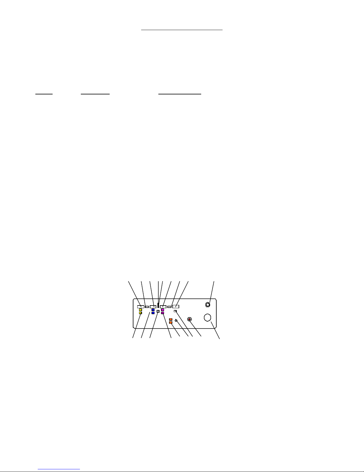
Front Panel
The Front Panel contains the color coded switches, digital displays and
indicators used to control the functioning and show the status of the E2
Microprobe. The functions and status indicators are:
KEY
COLOR FUNCTION
1 Laser Power Digital Display
2 Laser Active Lighted Indicator
3 Laser Duration Digital Display
4 Laser Standby Lighted Indicator
5 Laser Enable Lighted Indicator
6 Laser Aiming Power Digital Display Counter
7 Laser Cool Down Lighted Indicator
8 Laser Shot Counter Digital Display
9 Laser Output Connector
10 Yellow Laser Power Up and Down Switch
11 Blue Laser Duration Up and Down Switch
12 Green Laser Enable Switch
13 Red Aiming Beam Intensity Up and Down Switch
14 White Illumination Intensity Up and Down Switch
15 Xenon Lamp Out
16 Counter Reset
17 Red STOP (Big Red Button)
18 Camera
1 2 3 4 5 6 7 8 9
10 11 12 13 14 15 16 17 18
Front Panel Features
10
SYSTEM OVERVIEW
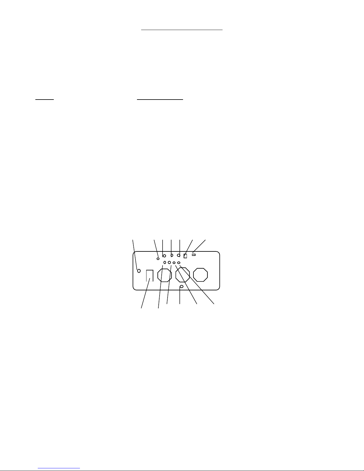
Back Panel
The Back Panel contains the On -- Off Key Switch, the Mains Power Inlet, the Fuses,
the Foot Switch Connector, the Video Connectors, the Remote Interlock and the
Remote Communications Port. The locations are:
KEY FUNCTION
1 Video Camera Cable (located under the cabinet foot)
2 Video Camera Cable Input
3 S-Video (Y/C Out)
4 Foot Switch
5 Remote Interlock
6 Laser On -- Off Key Switch
7 RS-232 Remote Communications Port
8 ON/OFF Switch and Mains Power Inlet and Fuses
9 Video Out
10 Video Out
11 Fuse for Lamp Power Supply
12 Video Out
13 Video Out
1 2 3 4 5 6 7
8 9 10 11 12 13
Back Panel Layout

11
SYSTEM OVERVIEW
Diode Laser and Principal of Operation
Diode lasers are small semiconductor devices consisting of a sandwich of
gallium-aluminum arsenate crystalline materials and end mirrors. The
electrons of the crystal are raised to an excited energy state by an electrical
current. When the electrons return to their original energy state, photons are
emitted. In the laser cavity, these emitted photons are trapped between the
cladding layers and the end mirrors. When a photon passes close to an excited
electron, the electron will be stimulated to emit another photon that is identical
in wavelength and phase to the first. This amplification process continues,
increasing the number of active photons as the photon light beam is reflected
back and forth between the cavity mirrors. One of these mirrors releases a
percentage of the energy hitting its surface resulting in the infrared laser light.
The frequency of the diode laser employed in this system is 810nm. This laser
is intended only for the use of physicians who are trained in operation of laser
photocoagulators. Training in the therapeutic use of lasers is available in
medical courses and seminars offered throughout the world.

12
GETTING READY
Site Preparation
The E2 Microprobe system has no special electrical or water requirements.
Standard wall voltage can be utilized and no special cooling is required because
a solid state diode laser is used.
Utilities
Electrical: The E2 Microprobe can be configured to operate from a power
source in the range of either 115 volts AC or 240 volts AC, 60/50Hz, 690/720
watts maximum. A standard grounded AC outlet is sufficient. Verify that the
voltage indicated on the fuse holder, below the A/C receptacle, at the back of
the laser console matches the actual line voltage before the instrument is
plugged in.
WARNING
This equipment/system is intended for use by healthcare professionals only. This
equipment/system may cause radio interference or may disrupt the operation of
nearby equipment. It may be necessary to take mitigation measures, such as
reorienting or relocating the E2 Microprobe or shielding the location. Refer to EMC
Guidance in the Technical Specifications section.
WARNING
No modification of this equipment is allowed.
WARNING
Do not modify this equipment without authorization of the manufacturer.
WARNING
If this equipment is modified, appropriate inspection and testing must be conducted to
ensure continued safe use of the equipment.
Laser Safety
WARNING - Never look directly into the laser aperture (output port) or
fiberoptic when power is applied. Severe eye damage could occur.
As a precaution against accidental exposure to the output beam or its
reflection, all persons in the vicinity during operation of the photocoagulator
must wear laser safety glasses. The only exception is the surgeon if he or she is
looking through a delivery system which is protected by an internal laser filter.

13
Never look directly into the laser beam or its reflection, even with the laser
safety glasses in place. The laser safety glasses must give protection at 810NM.
Note: The Endo Optiks diode laser safety glasses have been tested and are compliant
with EN60207-EN60208 standards. The 810nm wavelength and Optical Density (O.D.)
of 5+ are clearly indicated on the laser safety glasses. Safety glasses that are obtained
from any vendor other than Endo Optiks should be compliant with these standards.
Some multiwavelength glasses will block the aiming beam and laser firing indicator, on
the front panel of the system and should not be used.
Reflection Hazard
Smooth objects will reflect a diode laser beam. Reflection hazards can exist
beyond the laser beam aperture. Regardless of the surface, reflection is a
potential hazard when the laser strikes a nonabsorbent surface such as a
metallic instrument. There are two types of reflections which can occur:
Specular and diffuse.
Specular reflections: Specular reflection occurs when the size of the surface
irregularities is less than the wavelength of the incident radiation. In this
instance the laser beam reflects at the same angle as the angle of incidence.
The danger occurs when a concentrated beam of laser light could accidentally
strike unintended tissue or the eyes causing significant thermal damage.
Diffuse reflections: Diffuse reflection occurs when surface irregularities are
randomly oriented and are much greater than the wavelength of the incident
light. In this instance the reflected laser beam is disorganized and scatters in
many directions though a laser light may still strike an unintended target
surface. But the power density will be reduced to a degree that will cause
minimal, if any, thermal effect.
Tissue Protection
WARNING - Never place your hand or other objects in the pathway of the
laser beam. Severe burns could occur.
Explosion Hazard
WARNING - Never operate the laser in the presence of flammable
anesthetics. An explosion and fire could occur.
Do not use the laser in the presence of flammables or explosives such as volatile
anesthetics, alcohol, certain surgical preparation solutions and other such
substances.
The E2 MicroProbe laser should be disabled whenever the system is not
actually in use during treatment of a patient. To safely disable the laser the
key should be removed from the rear panel of the system. This is to prevent
accidental laser discharge if the Foot Pedal is inadvertently depressed

14
GETTING READY
Vapor Plume
CAUTION: Laser plume may contain viable tissue particulates; however the
endoscope is fired in a closed environment in both the anterior and
posterior segments of the eye so the plume does not escape into the
atmosphere. There are no possible hazards associated with the laser
plume.
Exposure Protection from the Aiming Beam Laser
CAUTION: The maximum safe power that can be visualized indefinitely by the
retina is 0.39 microwatts (Class 1). The diode laser that produces the red
aiming beam is a Class 3R laser, producing up to 1,500 microwatts. Direct
visualization of Class 3R laser radiation by a patient during treatment has not
been shown to be safe. To protect the patient from possible retinal damage use
the lowest practical aiming beam intensity during treatment. The diode laser
produces a red diode aiming beam with power variable from barely visible to 1.5
milliwatts maximum. The safe (Class 1) exposure duration limit at maximum
power level of 1.5 milliwatts is 0.047 seconds.
Safe Viewing Times
Class
Description Type
1
Safe under conditions of operation.
2
Eye protection by aversion response
(blink).
3
Minimum safe viewing time.
Aiming Laser
4
Use requires extreme caution. Treatment Laser
Safety Features
Key Lock Switch: The laser can be turned on only with the proper key to close
the master switch. The key cannot be removed in the On position and the laser
will operate only when the key is in place. When the Key Switch is rotated to
the On position, power is available to the instrument. For safety purposes, the
key should be removed when the laser is not being used.
Enable Function: Even when the E2 MicroProbe is activated by turning the
key on, the Foot Pedal will not fire the laser. The laser cannot be fired unless
the ENABLE control is pressed on. This control takes the laser out of the

15
STANDBY mode and allows laser firing by footswitch activation. This safety
feature requires a deliberate second action by the Operator of the laser prior to
its being fired.
Protective Housing: The diode laser has a protective housing which prevents
unattended human access to laser radiation above safe limits. The user shall
not perform maintenance or service operations inside the protective covers.
This housing is to be opened only by an Endo Optiks Service Representatives or
an Endo Optiks certified technician.
Protective Jacketing: The laser fiber inside the endoscope is protected by
jacketing. In the event that the laser fiber breaks, the jacket protects the user
from laser radiation emission.
Viewing Optics: When employing the laser endoscope in the Video mode, direct
viewing of the laser and ocular tissues is not an issue, because the laser energy
cannot be emitted through the video display.
Room Door Interlock: The E2 MicroProbe will be switched into standby mode
when the treatment room door is opened during use.
System Labels: Appropriate warning labels have been mounted in specified
locations on the instrument to indicate conditions under which the user could
be subjected to laser radiation.
STOP: Depressing the STOP (the Big Red Button) will immediately disable the
laser and reset all the treatment parameters to zero. The E2 MicroProbe will
be in the stand-by mode with the power on.
WARNING
It is not intended that the user perform any maintenance or service
operations inside the protective housing of the diode laser. All internal
adjustments, cleaning, maintenance, and servicing shall be performed only
by an Endo Optiks Service Representative or an Endo Optiks certified
technician.
CAUTION
Use of controls or adjustments or performance of procedures other than
those specified herein may result in hazardous radiation exposure.

16
CLEANING AND STERILIZATION
Cleaning the Laser Console
To clean the external surface of the Laser Console, wipe using a cloth dampened
with a noncaustic cleaning solution such as soap and water, isopropyl alcohol
or a "hospital grade" disinfectant. Do not spray or put cleaning agents directly
on the system. Dry with a clean, dry cloth or allow to air dry.
Cleaning the Laser Connector
Before connecting an endoscope to the system, clean the tip of the Laser
Connector with alcohol and lens cleaning tissue. Moisten the lens tissue with
alcohol and gently wipe it once across the tip of the Laser Connector.
Cleaning the Video Adapter
Before connecting an endoscope to the system, clean the tip of the Video
Connector with alcohol and lens cleaning tissue. Moisten the lens tissue with
alcohol and gently wipe it once across the tip of the Laser Connector. This will
prolong the life of the endoscope and maximize image quality.
Clean the Video Adapter with a lens cleaning tissue. Do not use alcohol for this
may harm the laser filter that is built into the Video Adapter.
Endoscope and Probe Cleaning and Sterilization
These devices are delivered non-sterile and are designed to be reusable in
accordance with the constraints described in the information supplied. The
Endoscope should be sterilized before each use. If the endoscope is sterilized
but not cleaned after each use, you will almost certainly destroy the tip of the
endoscope the next time you fire the laser.
FULL INSTRUCTIONS FOR CLEANING AND STERILIZATION ARE PROVIDED
WITH EACH ENDOSCOPE OR PROBE.

17
CLINICAL APPLICATIONS
WARNING
The MicroProbe system is intended solely for use by physicians trained
in the operation of laser photocoagulators.
Indication For Use
The ophthalmic laser endoscope is indicated for the Endo intraoperative
photocoagulation of the ciliary processes in the treatment of glaucoma,
proliferative retinopathies, retinal detachment, focal treatment of retina or
choroidal disorders, and for evaluation of the internal ocular structures in
patients with dense opacifications of the anterior segment which do allow a
posterior view.
Glaucoma
This instrument is indicated for the treatment of glaucoma in patients who have
failed with conventional topical and systemic medications, or previous laser
photocoagulation, or trabeculectomy and other filtering procedures, or
cyclocryotherapy or other cyclodestructive procedures.
The endophotocoagulation of ciliary processes under direct endoscopic view is
highly controllable, i.e. titratable, and has been demonstrated to be effective in
the treatment of glaucoma.
Vitreoretinal Surgery
The endoscopically controlled endophotocoagulation that is possible with the
ophthalmic laser endoscope is also useful for endophotocoagulation:
During vitreous surgery to produce chorioretinal scar around retinal breaks
or retinotomy sites
To perform intraoperative panretinal photocoagulation (PRP) in
proliferative retinopathies
To perform intraoperative retinal photocoagulation on a scleral buckle
To perform intraoperative photocoagulation around focal
neovascularization
Table of contents


