Teptron MOVEZ User manual

MOVEZ
User manual
MOVEZ- Z-Wave controlled motor for indoor blinds and shades

2
Table of Content
1WARNINGS AND GENERAL PRECAUTIONS FOR SAFETY ...................................................................................................... 3
1.1 INSTALLATION WARNINGS ........................................................................................................................................................ 3
1.2 USE WARNINGS...................................................................................................................................................................... 3
2REGULATORY AND SAFETY NOTICES .................................................................................................................................. 4
3ABOUT THE PRODUCT ........................................................................................................................................................ 5
3.1 PRODUCT SPECIFICATIONS ........................................................................................................................................................ 5
3.2 PRODUCT IMAGES................................................................................................................................................................... 5
4INTEROPERABILITY............................................................................................................................................................. 7
5INCLUSION INTO THE Z-WAVE NETWORK .......................................................................................................................... 7
6EXCLUSION FROM THE Z-WAVE NETWORK ........................................................................................................................ 7
7SMARTSTART ..................................................................................................................................................................... 7
8FORCE RESETTING THE DEVICE ........................................................................................................................................... 8
9DEVICE BASIC FUNCTIONALITY........................................................................................................................................... 8
10 MULTILEVEL COMMAND CLASS IMPLEMENTATION ........................................................................................................... 8
11 MULTILEVEL SWITCH COMMAND CLASS, VERSION 3.......................................................................................................... 9
12 SUPERVISION COMMAND CLASS IMPLEMENTATION ......................................................................................................... 9
13 ASSOCIATIONS ................................................................................................................................................................... 9
14 CONFIGURATION PARAMETERS ....................................................................................................................................... 10
15 DEVICE CLASSIFICATION................................................................................................................................................... 11
16 SUPPORTED COMMAND CLASSES .................................................................................................................................... 11
17 FLIRS?............................................................................................................................................................................... 11
18 LOCAL SWITCH OPERATIONS............................................................................................................................................ 12
19 LOW BATTERY WARNINGS ............................................................................................................................................... 12
20 LED INDICATIONS MAIN DEVICE....................................................................................................................................... 12
21 BATTERY PACK ................................................................................................................................................................. 13
22 ALTERNATIVE POWER SOURCE......................................................................................................................................... 13
23 SOLAR PANEL ................................................................................................................................................................... 13
24 CALIBRATION OF ENDPOINTS........................................................................................................................................... 14
25 INSTALLATION OF THE MOTOR AND THE ACCESSORIES ................................................................................................... 15
26 BEAD CHAIN INSTALLATION ............................................................................................................................................. 16
26.1 MOUNTING BEAD CHAIN TO PULLEY ......................................................................................................................................... 16
26.2 ATTACHING BEAD CHAIN ........................................................................................................................................................ 16
27 CORD LOOP INSTALLATION .............................................................................................................................................. 17
27.1 MOUNTING CORD LOOP TO PULLEY .......................................................................................................................................... 17
27.2 ATTACHING CORD LOOP......................................................................................................................................................... 17
28 PLAIN CORD INSTALLATION ............................................................................................................................................. 18
28.1 MOUNTING CORD TO THE SPOOL ............................................................................................................................................. 18
28.2 ATTACHING CORD................................................................................................................................................................. 18
29 WAYS TO GET CORRECT POSITION FOR INSTALLATION .................................................................................................... 19
30 INSTALL MOUNTING PLATE.............................................................................................................................................. 21
31 ATTACH MAIN DEVICE TO MOUNTING PLATE .................................................................................................................. 22
32 INSTALLING BATTERY PACK.............................................................................................................................................. 23
33 DISPOSAL AND RECYCLING INFORMATION ...................................................................................................................... 24

3
1Warnings and general precautions for safety
Read these warnings carefully before you continue installing, connecting and using MOVEZ hereinafter called the product. It is very important that you follow
the safety and warning instructions written in this manual to ensure a safe use of the product. Keep these instructions. Heed all warnings. Only use the product
as described in these instructions.
WARNING: Failure to follow these safety instructions could result in fire, electric shock, or other injury or damage to the product or other property.
1.1 Installation warnings
The product installation, collection programming and maintenance operations must be carried out exclusively by a qualified adult in observance of the instructions in this
manual.
Before starting installation make sure the product can be retrofitted to your type of indoor blinds and shades. If not suitable do NOT proceed with installation. Make sure
the product is able to run without risks of entangling, also make sure that anything in the vicinity is within such risk.
The product installation and maintenance operations must be performed with all power sources disconnected from MOVEZ.
Install the product out of reach for children. The product shall not and cannot replace the purpose of a child safety product for indoor blinds and shades. The product and
its accessories may contain small parts. Keep them away from small children.
It is very important NOT to use the product with battery power if it must be placed in direct sunlight or near other heat sources, in high temperatures batteries can be
dangerous. In these conditions always remove the batteries and use a suitable USB power adapter to power the product. Exact specification for the USB power adapter can
be found in this manual. Read all safety instructions for any other products and/or accessories before using with the product. Teptron AB is not responsible for the
operation of, or any damage caused by, third-party accessories or their compliance with safety and regulatory standards.
During installation, handle the product with care - avoid crushing, impact, dropping or contact with liquids - never place the product near sources of heat or expose to
naked flames. All these actions could damage the product and cause malfunctions or dangerous situations.
Pay attention to your personal safety in regard to proper use of ladders. Be careful when handling tools from an extended height, do not drop them. Do not drop the
product. If dropped or damaged do not install it. Be aware of that a dropped product may not have visibly detectable damage.
Be very careful when handling knifes, scissors or similar sharp cutting tools.
Do not install the product to outdoor shading products, its only intended to be applied to indoor blinds and shades.
Do not dismantle the product other than described in this manual. Do not make any changes to any part of the product except those indicated in this manual. Do not insert
anything in the product except what’s described in this manual. The manufacturer declines all liability for damage caused by makeshift modifications to the product.
Before connecting a power adapter, batteries or blinds and shades to the product, carefully read the warnings and the product manuals of those products, and it’s
important to only use approved certified products.
When connecting a power adapter to the product do not use a damaged power cord or plug and do not use loose or damaged power outlets. Unplug power adapter during
lightning storms or when unused for long periods of time.
Protect the power cord from being walked on or pinched, particularly at plugs, convenience receptacles, and the point where they exit from the apparatus.
1.2 Use warnings
Do not operate the product when jobs are being performed in the vicinity i.e. window cleaning, maintenance jobs, etc. Disconnect the all power supplies to the product
before starting such jobs. Be aware of operating the product when your window is open. Outside circumstances may cause damage to the product and the surroundings.
Keep the product out of reach for children. The product may attract attention of children and animals. During operation children and animals should be kept away from the
device.
Do not pull the cord, cord loop or bead chain when the product is attached to and installed in active or passive mode.
Wash yourself immediately if exposed to battery acid.
Always shield the product from direct sunlight regardless of power source.
Make sure that your burglar alarm does not trigger because of movement from your blinds or shades
After commissioning, the batteries are trickle-charged by electrical energy generated by the solar panel. The energy produced by the solar panel is stored in Li-iron
batteries. It is normal for the battery to gain more energy in summer as compared to winter. The solar panel converts the intensity of light to energy when available.
If the motor does not operate due to an excessively diminished battery, the battery pack may require a full recharge by battery charger that is approved by manufacture. If
the battery no longer provides adequate power to operate the motor, new rechargeable battery pack should be installed.
Always read instructions on how to install and remove battery pack to and from MOVEZ main device.
Never force a connector into a port when using connectors and ports. Check for obstructions on the port. If the connector and port don’t join with reasonable ease, they
probably don’t match. Make sure that the connector matches the port and that you have positioned the connector correctly in relation to the port.
Refer all servicing to qualified service personnel. Service is required when the apparatus has been damaged in any way, such as when the solar panel cord or plug is
damaged, liquid has been spilled or objects have fallen into the apparatus, the apparatus has been exposed to rain or moisture, dose not operate normally, or has been
dropped.
Do not use the product in rain, or near washbasins or other wet locations and avoiding water and wet locations. Take care not to spill any food or liquid on the product. In
case the product gets wet, unplug all cables and remove the battery before cleaning, and allow it to dry thoroughly before turning it on again. Do not attempt to dry the
product with an external heat source, such as a microwave oven or hair dryer. Damage to the product caused by contact with liquid is not covered by the manufacturer.

4
2Regulatory and safety notices
Model name: MZ1811
FCC warnings:
FCC Statement:
Any Changes or modifications not expressly approved by the party responsible for compliance could void the user’s
authority to operate the equipment.
This device complies with part 15 of the FCC Rules. Operation is subject to the following two conditions:
(1) This device may not cause harmful interference.
(2) This device must accept any interference received, including interference that may cause undesired operation.
FCC Radiation Exposure Statement:
This equipment complies with FCC radiation exposure limits set forth for an uncontrolled environment. This
equipment should be installed and
Operated with minimum distance 20cm between the radiator & your body.
ISED RSS Warning/ISED RF Exposure Statement:
ISED RSS Warning:
This device complies with Innovation, Science and Economic Development Canada licence-exempt RSS standard(s).
Operation is subject to the following two conditions: (1) this device may not cause interference, and (2) this device
must accept any interference, including interference that may cause undesired operation of the device.
Le présent appareil est conforme aux CNR d'ISED applicables aux appareils radio exempts de licence. L'exploitation
est autorisée aux deux conditions suivantes:
(1) l'appareil ne doit pas produire de brouillage, et
(2) l'utilisateur de l'appareil doit accepter tout brouillage radioélectrique subi, même si le brouillage est susceptible
d'en compromettre le fonctionnement.
ISED RF exposure statement:
This equipment complies with ISED radiation exposure limits set forth for an uncontrolled environment. This
equipment should be installed and operated with minimum distance 20cm between the radiator& your body.This
transmitter must not be co-located or operating in conjunction with any other antenna or transmitter.
Le rayonnement de la classe b repecte ISED fixaient un environnement non contrôlés.Installation et mise en oeuvre
de ce matériel devrait avec échangeur distance minimale entre 20 cm ton corps.Lanceurs ou ne peuvent pas
coexister cette antenne ou capteurs avec d’autres.
European Union (EU)
Declaration of Conformity with Regard to the EU Directive 1999/5/EC
Teptron AB is authorized to apply the CE Mark on MOVE, model name: MOVE MZ1811, thereby declaring conformity
to the essential requirements and other relevant provisions of Directive 1999/5/EC.
Compliant with the standard R&TTE 99/CE/05
Conforme à la norme R&TTE 99/CE/05
Konform mit dem Standard R&TTE 99/CE/05

5
3About the product
MOVEZ is intended exclusively for the automation of various types of indoor blinds and shades. MOVEZ is a motor
for existing indoor blinds and shades. It is built to fit as many different manually controlled indoor blinds and shades
as possible. Therefore the motor can be retrofitted to nearly all different manually controlled indoor blinds and
shades.
No matter if its continuous cord loops, bead chain loop, bead chin with connectors or just reeling in a cord MOVEZ
will be able to operate it. MOVEZ is installed enclosed wall bracket.
MOVEZ uses a Z-Wave radio and it is a Security (S2) & SmartStart enabled Z-Wave Plus Product. It uses S2
UNAUTHENTICATED SECURITY CLASS as its highest level of security. Hence a Security Enabled Z-Wave Controller
must be used in order to avail security features of the product.
3.1 Product specifications
•Main power source: Rechargeable battery pack
•Alternate power source: AC to DC switch mode power supply with output regulated to DC 8V 1.3A and a
micro USB type B connector
•Radio protocol: Z-wave
•Motor torque: ≈1Nm (lift/pull capacity: 10kg/22lb)
•Size MOVEZ device: Length 110mm, width 38mm, height 49mm
•Size Battery device: Length 78mm, width 38mm, height 49mm
•Size solar panel: Length 238mm, Width 55mm
•Weight: 350
3.2 Product images
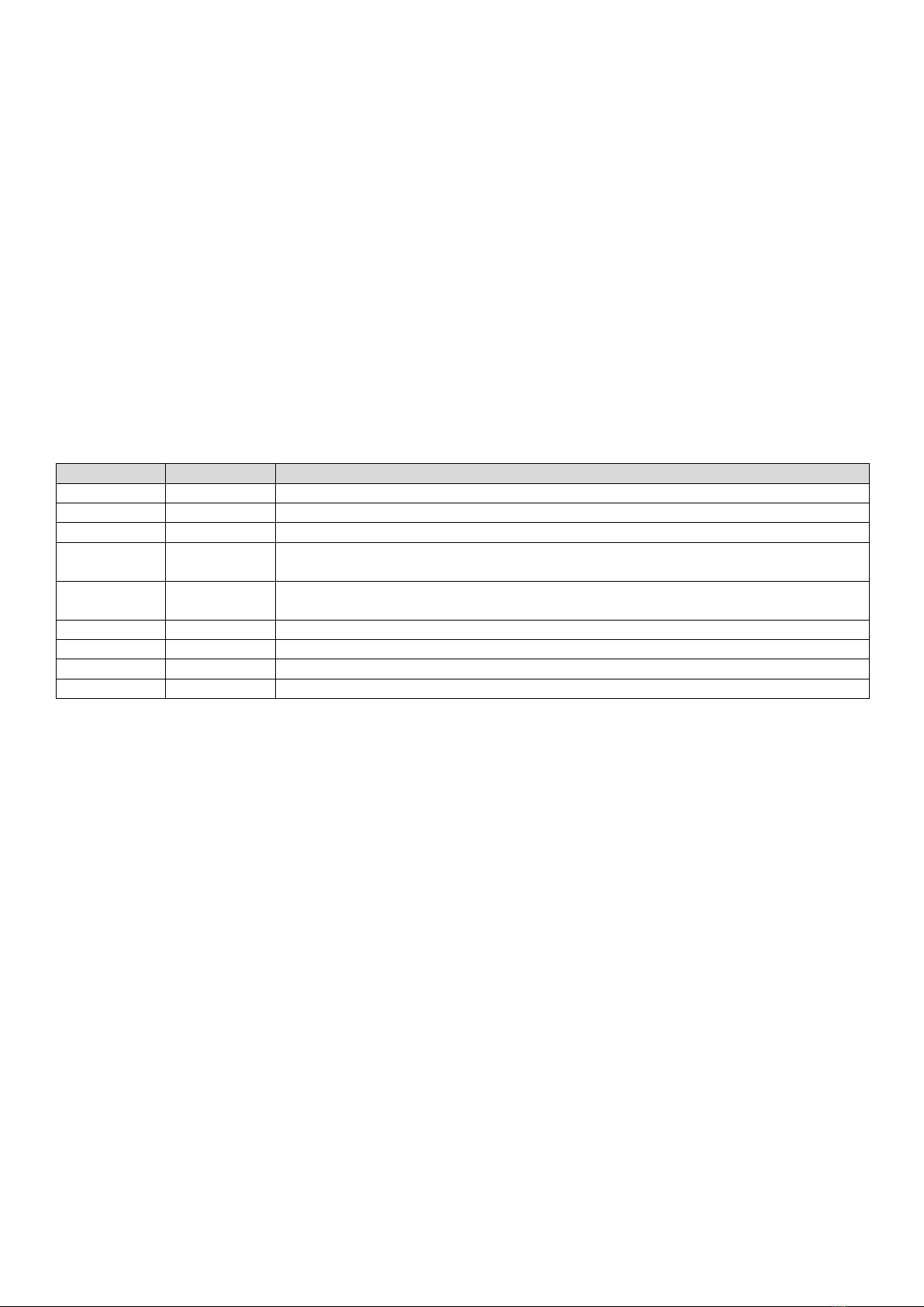
Picture 1-Product picture

6
Picture 2-Main device
Picture 3-Parts

7
4Interoperability
This product can be operated in any Z-Wave network with other Z-Wave certified devices from other manufacturers.
All non-battery-operated nodes within the network will act as repeaters regardless of vendor to increase reliability of
the network.
5Inclusion into the Z-Wave network
Inclusion is a process by which a new device (or a device which previously got out of Z-Wave network by force reset
or exclusion process) can join a new or existing Z-Wave network. Including procedure is shown below. Note: The
term “INCLUSION”, “ASSOCIATE”, “ADDING”, “PARING” implies to the same meaning.
Inclusion procedure explained below,
1. Set the gateway into inclusion mode (See gateway’s product manual for more information).
2. Set MOVEZ into learn mode. Learn mode is set by press and holding stop button (picture 2, position 2) for 10
plus seconds. Once both red and green led indicator start blinking together (picture 2, position 5), release
stop button to issue node information frame.
3. Because device supports S2 Unauthenticated Class gateway may ask for an option of secure or non-secure
inclusion. Please select this as per your preference.
4. Green led blink twice once inclusion process is successfully completed.
6Exclusion from the Z-Wave network
Exclusion is a process by which an already included device can be made to leave its existing Z-wave network. Upon
exclusion all user configuration parameters are set to their default values. Note: The term “EXCLUSION”,
“REMOVING”, “UNPARING” implies to the same meaning.
Exclusion procedure explained below,
1. Set gateway into the exclusion mode (See gateway user manual for more information)
2. Set MOVEZ into learn mode. Learn mode is set by press and holding stop button (picture 2, position 2) for 10
plus seconds. Once both red and green led indicator start blinking together (picture 2, position 5), release
stop button to issue node information frame.
3. Red led blink twice once exclusion process is successfully completed.
7SmartStart
Z-Wave SmartStart is a feature that removes the need for initiating the end device to start inclusion. With SmartStart
Inclusion is initiated automatically on power-ON and repeated at dynamic intervals for as long as the device is not
included into a Z-Wave network.
As the new device announces itself on power-ON, the protocol will provide notifications, and the gateway can
initiate the inclusion process in the background, without the need for user interaction or any interruption of normal
operation. This improvement also removes the possibility of other devices being included, as the SmartStart
inclusion process only includes authenticated devices. A gateway supporting SmartStart has a provision list for
adding device DSKs. As this device supports S2_UNAUTHENTICATED class of security, DSK or QR code not required
for manual inclusion of the device into the network, DSK or QR code is only needed when SmartStart feature is being
used. DSK or PIN code can be found on the backside of the device as well as on the packaging box. Do not remove
the “Z-Wave pin code” label from the product.

8
8Force resetting the device
The device has a provision to RESET itself. Once the device resets, it will no longer be a part of Z-Wave network and
all the user configuration parameters are set to their default values. Controller will be informed about this event
with COMMAND_CLASS_DEVICE_RESET_LOCALLY command via lifeline group so that node cleaning operation can be
started.
Device Reset can be invoked by press and holding stop button (picture 2, position 2) for 20 plus seconds. Once both
red and green blinking leds (picture 2, position 5) becomes stable ON release stop button.
Blinking of red led twice indicates that reset operation is successful.
Note: Red and green leds starts blinking after 10 plus seconds to indicate inclusion or exclusion can be activated at
that point if button is released.
9Device basic functionality
MOVEZ implemented with the support of Basic Command Class so that legacy devices can be able to control MOVEZ
with basic functionality. Below is the mapping shown,
Basic Set = 255 maps to Multilevel Switch Set = 99 (if value of configuration parameter 03, is set to 1)
Basic Set = 255 maps to Multilevel Switch Set = Last known non-zero value. (if value of configuration parameter 03, is
set to 0). See configuration parameters section for more information. Default last known value is 100%.
Basic Set = 0 maps to Multilevel Switch Set = 0
Basic Set = 1-99 maps to Multilevel Switch Set = 1-99
Basic Get/Report maps to Multilevel Switch Get/Report
Basic CC also supports securely.
10 Multilevel Command Class implementation
When sending a multilevel report to the gateway MOVEZ follow the below pattern,
Current value field always reports current position of the device reading from the hardware.
Target value field reports 99 if motor is moving towards opening and reports 0 if motor is moving towards closing
and reports same value as “Current value” when motor is not moving.
Duration field reports “Unknow Duration” if motor is moving in either direction and reports “Already at the target
value” if motor is not rotating.
Duration field of SWITCH_MULTILEVEL_SET and WITCH_MULTILEVEL_START_LEVEL_CHANGE command cannot be
used as limitation of this multilevel device that cannot make instant transitions to any location.
Value field of MULTILEVEL_SET version 4 command if received as 0xFF, will set curtain to last known non-zero
position. Default last known value is 100%.
Ignore Start Level field and Primary Switch Start Level fields of SWITCH_MULTILEVEL_START_LEVEL_CHANGE
command is ignored.

9
11 Multilevel Switch Command Class, Version 3
As Secondary Switch Type of the Multilevel Switch Command Class, version 3 has been DEPRECATED. Secondary type
switch, all its associated fields are also ignored. This device supports only primary switch as Open/Close.
Ignored fields are,
•“Secondary Switch Inc/Dec” field of SWITCH_MULTILEVEL_START_LEVEL_CHANGE command.
•“Secondary Switch Step Size” field of SWITCH_MULTILEVEL_START_LEVEL_CHANGE command.
12 Supervision Command Class Implementation
As this device supports S2 security class, Supervision command class is implemented for high level security reporting.
Because duration field is unknown when motor running MOVEZ follow the below reporting pattern,
•If motor is moving in either direction, an immediate report will be sent with,
1. Status filed reports “Working” with More Status Updates bit set to 1.
2. Duration field reports “Unknown Duration”.
3. After motor stops
4. Status filed reports “Success” with More Status Updates bit set to 0.
5. Duration field reports “Already at the target value”.
•If motor is not moving an immediate report will be sent with,
1. Status field reports “Success” with More Status Updates bit set to 0.
2. Duration field reports “Already at the target value”.
13 Associations
MOVEZ supports association command class with two association groups,
GROUP 01: Lifeline group, this group can accommodate only one node. Usually a gateway’s node ID configured
automatically by the gateway during interview process. All the system related communications like force resetting
device, low battery warning, curtain position (if changed locally via buttons) are notified to the gateway through
lifeline group.
GROUP 02: This group is to control its destination nodes using BASIC and MULTILEVEL command class. Group 02 can
accommodate maximum of five devices. Commands issued via this group can be configured using configuration
parameter 04, which is explained below, (See configuration parameters section for more information).
Configuration parameter 04 | Value 00 (Default)
Botton/Action
HOLD
RELEASE
UP Button
Basic Set FF
--
Down Button
Basic Set 00
--
Table 1
Configuration parameter 04 | Value 01
Botton/Action
HOLD
RELEASE
UP Button
Multilevel Set FF
Stop Level Change
Down Button
Multilevel Set 00
Stop Level Change
Table 2
Configuration parameter 04 | Value 02
Botton/Action
HOLD
RELEASE
UP Button
Start Level Change UP
Stop Level Change
Down Button
Start Level Change DOWN
Stop Level Change
Table 3

10
14 Configuration Parameters
MOVEZ support user configuration parameters so that user can set their preferences.
Parameter #01 –Set motor’s up speed
Size
1 byte (decimal)
Range
1 to 100
Default value
100
Description: Configures the up speed of the motor, 1=lowest and 100=highest speed.
Table 4
Parameter #02 –Set motor’s down speed
Size
1 byte (decimal)
Range
1 to 100
Default value
100
Description: Configures the down speed of the motor, 1=lowest and 100=highest speed.
Table 5
Parameter #03 –Basic Set 0xFF support
Size
1 byte (decimal)
Range
0 to 1
Default value
1
Description: The value of the parameter decides the behavior of BASIC SET support. Motor position sets to last known non-
zero value if value this parameter is set to 0. Motor position set to 100% if value this parameter is set to 1.
Table 6
Parameter #04 –Association group 02 control command preference
Size
1 byte (decimal)
Range
0 to 2
Default value
0
Description: The value of this parameter decides control commands to be used for association group 02. See Table 1,2, and
3 for more information.
Table 7

11
15 Device Classification
MOVEZ classified under,
Generic Device Class –GENERIC_TYPE_SWITCH_MULTILEVEL
Specific Device Class –SPECIFIC_TYPE_CLASS_C_MOTOR_CONTROL
16 Supported Command Classes
•Non-Secure
▪COMMAND_CLASS_ZWAVEPLUS_INFO (Ver 02)
▪COMMAND_CLASS_SUPERVISION (Ver 01)
▪COMMAND_CLASS_TRANSPORT_SERVICE (Ver 02)
▪COMMAND_CLASS_SECURITY_2 (Ver 01)
•Secure
▪COMMAND_CLASS_SWITCH_MULTILEVEL (Ver 04)
▪COMMAND_CLASS_ASSOCIATION (Ver 02)
▪COMMAND_CLASS_VERSION (Ver 03)
▪COMMAND_CLASS_ASSOCIATION_GRP_INFO (Ver 01)
▪COMMAND_CLASS_MANUFACTURER_SPECIFIC (Ver 02)
▪COMMAND_CLASS_DEVICE_RESET_LOCALLY (Ver 01)
▪COMMAND_CLASS_POWERLEVEL (Ver 01)
▪COMMAND_CLASS_CONFIGURATION (Ver 01)
▪COMMAND_CLASS_BATTERY (Ver 01)
17 FLIRS?
A key feature of the popular Z-Wave wireless communications protocol that’s particularly relevant to designers of
battery powered devices, as well as other home automation and security devices is the power-saving FLiRS operating
mode.
Without FLiRS, battery-powered smart devices would be impractical. FLiRS, which stands for Frequently Listening
Receiver Slave allows the product designer to set the desired wakeup performance while optimizing battery life.
FLiRs also employees unique beaming technology that provides for transition from sleep to fully awake modes on
the order of one second, a critical performance requirement for battery powered devices that must be
communicated with at any time with short latency.
With reliable, robust performance field-tested in thousands of homes, the Z-Wave protocol is the best choice for
battery-powered door locks and many other home automation applications.
12
18 Local switch operations
It is will be possible to click on either the up or the down button (picture 2, position 1 and 3) to make MOVEZ go to
the respective end positions. MOVEZ can always be stopped by clicking the stop button at the device. This is true no
matter if the initial run command originates from the push/click of buttons “up” or “down” or from the radio.
19 Low battery warnings
Low battery warning will be issued by the MOVEZ to the gateway twice via Lifeline group. First report will be issued
when battery level goes below 20% and second report will be issued when battery level goes below 10%.
Note: Along with every low battery warning notification MOVEZ also sends current battery report.
20 LED Indications main device
Red LED
Green LED
Meaning
OFF
Blink fast
Device in calibration mode
Blink fast
Blink fast
Device can enter learn mode
ON
ON
Device can do force reset operation
OFF
Blink 2 times
at power ON
Device inclusion completed. At bootup this blink indicate that the device is included
Blink 2 times
at power ON
OFF
Device exclusion completed or reset operation is successful. At bootup this blink indicate
that the device is not included
Blink 1 time
OFF
Too low power to star motor, further execution of position command is stopped
Blink 2 times
OFF
New position command received while still executing another command, motor will stop
Blink 3 times
OFF
Motor stall protection stop
Blink 4 times
OFF
Wall safety switch in wrong position and motor will stop
Table 8

13
21 Battery pack
It is not possible to disassemble the MOVEZ battery pack. The battery pack can either be charge while still attached
to the main device or detached from the main device as a standalone device.
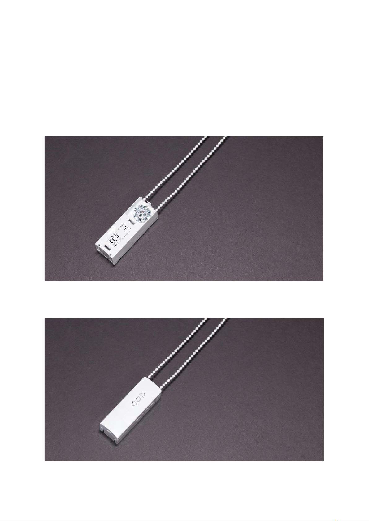
Picture 4-Battery
The release button (picture 4, position 1) is used when detaching the battery pack from the MOVEZ device.
The led indicator (picture 4, position 2) can have the following states:
LED state
Meaning
Stable ON
Charging
Blinking
Error indication
Off
Fully charged or not plugged in
Table 9
The battery pack can be charged with any standard 0.5A USB power adapter source.
Charging starts when a USB power adapter is attached to the battery pack.
It will take about 13 hours to fully charge a battery and because the charger is smart it will automatically turn off
when the battery is fully charged no matter status before charging starts. This means charge time can be less than 13
hours if the battery is not completely empty when charging starts. When the charging is complete the indicator led
will be off.
22 Alternative power source
The alternative power source that can be used is an AC to DC, switch mode power supply with output regulated to
DC 8V 1.3A and a micro USB type B connector. When this is used the battery pack is not needed.
23 Solar panel
The solar panel must always be installed indoors. Insert the cable from the solar panel to the battery device USB
connector (picture 4, position 3).

14
24 Calibration of endpoints
MOVEZ is calibrated with the physical buttons (picture 2, position 1, 2 and 3). Because MOVEZ can be installed in
many ways the buttons up (picture 2, position 1) and down (picture 2, position 3) can make the product on which
MOVEZ is installed on run in different directions depending on installation. After the endpoints are set the buttons at
the device will however be correct and always give correct action.
The two buttons up and down will make the motor either go to up (Open, ON or position 100) endpoint or down
(Close, OFF or position 0) endpoint.
Calibration of “up” (Open, ON or position 100). This is the maximum open position.
Procedure explained below,
1. Push and hold in the stop button (picture 2, position 2).
2. With the stop button pushed in, push and hold in the up button (picture 2, position 1).
3. Let go of both buttons. The led indicator (picture 2, position 5) will then blink slow green to indicate that the
device is in calibration “up” mode. Use the up and down buttons to set the maximum “up” position. The
“up” position is the position when the product on which MOVEZ is installed at DOSE NOT cover the window.
4. When the desired “up” position is found click the stop button. The position will now be saved, and the
blinking will stop.
Calibration of “down” (Close, OFF or position 0). This is the maximum closed position.
Procedure explained below,
1. Push and hold down the stop button (picture 2, position 2).
2. With the stop button pushed in, push and hold in the down button (picture 2, position 3).
3. Let go of both buttons. The led indicator (picture 2, position 5) will then blink rapid green to indicate that the
device is in calibration “down” mode. Use the up and down buttons to set the maximum “down” position.
The “down” position is the position when the product on which MOVEZ is installed at DO cover the window.
4. When the desired “down” position is found click the stop button. The position will now be saved, and the
blinking will stop.

15
25 Installation of the motor and the accessories
Check the condition of MOVEZ upon unpacking it, do not install if damaged.
Check if MOVEZ is compatible with the product you intend to install it on before installing, do not install if it’s not
compatible.
Make sure the product you intend to install MOVEZ on is working correct and don’t have any defects, do not install if
there are any defects.
The motor inside MOVEZ has a torque of about 1Nm and incorrect installation and/or usage can be dangerous.
Make sure that the cord or bead chain of the product you intend to install MOVEZ on is compatible, do not install if it
does not fit.
Before installing MOVEZ make sure that there is enough free space in the window for MOVEZ to operate freely, do
not install if there is a possibility that things can get caught and tangled in by the motor motion.
Only mount MOVEZ according to instructions in this manual.
Warning! - Before starting, carefully read the warnings under section 1. It is important that you install MOVEZ as
described in this manual to ensure safe use of the motor.
16
26 Bead Chain Installation
Important! If the bead chain has a connector make sure that the bead chain connector is running smoothly with
metal pulley.
Many different sizes of bead chain and connectors exist and MOVEZ is designed to fit as many as possible, but
compatibility to make sure MOVEZ fits the product it’s about to be installed on need to be established before
installation.
26.1 Mounting bead chain to pulley
The bead chain needs to be taut enough, so the bead chain doesn’t skip metal pulley.
Picture 5-Bead chain pulley
26.2 Attaching bead chain
Picture 6-Bead chain

17
27 Cord Loop Installation
When installing the cord loop it’s important to make sure the center hole in the spool lines up correctly with the hole
on the motor output axel. The metal pieces that are bent around the cord loop center hole should grip the motor
output axel.
27.1 Mounting cord loop to pulley
The cord needs to be taut enough, so the cord doesn’t slip in the cord loop spool.
Picture 7-Cord loop pulley
27.2 Attaching cord loop
Picture 8-Cord loop
18
28 Plain Cord Installation
Products that are operated by just pulling a cord need some preparation in order for MOVEZ to operate them.
1. Remove all plastic parts from the cord
2. After removing the plastic parts make a knot on the end of the cord
Picture 9-Preparing cord
28.1 Mounting cord to the spool
Picture 10-Attaching to spool
28.2 Attaching cord
Picture 11-Cord spool

19
29 Ways to get correct position for installation
Option 1
Use a template to mark-up the location for the device.
Figure 12-Mounting plate mark-up
Option 2
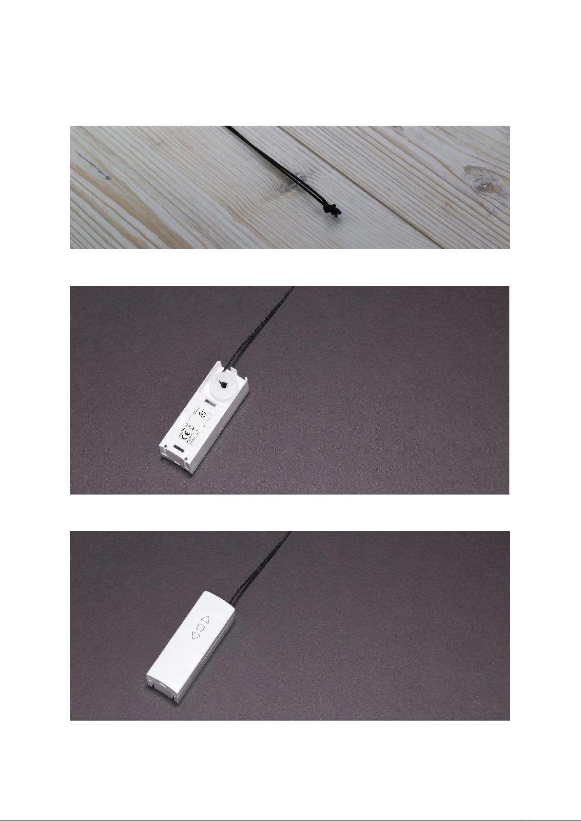
Use the mounting plate to mark-up the location of the device.
Picture 13-Mounting plate
20
The wall mounting plate used to attach the MOVEZ to the wall.
Picture 14- Mounting plate
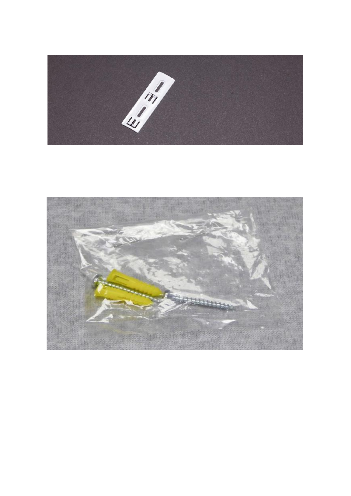
Use screws and anchor to attach mounting plate to wall.
Picture 15- Fastener
Table of contents
Other Teptron Window Blind manuals

Popular Window Blind manuals by other brands


Victoria M
Victoria M SYSTEM VS 1 Original assembly instructions

Draper
Draper FlexShade instructions

Lafayette
Lafayette Classic Collection Echelon installation instructions

LuxaFlex
LuxaFlex LUMINETTE Product information manual

LuxaFlex
LuxaFlex RecessFix Installation

KWANTUM
KWANTUM Vertical Blinds Assembly manual

Draper
Draper FlexShade C MO Series Installation & operation instructions

Isotra
Isotra SD 3 Assembly manual

YewdaleDefiant
YewdaleDefiant C40-60 Manufacturing Instructions

Rollos
Rollos Comfort DF-Rollo Assembly and operating instructions

LuxaFlex
LuxaFlex Super Nova Mounting instruction

MHZ
MHZ 11-8110 Installation and operating instructions