Tequipment M-3850D User manual

AUTO/MANUAL RANGE DUAL-DISPLAY
OIGITAL MULTIMETER
OWNER'S MANUAL
DUAL DISPLAY DIGITAL
MUlTIMEIER
With PC lnlerfoce
M-385OD,/ M-386OD(True rms) /
M-3870D
((A
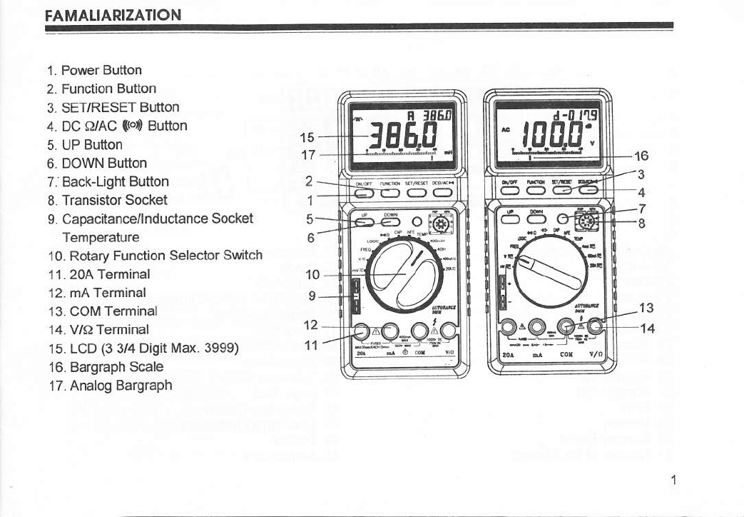
FAMAI.IARIZATION
1. Power Bulton
2. Function Butlon
3, SET/RESET BUttON
4. Dc §rAC td Button
5. UP Button
6. DOWN Button
7. Back-Light Button
8. Transistor Socket
9. Capacitance/lnductance Socket
Temperature
10. Rotary Funclion Selector Swtch
11. 20A Teminal
12. mA Terminal
13. CO[, Terminal
14. V/O Terminal
15. LCD (3 3/4 Digit irax. 3999)
16. Bargraph Scale
17. Analog Bargraph
15
17
2
1
5
6
!
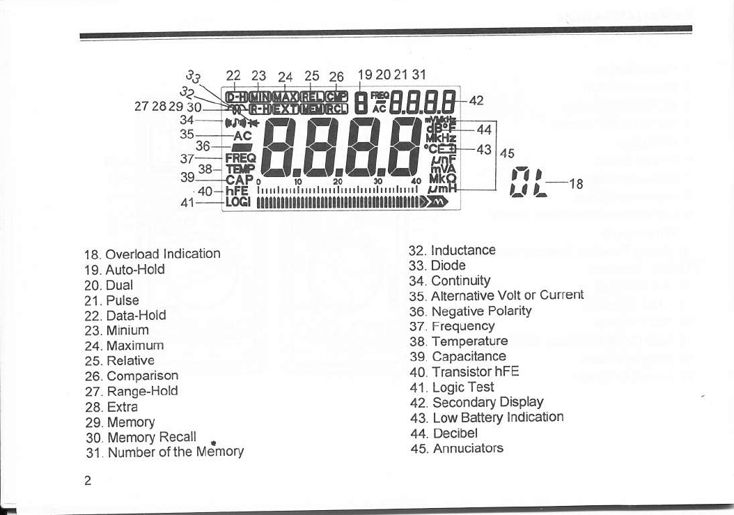
26 19 20 2131
27 2829 30
37
'1 8. Overload lndication
19. Auto-Hold
20. Dual
21. Pulse
22. Data-Hold
23. [4inium
24. I\ra(imum
25. Relative
26. Comparison
27- Rang+Hold
28. Extra
29. Memory
30. Memory Recall .
31. Number ofthe Memory
2
32. lnductance
33. Diode
34. Continuity
35. Altemative Volt or Current
36. Negative Polarity
37. Frequency
38. Temp€rature
39. Capacitance
40. Transistor hFE
41. Logic Test
42. Secondary DisPlaY
43. Low Battery lndication
44. Decibel
45. Annucìators
'ff8.ffi.8
1"',,,,,,f,,,,,"'fr ,,,r,,,t,,,r,,'if
CONTENIS
1 - lnlroduction
6-5. Continuity Testìng ..
6-6. Checkrng Diodes
6-8 Checkng Transistors
6-9. Measunng TemPerature ....... . ........ ' """ '
6-10 checking Signal Oulput.. . . ..... . ........ ' """ "
6-1'1. lnductance test. . .
6-12 Measunng Curaent
32
33
31
36
37
38
38
42
45
15
46
48
48
49
6-13. lJsing lhe Meterwith a Computer........ ' ""
7 Care and Maintenance
7-1. Replacing the Fuse
7-2 GeneralMainlenance
8. Specifications
8-1 General Characteristics .... . .......
8-2. Special Characterislics . . ....... ...... . . .....
Due to our policy to refine the products continuously, this
manual may contain minor differences in specmcation,
components, parts and chcuit deggn of ihe instrument
actually delivered.

l. lntoduclion
W h this Digital multìmeter, you have acqtired a
high-quality, povirerful performance, heavy-duty
rugged and handheld multimeter that will give
you confidence and peace of mind in your every
measuring iob.
Please read these operating instruclions very
carefully. beforc commencing your measure-
2. Sotety Iniomotlon
2-1. Sofety roqullomenl§
This meter has been manufaclured and
testèd in accodance with lEC1010l/
EN6|01G1 Paft'l: Safety Requirement for
Electrical Equipment for measuremeni,
controland laboratory use, Safety Class ll,
Overvoltage category ll.
This manual @nlains information and
warnings which must be observed to as-
sure safe operation and maintaìn th6
meler in safe condition
2-2. Sofely symbols
The following symbols have been placed
on lhe meter to remind you of measure-
menl limitations and safety.
204 The maximum current lhat you
can measure at thi§ terminal is
2oamps DC/AC. This terminal
is fuse protected. l/Vhen using
this lange with high current,
keep the duty cycle to 30 sec-
onds on load, 15 minute§ off
load.
The maximum curreni that you
can measurc with this terminal
is 4mA or 400m4 DC/AC. This
terminal is protecled by a
80omA fuse.

MAX
+ soov
MAX
= r000v
750V
,
To avoid olectric shock or in-
strument damage, do not con-
nect the common lnput
Terminal COM to any source of
more than 500 volts with re-
spect to earth/ground.
The maximum voltage this
meter can measure is '1000v
DC or 750V AC.
Be exceptionally careful when
measuring high voltages. DO
NOT TOUCH THE TERI\4I-
NALS OR PROBE ENDS.
Refer to lhe complete operating
instruc'tions.
lndicates protection clas§ ll,
double insulation.
2-3. Sofety Wqmlngs
2-3-1- To prevent ebcaic shock hazard
and/or damage to the meter, do not
attempt to measurc voltage exceeding
1000V DC or 750V AC.
2-3-2. To avoid damage to the méter and/or
iniury, obseNe the inPut limits as
stated in Table 1.
2-3-3. lo avoid damage to the mèter. dis-
connect test lead§ from test points be_
fore changing the functionfange.
2-3-4. To avoid electric shock, be careful
when working above 60V DC 25V AC.
Such voltage Pose a §hock hazard.
NOT FOR HIGH ENERGY INDUSTRIAL USE,

2-$5. The 20A range is prolected by a fuse.
To avoid damage or injury. use thè
meter only in circuits limits by fuse or
circuits-breaker to 20A or 4000VA. Do
not apply voltage to between 204 or
mA and COM terminals. This warning
is lo assure protection against injury
and/or damage to the meter and the
user.
2-&6. Do not gel lhe meter and test leads
2-3-7. Ensure the test leads are in good con-
diiion
Table 1 INPUT LlirlTS
Worning:Sources like smallhand-held radio lransceivers, fixed stalion radio and lelevision lrah-
smitters, vehicle radio lransmjtlers and cellular phones genèrate electromagneiic radiation that
may induce voltages in the test leads of lhe multimeter In such cases lhe accuracy of the multi-
meter cannot be guaranteed due to physical reasons.
FUNCTION TERMINAL INPUT LIMII
VDC V/E' +COM l OOOV DC
v/o +cotM 750VAC
o t"» V/Q +COM 25OV DC/AC
MA DC/AC mA+COi, 400m4 DC/AC
2OA DC/AC 204+COM 2OA DC/AC
--l<- V/o +CO[/l 250V DC/AC
Freq. v/§, +coM 75OV DC/AC
Loqic V/o +CO[,| 250V DC/AC

3-t. tnstolllng lhe Bqfièry
Your meter rcquires a 9V battery for power.
The Éj symbol appears when the battery
voltage drops to certain limits. For correct opera_
tìon, replace the battery as soon as possible.
Continued use with a low battery will lead to er_
rors in readings,
WARNING : TO AVOID ELECTRIC SHOCK,
DISCONNECI BOTH LEADS FROM ANY
EQUIPI\4ENT BEFORE YOU REMOVE OR IN-
STALL THE BATTERY,
Followthese steps to installthe battery.
1. Turn off the power and disconnect the two
test leads.
2. Remove the screw to open the battery com_
PREPARING FOR OPERATION
--
3. Place ihe battery inside the insulation cap_
sule and snap it onto Place.
WARNING:DO NOT DISCARD THE PRO-
VIDED BATTERY INSULATION CAPSULE, IF
YOU DO NOT USE THIS INSULATION CAP.
SULE PROPERLY, lT ÀIlGHl CAUSE DAI/I-
AGE OR INJURY.
4. Replace the battery compartment cover and
the screw.
WARNING : DO NOT OPERATE THE iTETER
UNTIL YOU REPLACE THE BATTERY AND
CLOSE THE BATTERY COMPARTMENT
COVER,
Zn
Remove the screw to open the battery com-
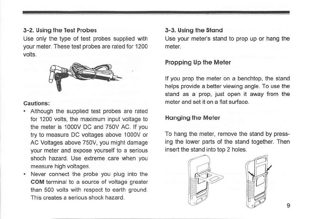
3"2. Using the Iesl Probes
Use only the type of test probes supplaed with
your meter. The§e test probes are rated for '1 200
3-3. Uslng the Slond
Use your meteis stand to prop up or hang the
meter.
Propping Up the Meter
lf you prop ihe meter on a benchtop, the stand
helps provide a better viewìng angle. To use the
stand as a prop, iust open it away from lhe
meter and set iton a ffat surface.
Honglng lhe Mèter
To hang the meter, remove the §tand by press-
ing the lower parts of the stand together. Then
insertthe stand into top 2 holes.
Cauilons:
. Although the supplied test probes are rated
for 1200 volts, the maximum input voltage to
the meter is 1000V DC and 750V AC. lf you
lry to measure DC voltages above 1000V or
AC Voltages above 750V, you might damage
your meter and expose yourself to a serious
shoch hazard. Use extreme c€re when you
measure high voltages.
' Never connect the probe you plug into the
COM terminal to a source of voltage greater
than 500 volts wilh respect lo earth ground.
This creales a sedous shock hazard.
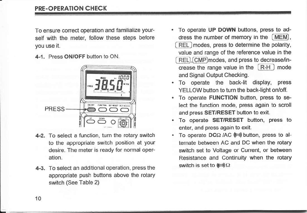
PRE-OPERATION CHECK
To ensure @necl operation and familialize your-
self with the meter, follow these steps before
you use it.
+1. Press ON/OFF button to ON.
PRESS
To select a function, tum the rotary switch
to lhe appropriate switch position at your
desire. The meter is ready for normal oper-
ation.
To select an additional operation, press thè
appropriate push buttons above lhe rotary
switch (See Table 2)
. To operate uP oo\ryN buttons, press to a4
dress the number ot memory in the mEMì,
(-RELlmodes, press to determine the polarity,
value and range ot the reference value an lhe
fREB,@modes, and press to decrease/ln-
qease the range value in the G-H I mode
and Signal Output Checking-
. To operate the back-lit display, press
YELLOW button to tum lhe back-light orvoff
. To operate FUNGTIoN button, pross to sè
lecl the funclion mode, press again to scroll
and press SETIRESET button to exrt.
. To operate SETTRESET button, press to
enter, and press again to exit.
. To operate OCA /AC $oÙ button, press to al-
ternate between AC and DC when the rolary
switch set to Voltage or Current, or betwo€n
Resistance and Continuity when lhe rolary
$rritch is set to tsro
4-2.
43-
10

HOW TO U§E THE METER
This section describes your meter and how to 1. ON/OFF POWER OMFF
use at. Press ON/OFF (RED) butlon to turn the meter
FOR EASY REFERENCE, EACH DESCRIP- on. Press again to lurn the meter off.
TION IS NUMBERED AND KEYED TO THE
ILLUSTRATION INSIDE THE FRONT COVER. Aulomolic Powèr-ÒIf
5-1. Pu§hbulions Automatic Power-off extends the life of the bat-
tery by tuming the meter off if neither the rotary
llems 1 - 7 descnbe how lo use the switch nor a pushbufton is operated for 10 min-
pushbuttons- These butlons are used (in con- utes-
junction wilh rotary swjtch) to select operating However, dudng signal output checking and
modes. Wlen a button is pushed, the beeper communication with a PC, the power witt not be
sounds. A summary of pushbutton operations is turned oIf automatically.
shown an Table 2. An annunciator js displayed to
indicate that a mode or function has been se.
lecled. A quick way to reset all the pushbuttons
lo their default state is to tum the tutary switch
to an adjacent function and then back to the
function you are using.
11
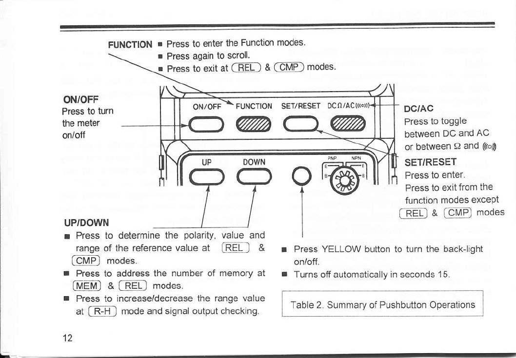
FUNCTIO{ . Press to enter ihe Function modes
0CO/AC«F,
@
FUI'lCTlON
@
ON/OFF
Press to tum
the meter DC/AC
Press to toggle
between DC and AC
or between O and (fÒ»
SET/RESET
Press to enier.
Press io exit from the
funclion modes except
l@ & [et4P] modes
uP/DOWI
. Press to determìne the polarity, value and
range of the reference value at @J &
l-e t\48ì modes.
a Press to address the number of memory at
(trrletrrt'ì & [neD moues.
r Press to increase/decrease the range value
at l-FH I mode and signal oulput checking.
12
Press YELLOW bulton to tum the back-light
Turns off automatically in seconds 15
. Press agah to scroll
. Prèss to exit at (TiEfl & (eMFl modes.
o
1
Table 2. Summary of Pushbuuon Operations
oowN

2. Functlon
When you first on the meter, A (auto hold), d
(dual) or P (pulse) indicalor will be displayed at
the front of secondary display depending on the
measuring ranges selected. Each press of the
FUNCTION button, your meter will enter the ad-
vanced functions.
Sequence ofscroll in FUNCTION modes.
ljM=t@-@,fc@
f RH_l-rfan-{M-Efril.-fÉm
3 SET/RESET
You can select or deselect the functions by
pressing SET/RESET button.
ln the function modes of [$Q and @ ,
the RESET function does not work.
To exit from these modes, you have to move the
function selector to an adjacent range or press
FUNCTION key.
4 DCO/AC ffo'
Press DCA /AC (ol button lo toggle between AC
and DC when the rotary switch is set to Voltage
or Current, or between Resistance and Continu-
itywhen the rotary swilch is set to to, O.
5, & 6, UP/DOWN
Press UP or OOWN buttons to determine the
polarity, value, and range ofthe reference value
in IRELI and fEMÈl modes, to address the
numberof memory in @a[nctl modes,
and lo increase/decrease lhe range value rn
(-nFl mode and signal output checking.
7. Back-Lit Display
Press Yellow button to turn the Back-light orvorf.
Back-lit display can be used in poor light condi-
tions. Back]ight tums ofi automalically after 15
seconds to extend battery life.
13
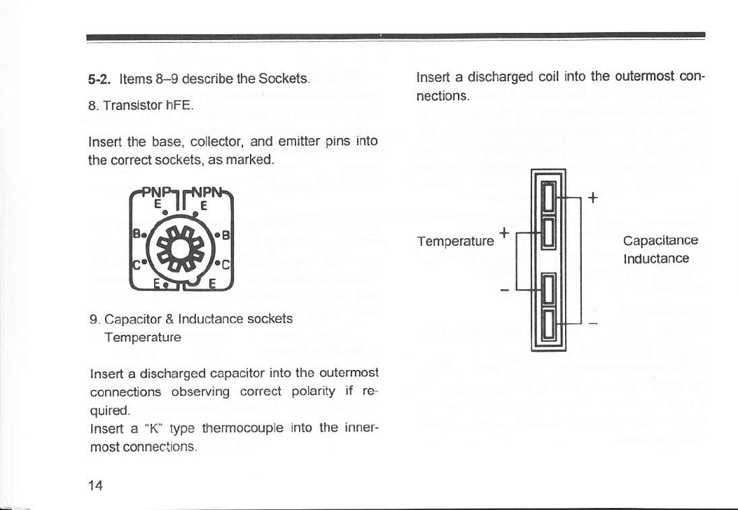
5-2. ltems 8-g describe the Sockets.
8. Transistor hFE.
lnsert the base, colleclor, and emitter pins into
the correct sockets, as marked.
g. Capacitor & lnductance sockets
Temperaturc
lnsert a discha.ged capacitor into the outermost
connections observìng conect polarity if re-
quhed.
lnsed a "K' type themocouple into the inneG
most connections.
14
lnsert a discharged coil into the outormo§ con-
neclions.
Temperature +Capacitance
lnductance
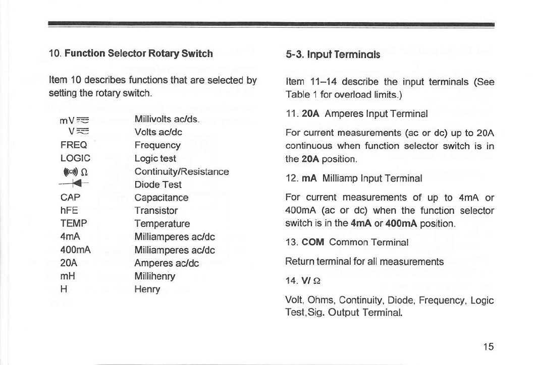
10. Functlon Selector Rotary Swltch 5-3. lnputTèrminol§
Item '10 descdbes functions that are selected by [em 11-14 desciibe the input terminats (See
setting iho rotary switch. Table 1 icr ovedoad limits.)
mv= Millivolts aclds. 11'204 Amperes lnputTerminal
V = Volts acldc For current measurements (ac or dc) up to 2OA
FREQ Frequency continuous when funclion selector switch is in
LOGIC Logictest the 204 position.
F, O Continuity/Resistance
-'i' Diode Te;t 12 mA ['lilliamp lnputTeminal
CAP Capacitance For current measurements of up to 4mA or
hFE lransislor 400m4 (ac or dc) when the function selector
TEMP lemperature switch as in the 4mA or 400mA position.
,{mA Milliamperes acldc 13. coM common Terminat
400m4 l\rilliamperes acJdc
20^ AmpeÈs acJdc Return terminal for all measurements
mH Millihenry M.VI A
H Henry Volt, Ohms, Continuity, Diode, Frequency, Logic
Test,Sig. Outpul Terminal.
15

5"4. Digltol ond Bor Groph Dl§ploy§
Items 1$-18 describe the digital and bar graph
displays.
15. DigitalDasplay
Digital readings are displayed on a 4000-count
display with automatic polarity indication and
decimal poìnt plaoement.
16. llllllllllllllllllllllllllllllltll»lD Analog Bar Graph
The bar graph consists of 43 segments that
illuminate from left to right as the input increase.
It functions much the same as the needle on an
analog meter wilhout the mechanical overshoot
inherent in needle movements-
lf the inplt equals or exceeds 4,000 counts on
lhe range selected. OL is drsplayed with flashing
the bar-graPh and beeping.
17. i,,,,,,,,,f,,,,,,,,iiÌ,,,,,,,fi,,,,,,,ii Bar Graph scare
Scale for absolute readings.
18. OL overload lndication
OL is displayed with flashing the bar-graph and
beeping when input is too excessive to display.
,1r
UL
A
nr
UL

5-5. Using lhe Advonced Funclìons 20. P Pulse
For AC Cunent measurements, A or P is dis-
Item 19-31 descdbe the advanced functions. phyed at thè front of secondary display. lÀen p
19. A Auto Hold is turned on, it indicates that the input value has
a frequency while shows the reading taken by
auto-hold mode on the secondary display. lf you
set the meter at (_EXlì mode, your meter can
directly display the frequency on the secondary
display.
For the measurements of DC Voltage, Current,
Oiode. Capacitance, hFE and lnductance, A is
displayed at the front ofsecondary display.
' When lhis feature is turned on, the secondary
display shows the reading taken 4-5 seconds
earlier.
EB ]EI'
lAE.E P la50
-,J,*E*50.^
17

21. d DualDisplay
For lhe measurcments of AC Voltages, Fre. readout two diffemet types of measurement at
quency, Temperature and Logic, d is displayed the same time. The meter displays the following
at the front of secondary display to measure and dual measurements;
d -0 ltg
-. [800" d ra00
Hr
l,*'-i*r,"ili-t,ìi-r,.il
I
lnout Ranoe Seleaiion Main Disolav Secondary Display
AC Voltaoe dB(m)
FrceuencY Ac Voltaqe
TemDerafure .C
Logic HI/LO DC Vollaoe
18
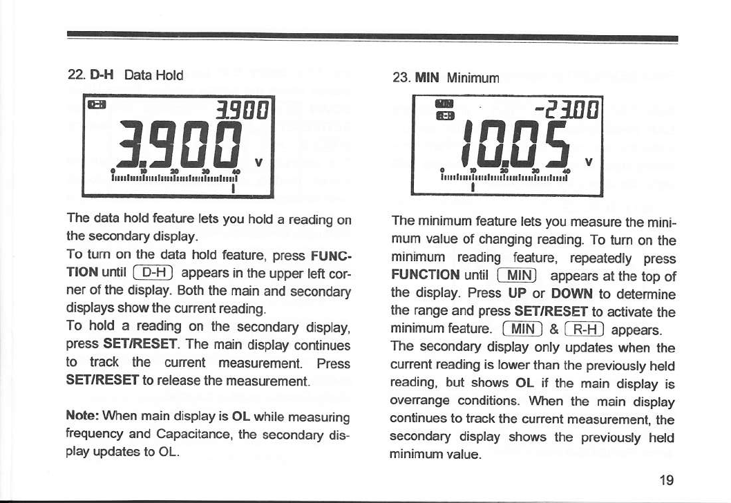
22. D-H Data Hold
ET EO
19Ufi
i -r,"lli-r,"iiì-.'ii-.,11
I
The data hold foafure lets you hold a reading on
the secondary display.
To lum on the data hold feature, press FU C-
llON unt f D+il aprrea6 in the upper tefl cor-
ner of lhe display. Eloth lhe main aM secondary
displays show the cunenl reading.
To hold a reading on the secondary display,
press SETTRESET. The main display continues
to track the curent measuremenl. Prèss
SETTRESET to release the measuÉment.
Nob: Wlen main display is OL tyhile measuring
fiEquency and Capacitance, the secondary dis-
play updates io OL.
23. ll Minimum
The minimum feature lets you measure the mini-
mum value of changing reading. To tum on É|e
minimum reading feature, repeatedly press
FUIICTION until fTi ì appears atthe top of
the display. Press UP or OOWN lo determine
lhe range and press SETTRESET to aclivate the
minimum fearure. @[ a @ appears.
The secondary display onty updates when the
cunent reading is lo!fler than the previously held
reading, but shows OL if the main display is
overange condilions. \ivhen the main disptay
conlinues to hack the cunent measurèment, the
secondary display shows the previously hetd
minimum valuè
E -?:nE
,l8,q5.
I
19
This manual suits for next models
2
Table of contents


