Teradyne Neptune User manual
Neptune Operator Manual
Version 1.1, March 8, 2011

Operator Manual /
Teradyne Confidential - i -
Table of Contents
1 Safety Information 1
1.1 Safety Standards Compliance 1
1.1.1 EMI/EMC 1
1.2 General Safety Guidelines 1
1.3 Use of Genie Lift for System Maintenance 2
1.4 Safety and Product Labels and Symbols 2
1.4.1 Product and Safety Compliance Labels 4
1.5 Warnings and Cautions 7
1.5.1 General Warnings and Cautions 7
1.5.2 Physical Warnings and Cautions 8
1.5.3 Electrical Warnings and Cautions 9
1.5.4 Chemical Warnings and Cautions 10
1.6 Electrostatic Discharge Guidelines 11
1.6.1 Wrist Strap and Ground Clip 11
1.6.2 Static-Producing Materials 12
1.6.3 Hardware Handling and Shipping 13
1.6.4 Humidity in the Work Area 13
1.6.5 Optional Equipment to Avoid Static 13
1.7 Types of ESD Equipment Failures 14
1.7.1 Catastrophic Failure 14
1.7.2 Soft Failure 14
2 Entering and Exiting the System 15
2.1 Safely Stopping Automation 15
2.2 Entering the System 15
2.3 Exiting the System and Restarting Automation 17
3 Check or Reset Host and System PC 19
4 Misaligned Drives on the Conveyor Events 22
5 Exception Drawer Events 23
6 Sled Garage Replenishment 26
7 Verifying Compressed Air Pressure 27
8 System Power Down/Up 29
8.1 Powering the System Down 29
8.2 Powering the System Up 30
8.3 Unexpected System Power Down 30
9 Clean/Inspect the Atrium 32
10 Appendix A - Terms, Acronyms and Abbreviations 33
Operator Manual /
Teradyne Confidential - ii -
Operator Manual Revision History
Date: March 8, 2011
Section Page Comments
Safety Information 1Added new Safety Information
section.
System Power Up Down 29 Added new UnexpectedSystem
Power Down sub-section.
Acronyms and Abbreviations 33 Added new Appendix for Acro-
nyms and Abbreviations.

Operator Manual / 1 Safety Information
Teradyne Confidential - 1 -
1 Safety Information
1.1 Safety Standards Compliance
With isolation of the Neptune chamber power, the system has built-in fail-safe
operations that are compliant with:
lEmergency Machine Off (EMO)
lCircuit breaker protection
lPhase Fault Detection
All hazardous voltages are covered and warning labels attached per international
standards and circuit breaker 30A meets factory main DB requirements.
The Neptune system, as designed, has an IP2X degree of protection to IEC 60529.
Regarding robot safety compliance and guidelines: the KUKA documentation
includes extensive safety information. Operator, service and maintenance
personnel should read the KUKA KR 16 L6-2 safety instructions before operating
the robot.
1.1.1 EMI/EMC
The Neptune system complies with the EMC Directive 2004/108/EC and the
following EMC/EMI standards:
lEN61326-1:2005
lEN55011 Radiated and Conducted Emissions
lEN6100-6-2 Immunity
lEN61000-4-2:2001 Electrostatic Discharge
lEN61000-4-3:2002 Radiated Fields
lEN61000-4-4:2004 EFT/Burst
lEN61000-4-5:2001 Surge
lEN61000-4-6:2003 RF Coupled Fields
1.2 General Safety Guidelines
To prevent serious accidents to yourself against shock, static, or heavy objects, and
against damage to any hardware, review the guidelines provided in the following
sections. These guidelines are suggested by Teradyne and do not override the
safety procedures that apply to your site. Follow the internal guidelines, policies,
and procedures that are documented and supported within your organization.

Operator Manual / 1 Safety Information
Teradyne Confidential - 2 -
Topics include:
lSafety and Product Labels and Symbols
lWarnings and Cautions
lElectrostatic Discharge Guidelines
lTypes of ESD Equipment Failure
1.3 Use of Genie Lift for System Maintenance
A GL8 Genie Lift, equipped with ladder and lifting tray, is provided for use in
maintaining the system. Field service personnel will be required to use the lift to
service all system components that cannot be safely managed at floor level.
To operate the lift safely, field service personnel are referred to the Genie
Operator’s Manual, Genie Lift (Part # 35566).
Seagate site procedures for working at elevated heights must be followed. Prior to
performing work, contact the facility manager for clarification of procedures.
1.4 Safety and Product Labels and Symbols
The information provided in this section is not product specific and, therefore, all
labels might not appear on your hardware.
Carefully review the safety symbols, Electrostatic Discharge (ESD) symbols and
labels that appear on hardware.
These labels and symbols are derived from International Electro-technical
Commission (IEC) 417 and from Occupational Safety and Hazard Administration
(OSHA) 29 CFR 1920, or ANSI Z535, or a combination thereof.
Safety labels and symbols can include one or more of the following. This is not a
complete listing; your hardware can contain other labels that do not appear here.
Table 1-1: Safety Labels
Symbol Description
IEC yellow CAUTION label. Iden-
tifies a specific area of hardware that
has important servicing operating
requirements described in the accom-
panying documentation

Operator Manual / 1 Safety Information
Teradyne Confidential - 3 -
Symbol Description
HEAVY OBJECT label. Cautions
that there is a heavy object that can
cause injury if proper lifting pro-
cedures are not used when removing
or replacing it.
ANTISTATIC label. Indicates that
special antistatic or preventive meas-
ures must be taken to avoid hard-
ware damage or equipment
malfunction.
Safety symbols can include one or more of the symbols as shown in the following
table.
Table 1-2: Additional Safety Symbols
Symbol Description
HIGH-VOLTAGE FLASH. Defines a con-
nection where a dangerously high volt-
age, above 60 V, either AC or DC, may
be present. (Black signifies 60-999 V; red,
1000 V or more.)
CIRCUIT GROUND. Identifies a con-
nection point where instrumentation is ref-
erenced to ground. Instrumentation
grounds include: protective, chassis,
radio frequency, signal, and so on. Typ-
ically, this symbol is near coaxial con-
nections.
WARNING, RISK OF ELECTRIC
SHOCK. Indicates presence of dan-
gerous voltages and risk of electric shock.
Operator Manual / 1 Safety Information
Teradyne Confidential - 4 -
1.4.1 Product and Safety Compliance Labels
Product and safety compliance labels may include one or more of the following:
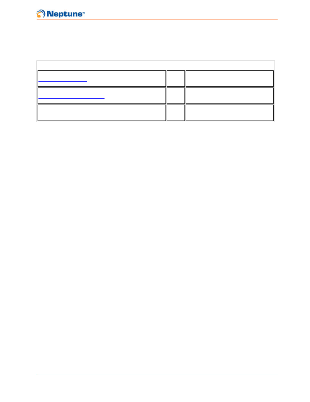
Table 1-3: Safety Compliance Labels
Label Comments
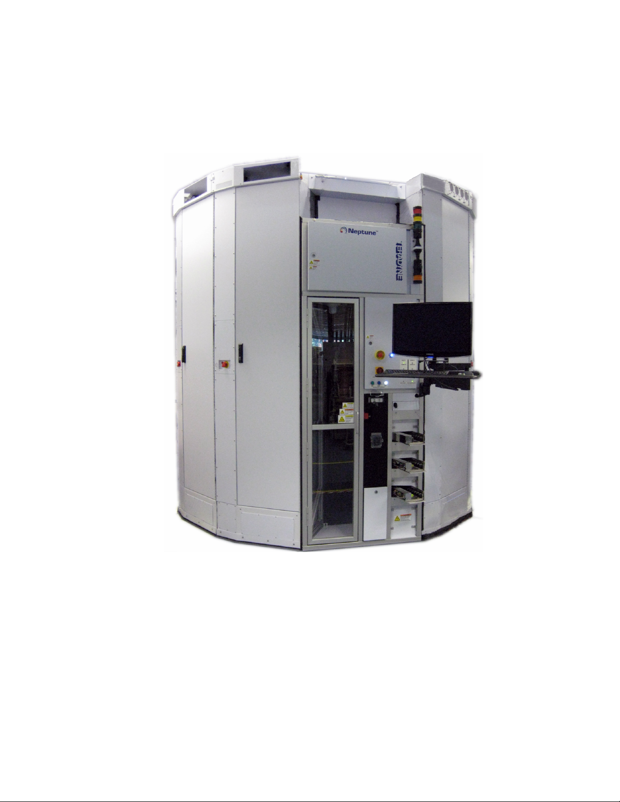
Neptune 2 product label (conveyer load-
ing system). Located on feeder and racks.
TUV Rheinland - T Mark
TUV Rheinland - NRTLMark
TUV Rheinland - SEMI S2 Mark

Operator Manual / 1 Safety Information
Teradyne Confidential - 5 -
Label Comments
TUV Rheinland - TUV ID Label
PROTECTIVE GROUND. Indicates the
entrance point of the safety ground wire of
the AC main input. Located next to safety
ground studs in the feeder and racks.
EARTH (GROUND) TERMINAL. Indi-
cates a conductive point that is ref-
erenced to the safety ground wire of the
alternating current (AC) main input, but
that is not part of the AC service wiring.
Located next to each earth ground ter-
minal in the feeder and racks.
CHASSIS GROUND. Identifies where a
wire is connected to a chassis point for
ground reference or other function, such
as static discharge. Located at each chas-
sis ground stud in the feeder and rack.
FUSE REPLACEMENT. Indicates that a
fuse must be replaced by one of the same
type and rating to ensure safe and proper
operation. Located on feeder high voltage
box.
HAND CRUSH LABEL near tote drawer.
Apply to manual feeder.
Operator Manual / 1 Safety Information
Teradyne Confidential - 6 -
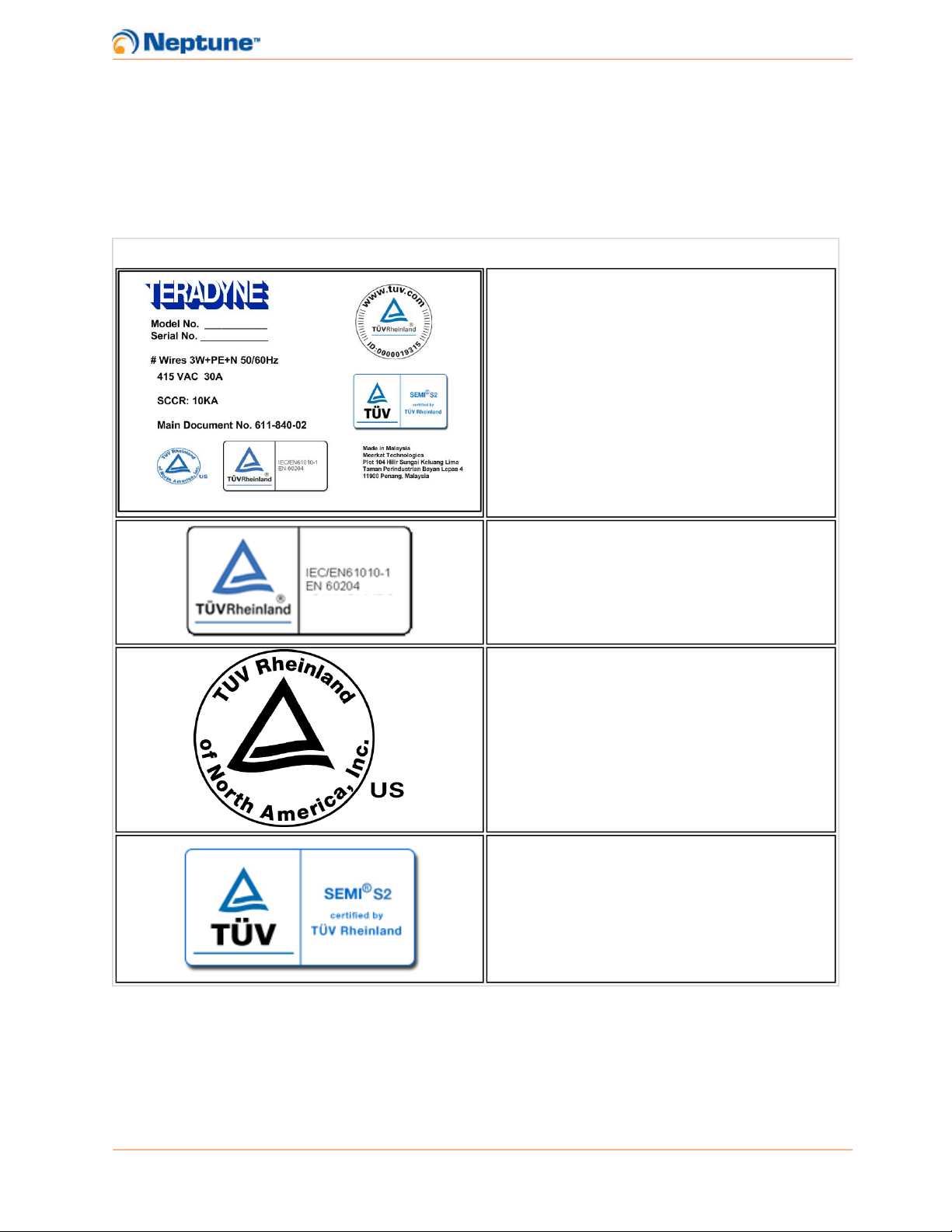
Label Comments
Use lockout tag out before servicing sys-
tem. Located on feeder NEMA box.
Lock out compressed air source and
bleed off pressure before servicing.
Located on feeder NEMA box.
Do not step or stand on labeled surface.
Located on top canopy.
WARNING, RISK OF ELECTRIC
SHOCK. Indicates presence of dan-
gerous voltages and risk of electric
shock.Disconnect power before servicing.
Located on feeder and all racks.
Live voltages present after EMO acti-
vation. Located on feeder NEMA box.
Electric and pneumatic power sources
present. Disconnect services before serv-
icing. Located on feeder NEMA box.
Uninterruptible Power Supply (UPS) volt-
age present when power is off. Located
on feeder NEMA box.
Operator Manual / 1 Safety Information
Teradyne Confidential - 7 -
Label Comments
UPS supply output. Located near ends of
UPS supply outputs.
1.5 Warnings and Cautions
The following are listings of warnings and cautions associated with the use of the
Neptune system. Specific warnings and cautions are repeated in every procedure
to which they apply. The categories are:
lGeneral
lPhysical
lElectrical
lChemical
1.5.1 General Warnings and Cautions
Table 1-4: General Warnings and Cautions
Symbol Description
Procedures performed by unqualified per-
sonnel represent a serious health hazard
that could result in serious injury and/or
damage to the equipment. Maintenance
must be performed by qualified per-
sonnel, trained by Teradyne.
Safety shoes and safety glasses must be
worn by all personnel involved in assem-
bling and moving the system.
Do not use toxic or dangerous sub-
stances for cleaning the Neptune system
equipment. If specific cleaning instruc-
tions are not presented, use the mildest
method (e.g. small quantity of detergent
and water on external cabinets)
Operator Manual / 1 Safety Information
Teradyne Confidential - 8 -
Symbol Description
Adherence to the recommended schedule
of maintenance is not a reason to post-
pone maintenance if the system’s per-
formance degrades. Take the appropriate
steps to check and resolve any per-
formance problems immediately.
1.5.2 Physical Warnings and Cautions
Figure 1-1: Physical Warnings and Cautions
Symbol Description
Tip over hazard. Do not move this equip-
ment without mechanical assistance.
Crush hazard moving and uncrating
equipment. Safety shoes and safety
glasses are worn by all personnel
involved in assembling and moving the
system.
Uncrating components may expose sharp
objects.
Safeguard your hands and fingers while
handling any fixture or other accessory.
Be sure it is securely supported if you
reach under it. If it is heavy, you must
have another person help to move it.
Possible airborne particles and pro-
jectiles when drilling into floor. Wear
approved eye protection or safety
glasses.
Pressurized device. Possible airborne par-
ticles and projectiles. Wear approved eye
protection or safety glasses.
Operator Manual / 1 Safety Information
Teradyne Confidential - 9 -
Symbol Description
Interlocks to enclosure doors and access
ports should never be bypassed except in
the performance of servicing and only by
trained personnel. Any interlock overrides
must be removed immediately upon com-
pletion of the service task.
DO NOT attempt to make adjustments to
the safety interlocks as they are critical
safety features. Improper adjustment can
cause potential harm to personnel and
damage to critical components.
Protect the floor by and route to the instal-
lation site by placing down floor mats.
1.5.3 Electrical Warnings and Cautions
Table 1-5: Electrical Warnings and Cautions
Symbol Description
When operating high-voltage or high-
power systems:
lHave an assistant present or notify
someone nearby before and after
completing the work.
lRemove conductive items and jew-
elry before installing an instru-
ment, or other hardware, and
operating the test system.
Learn the areas containing high voltage
in each piece of equipment. Do not con-
tact high voltage connections when install-
ing or operating this equipment.
Operator Manual / 1 Safety Information
Teradyne Confidential - 10 -
Symbol Description
Use caution when near the following elec-
trical hazards:
lDirect current voltages greater
than 30 volts (V) root-mean-square
(42 V peak)
lPulses greater than 24 V
lPower combination greater than
240 volt-ampere
lReactive energy greater than 10 J
High-current (greater than 10 A)
system power supplies.
High voltage is present in the AC vaults
(certain sections of the wedges) of the
Neptune system. Serious injury or death
may result if personnel fail to observe
safety precautions.
Before performing any electrical task, lock-
out/tagout procedures should be used to
ensure safety. All procedures must be per-
formed by qualified personnel.
Before performing any AC vault main-
tenance task, turn power OFF at the
supply circuit breaker, and ground points
of high voltage potential before touching
them, to avoid the risk of electrocution.
Static-sensitive devices are present. Fol-
low the approved ESD handling pro-
cedures while working with static
sensitive components.
1.5.4 Chemical Warnings and Cautions
Table 1-6: Chemical Warnings and Cautions
Symbol Description
Contact with epoxy may cause skin irri-
tation. Use gloves when handling glue
gun and epoxy containers.
Operator Manual / 1 Safety Information
Teradyne Confidential - 11 -
Symbol Description
Do not use toxic or dangerous sub-
stances for cleaning the Neptune system
equipment. If specific cleaning instruc-
tions are not presented, use the mildest
method (e.g. small quantity of detergent
and water on external cabinets)
1.6 Electrostatic Discharge Guidelines
The discharge of static electricity, sometimes as a visible spark, is called
electrostatic discharge (ESD). Static potentials can be in excess of several
thousand volts. Many semiconductors, such as metal-oxide semiconductor field-
effect transistors (MOSFET), have terminals that can easily be damaged by static
potentials as low as 20 volts. For this reason, all ESD-sensitive hardware must be
transported and maintained in areas free of electrostatic charges.
To help ensure safe handling of hardware from electrostatic discharge (ESD),
review the following guidelines:
lWrist Strap and Ground Clip
lStatic-Producing Materials
lHardware Handling and Shipping
lHumidity in the Work Area
lOptional Equipment to Avoid Static
1.6.1 Wrist Strap and Ground Clip
Wrist straps consist of conductive straps worn around the wrist and conductive
cords that connect the straps to electrical or earth ground. When used properly, the
wrist straps discharge the static charge on your body to ground, or bring your body
to the same static potential as that of work surfaces, or both. You should also:
lWear a grounded wrist strap before you touch any ESD-sensitive hardware (for
example, component, assembly, or instrument). The strap should fit snugly
around your wrist and contact your skin. If the strap is too loose, it will not provide
sufficient ESD protection.
Note: Do not wear the wrist strap over clothing, as this will prevent the strap from
discharging static charges.

Operator Manual / 1 Safety Information
Teradyne Confidential - 12 -
lExamine or test the wrist strap daily for conductivity and correct fit.
lAttach a ground clip to ESD-sensitive hardware before you remove it from an
anti-static box or static-shielding bag.
lRemove the ground clip from ESD-sensitive hardware after you put it in an anti-
static box or static-shielding bag.
lInspect conductive and grounded work surfaces
lWork surfaces consist of the tabletops and the floor of the work area.
Check for the following:
oWork surfaces that are constructed from a conductive material, like
metal, or that have conductive mats or carpets on the tabletops and
floors.
oConductive cords that connect the work surfaces to electrical or
earth ground.
oResistors used in each grounding cord to keep ESD currents at
safe levels.
oFloor mats that are not worn.
oFloor mats using the correct connections and conductivity.
oTabletops using the correct connections and conductivity.
oYou should also make periodic checks of the work area to deter-
mine the effectiveness of ESD suppression methods and materials.
1.6.2 Static-Producing Materials
Move static-producing materials and tools away from ESD-sensitive hardware. This
material includes but is not limited to:
lPlastic and foam coffee cups
lFood containers and wrappers
lClothing and shoes containing man-made materials
lRubber-soled shoes
lCellophane or paper tape
lAvoid or minimize the following activities:
oAny action that can generate static charge, including putting on and taking
off smocks, wiping feet, rubbing hands, and any similar activities.
oUnnecessary sliding movements, such as dumping devices out of bags,
rapidly sliding ESD-sensitive hardware across a tabletop, and so on.
oUse of adhesive tape. Labels and inspection arrows and dots are per-
mitted (peel slowly from backings to reduce the chance of static buildup).
oContact between paper and ESD-sensitive hardware. Do not enclose
paper in the same ESD container holding the hardware. Enclose doc-
umentation in its own static shielding bag when storing or transporting the
hardware.
oContact between your clothing or hair and electrical devices.

Operator Manual / 1 Safety Information
Teradyne Confidential - 13 -
1.6.3 Hardware Handling and Shipping
When handling ESD-sensitive hardware:
lHandle one piece of hardware at a time.
lAssume all unidentified hardware is ESD-sensitive.
lObey the warnings and safety labels on ESD-sensitive hardware and their con-
tainers.
lUse the correct extraction tools for hardware, if applicable.
lKeep an anti-static box and static-shielding bag closed until you insert or remove
hardware.
lPut anti-static boxes or static-shielding bags on a grounded surface before you
open them.
lAvoid unnecessary touching of leads on assemblies. Where possible, hold
printed circuit boards by the edges and avoid touching the contact fingers, pins,
or connectors.
lWhen moving and storing ESD-sensitive hardware:
oPut an unprotected assembly (or other hardware), after removal from the
system, on an ESD-safe table or in an anti-static box or static-shielding
bag.
oPut only one piece of hardware into an anti-static box or static-shielding
bag before putting them in a shipping box. The shipping box may not have
ESD protection.
oStore full anti-static boxes or static-shielding bags closed, in a horizontal
position, and in an ESD-safe location (grounded cart or table mat).
1.6.4 Humidity in the Work Area
A relative humidity of at least 40-50% is required in all Neptune work areas. Less
than 40% humidity increases the generation of static electricity, making ESD
protection more difficult to accomplish.
1.6.5 Optional Equipment to Avoid Static
The following optional equipment can improve ESD protection:
lClothing designed for ESD protection, including long-sleeved smocks
lTopical anti-static spray or treatment that can be applied to floors, carpets, walls,
ceilings, chairs, clothing, system parts, trays, tools, paper, plastic, and other mate-
rials
lConductive or anti-static chair or stool covers
lConductive shoes or shoe straps
lAir ionizers

Operator Manual / 1 Safety Information
Teradyne Confidential - 14 -
1.7 Types of ESD Equipment Failures
Electrostatic Discharge (ESD) can damage sensitive hardware such as
semiconductor devices, transistors and integrated circuits, which can cause two
types of equipment failures.
1.7.1 Catastrophic Failure
If there is a catastrophic failure, ESD can damage the hardware and make it
inoperative. Catastrophic failures can be identified during troubleshooting due to
damage or loss of functionality.
1.7.2 Soft Failure
If there is a soft failure, ESD can cause increased stress on the hardware without
destroying it. Soft failures will reduce the operating life of the hardware, and can
cause intermittent operation or sporadic malfunctions with no obvious cause.
An accumulation of soft failures can also cause a catastrophic failure. Soft failures
can be difficult to identify and repair because the equipment can continue to
operate correctly most of the time.

Operator Manual / 2 Entering and Exiting the System
Teradyne Confidential - 15 -
2 Entering and Exiting the System
2.1 Safely Stopping Automation
To safely stop automation when the system is running in production mode, the
white STOPbutton must always be pressed first. This must also be done prior to
opening any rack doors because opening a rack door trips the operator safety gate.
Figure 2-1: Stop Button
2.2 Entering the System
1. Once the STOP button has been pressed, the system will unlock the service
access door for approximately one second. During this time, if the operator
needs to enter the atrium, the door can be opened. If the door is not opened dur-
ing this time period, the door will be re-locked for safety purposes. If the door
needs to be opened after it has re-locked, the STOP button can be pressed
again to unlock the door for another short duration. Once the door has opened, it
will remain unlocked.
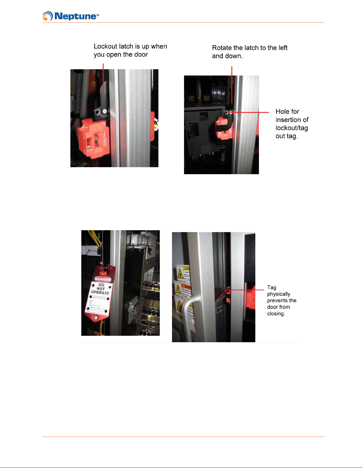
2. Open the service access door and flip down the lockout/tagout latch.
Operator Manual / 2 Entering and Exiting the System
Teradyne Confidential - 16 -
Figure 2-2: Lockout Latch Location
3. Attach the lockout/tagout tag and secure with lock. This will prevent the door
from closing and automation from being restarted while servicing the system.
The robot will remain in safe mode while the system is locked out.
Figure 2-3: Lockout/Tagout Tag in Use
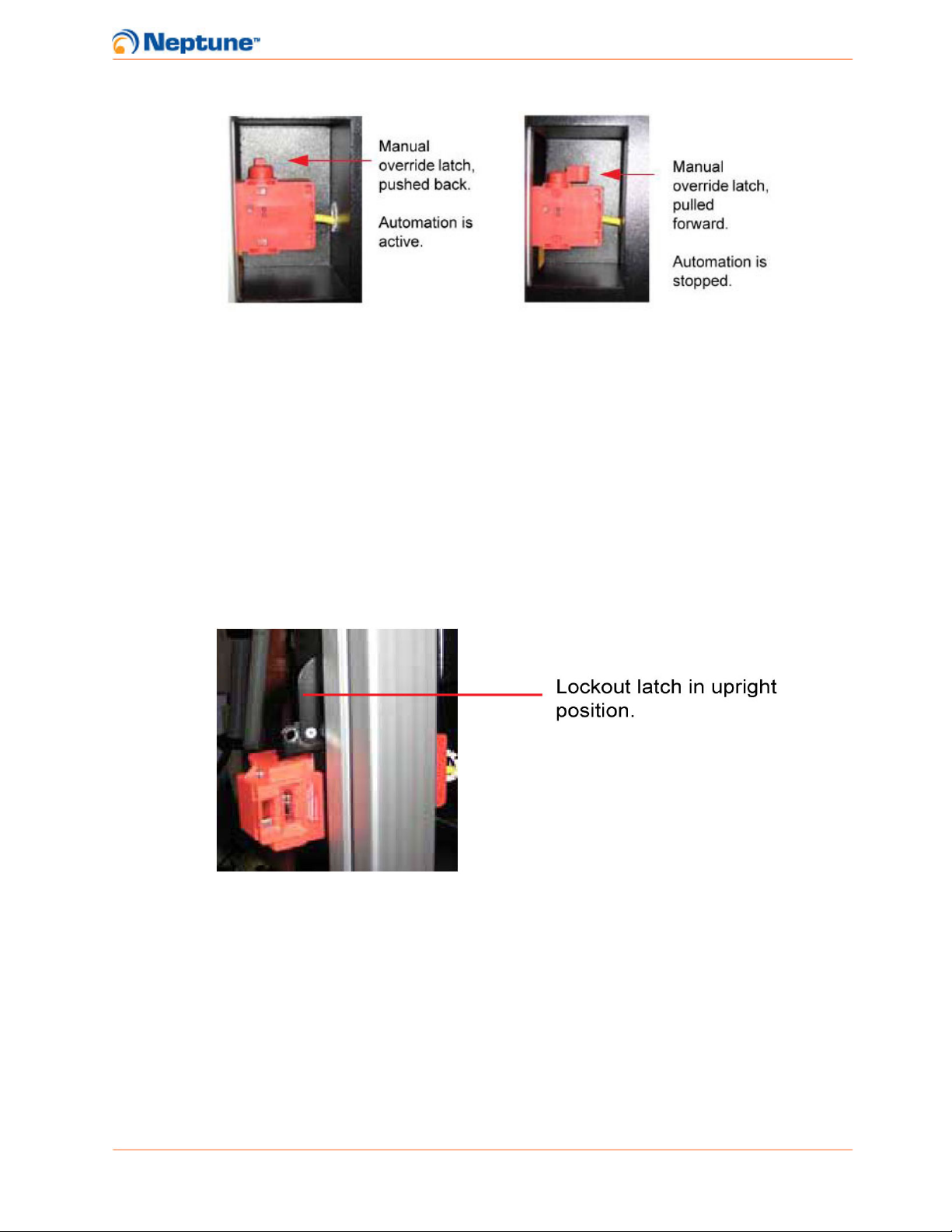
4. If the door locks while an operator is inside of the system, the door can be man-
ually unlocked by flipping the override switch.
Note: It is not necessary to flip this switch when entering the system under normal
circumstances.
Operator Manual / 2 Entering and Exiting the System
Teradyne Confidential - 17 -
Figure 2-4: Manual Override Latch Positions
2.3 Exiting the System and Restarting Automation
1. Once the servicing tasks have been completed, inspect the atrium for tools,
parts or other materials that may have been left behind. Verify that all materials
have been cleaned up and the atrium has been restored to its operating state.
2. If the robot was moved during service, verify that the End-of-Arm Tool (EOAT) is
in a safe position to restart automation. The EOAT should be facing either one
of the racks or feeder approximately one foot from its face. The KUKA Control
Panel (KCP) should also be placed back into automatic external mode.
3. Remove the lockout/tagout tag and flip the latch into the up position.
Figure 2-5: Lockout Latch in Upright Position
4. Firmly close the door and verify that the manual override latch is in the locked
position.
Table of contents
Other Teradyne Test Equipment manuals


