Vlano 100 AV User manual

100 AV
DE AXIAL FAN
User guide
www.vlano.de

DE ! WARNING
Disconnect the fan from the power supply before all connection, adjustment, service and repair work.
Service and maintenance work is only permitted by qualified personnel who have a valid license for
electrical work on electrical systems up to 1000 V.
The single-phase power supply to which the device is connected must comply with the applicable electrical
standards.
The cabling system must have a safety power switch.
The electrical connection is made through a QF mains circuit breaker, which is integrated in the stationary
line. The contact distance at all poles must be at least 3 mm.
Before installing the fan, check that there are no visible defects in the impeller, the housing and the grille
and that there are no foreign bodies in the flow part of the housing that could damage the impeller blades.
Improper use, unauthorized changes, modifications and reworking of the fan are not permitted.
Improper use, unauthorized changes, modifications and reworking of the fan are not permitted.
The device must not be used by children or persons with limited physical, sensory or mental capabilities.
The device is not intended for use by persons with insufficient experience or specialist knowledge, unless
they are under control or have been instructed by a person responsible for their safety.
Children must be supervised and are not allowed to play with the device.
Take measures to ensure that smoke, carbon oxide gases and other flammable substances cannot enter
the room through open smoke outlets or other fire protection devices.
In order to avoid a back pressure and to ensure proper combustion of exhaust gases and gases through
the chimney, ensure that there is an adequate supply of air. The conveying medium must not contain
any dust or explosive or flammable substances,
Contain vapors and other solid foreign matter, sticky substances, fibers and other harmful substances. The
fan is not designed for use in a flammable, potentially explosive environment. Do not close or cover the
suction opening and the outlet opening of the fan in order to ensure optimal air passage. Please do not sit
on the fan or leave anything on the device.
Fulfill the requirements in order to ensure a long service life for the device.
At the end of its service life, the device must be disposed of separately.
Do not dispose of the device with unsorted municipal waste.
2

DE
DESCRIPTION OF LABELS
XXXXXX
Outlet nozzle diameter, mm -
100, 125, 150
Fan series -
AV
Extra options:
_ - Default
T - overrun switch
TH - humidity sensor and overrun switch
Modifications of the motor and the impeller:
Example of the description of the designation:
100 AV T - fans with the outlet nozzle diameter 100 AV series, equipped with an overrun switch.
3

Read these operating instructions carefully before installing and commissioning the device. Compliance with the operating
regulations ensures safe operation of the fan during the entire service life. Keep these operating instructions as long as you
operate the device, as the operating instructions contain the maintenance instructions for the device.
DE
SCOPE OF DELIVERY
The scope of delivery includes:
1st fan - 1 pc;
2. Screws and dowels - 4 pieces;
3. Plastic screwdriver (only for fans with a timer) - 1 pc;
4. Operating Instructions;
5. Packing box.
BRIEF DESCRIPTION
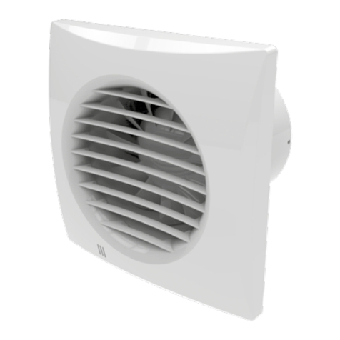
The product described in these operating instructions is an axial fan for Venting of small and
medium-sized living spaces that are heated in winter. The fan is made of white plastic.
The fan is compatible with pipes Ø 100, 125, 150 mm. depending on the flange size of the fan
The design of the fans is constantly being improved and updated, and some models may differ
from what is described in this manual.
OPERATING INSTRUCTIONS
The fan is designed for connection to the AC mains with a voltage of 220-240 V and a frequency of 50 Hz.
The fan is designed for continuous operation with a permanent power supply.
Degree of protection against ingress of foreign bodies and protection against water: IP 34
The fans are designed for use in ambient temperatures from + 1 ° C to + 45 ° C. The fan
does not have to be earthed.
4th

DE
ASSEMBLY
The fan is for ceiling or wall mounting and ventilation through a ventilation shaft or a ventilation pipe
with a corresponding diameter designed, Fig.1
Assembly order:
Step 1 - turn off the power supply and prepare the room for the fan assembly, Fig. 2-3; Step 2 - remove
the front grilles from the fan, Fig. 4;
Step 3 - the Attachment points mark for the fan, drill and the fan attach, Fig. 5-7; Step 4 - the fan to the
power gridconnect, if necessary, set the follow-up time and the humidity setpoint, if necessary, Fig. 8-14;
Step 5 - put the front grille back on the case, Fig. 15; Step 6 - Apply
power to the fan, Fig. 16.
DESCRIPTION OF TERMINALS ON THE CIRCUIT DIAGRAMS
L - phase (only for mains 220-240 V)
N - 0 (only for mains 220-240 V)
LT (ST) - control line of the timer; S -
external off / on switch.
ELECTRONIC CONTROL LOGIC
The fan with the time switch T - the fan starts after actuating the external switch, e.g. light switch. The signal
from the switch applies the control voltage to the input terminal LT (ST). After disconnecting the control
voltage, the fan continues to operate for the set time, from 2 to 30 minutes.
5

DE
The fan with the time switch and humidity sensor TH - the fan starts after the external switch, e.g. light switch,
has been actuated. The signal from the switch applies the control voltage to the input terminal LT (ST). The fan
also starts when the room humidity is above the switch-on humidity, adjustable from 60% to 90%. After
disconnecting the control voltage or after reducing the humidity, the fan continues to operate for the set
time, from 2 to 30 minutes.
To recruitment of maximum humiditySetpoint turn the potentiometer knob up to the H max position (90%).
To adjust the run-on time, turn the rotary knob of the potentiometer T clockwise to increase and
counterclockwise to reduce the run-on time accordingly, Fig. 12. To adjust the humidity setpoint, turn the
potentiometer rotary knob H clockwise to enlarge and counterclockwise corresponding to the reduction of
the moisture threshold, Fig. 12.
Warning! The circuit board of the timer is under mains voltage! Before any setting work, disconnect the fan from the
power supply! A plastic screwdriver for changing the settings is included with the fan. Use the plastic screwdriver to set
the switch-on delay time, follow-up time and the humidity setpoint, Fig. 14.
Do not use a metal screwdriver, knife, etc. to avoid damaging the electronic board.
6th

DE
MAINTENANCE
The maintenance work on the fan must be carried out at least once every 6 months.
Maintenance sequence:
disconnect the fan from the mains (fig. 17);
remove the front panel, fig. 18;
Clean the fan with a soft cloth and a brush moistened with a cleaning solution.
Rinse the grille under running water, fig. 19-21; rub the
surfaces dry;
place the cover back on the fan (Fig. 22); Apply the power
supply (Fig. 16).
WARNING! Protect the electrical components from splashing water!
STORAGE AND TRANSPORT REGULATIONS
Transporting the device is permitted with any type of vehicle.
The device is in its original packaging in a ventilated room at a temperature of + 5 ° C to
+ 40 ° C and a relative humidity of max. 80%.
Dust, acid and alkali vapors, which can cause corrosion, are not permitted in the storage area.
MANUFACTURER'S WARRANTY
With the purchase of this product, the consumer confirms that he has the operating conditions, operating
regulations and operating, storage, transport, assembly, adjustment, connection, maintenance, repair
requirements and guarantee obligations that are specified in the documents submitted by the manufacturer
are set out, have taken note of and agree to this.
The manufacturer sets the warranty period of 24 months from the date of sale of the product through
retail, on condition that the regulations for transport, storage, assembly and operation are met by the
consumer.
If malfunction occurs during the warranty period through the fault of the manufacturer, the
consumer is entitled to remedy the defect free of charge.
7th

DE
The guarantee service consists in carrying out work related to the rectification of defects in the product in
order to ensure that this product is used properly by the consumer. Defects are rectified by replacing or
repairing the product or a component of such a product.
DANGER! To carry out the warranty service, you need to present the operating instructions and
the payment receipt with the date of sale. The model of the product must match the model
specified in the operating instructions.
To perform the warranty service, contact Your dealer.
If the on-site guarantee is not possible, you will be provided with the necessary information about this
service.
The manufacturer does not issue a guarantee in the following cases:
the consumer does not present the product in its entirety, as stated in the operating instructions or other
document, including the components dismantled by the consumer;
if the model, the brand of the product and the information on the packaging and in the instruction
manual or any other document that replaces the instruction manual do not match if the product is not
serviced in good time (dust, condensation oil, particle contamination);
in the case of external damage caused by the consumer (external changes to the product that are
necessary for assembly are not deemed to be damage);
Changes to the design of the product or rework;
Replacement and use of units, spare parts and accessories (components) of such a product that are not
intended by the manufacturer;
improper use;
Failure to comply with operating instructions from the consumer;
Connection to the mains with a higher voltage than specified in the operating instructions;
8th

DE
Voltage jumps that put the product out of operation;
if the consumer independently carries out repairs to the product;
if repairs are carried out by third parties who have not been commissioned by the manufacturer; after
the warranty period has expired;
Failure to comply with stipulated conditions of carriage that ensure damage and / or destruction of the
product;
Failure to comply with storage conditions by the consumer; unlawful acts
by third parties in relation to the product;
in the event of force majeure (fire, flood, earthquake, war, fighting, blockade); Absence of sealing
seals, if these are provided for in the operating instructions; Lack of guarantee certificate;
Lack of Payment receiptconfirming the purchase, indicating the date of sale.
The manufacturer is liable for defects that arose through his fault before the product was handed over
to the consumer.
The manufacturer is not liable for defects that arise after delivery of the product to the consumer as a
result of non-compliance with transport, storage, assembly and operating regulations, actions by third
parties or force majeure.
The manufacturer is not liable for damage to the health and property of the consumer as a result of non-
compliance with the operating instructions by the consumer, as a result of improper use of the product, as a
result of the consumer failing to observe the warnings in the operating instructions and other information about
the product, as a result of non-compliance with transport, Storage, assembly, maintenance and operating
regulations.
9

1
10

L. N
QF
23
4th 5
6th 7th
11

/ V / _ default
L (~ *)
N (~ *) S.
QF
QF
S. L (~ *)
N (~ *)
8th
T / TH
L (~ *)
N (~ *) S.
QF
QF
L (~ *)
LT (ST *)
S.
N (~ *)
9
12th

T / TH
T
-+H
-+
2min
30 min 60% 90%
10 Т1 11
12th 13
13
H

MAINTENANCE ENTRIES
QF
14th 15th
16 17th
18th 19th
14th

Sign of the customer Sold
(Name and stamp of the
seller)
manufacturing date Date of sale
15th

Acceptance certificate
T
100
125
150
AV
TH
The fan is recognized as operational.
www.vlano.de VLANO01- (M model) DE-01
Table of contents
Other Vlano Fan manuals
Popular Fan manuals by other brands

Casablanca
Casablanca Continental owner's manual
Munters
Munters WM54F Manual for use and maintenance including assembling instructions
Turn of the century
Turn of the century Knit owner's manual

V-TAC
V-TAC VT-5547 Installation instruction
Klarstein
Klarstein 10031083 user manual
Salda
Salda VKA 125 EKO Installation instruction

