TeraRanger One Connection User manual

Instruction Manual for:
TeraRanger One
Connection to Pixhawk
Autopilots
Published March 2018
Table of contents:
1Introduction
2 Compatibility table
3 Wiring Connection to Pixhawk
3.1 TeraRanger One wiring connection –Pixhawk 2.1
3.2 TeraRanger One wiring connection –Pixhawk 1
4 Setup the onboard firmware
4.1 PX4 –QGroundControl
4.2 ArduCopter –QGroundControl
4.3 ArduCopter –APM Planner 2
4.4 ArduCopter –Mission Planner
1 Introduction

The purpose of this document is to explain how to connect a TeraRanger One sensor to
a Pixhawk board through the I2C interface and how to setup PX4 or ArduPilot firmware
to enable TeraRanger One sensor use.
2 Compatibility table
Sensor Version
Firmware Version compatibility
TR-One
–PX4: from Flight Stack v1.6.5 onwards
–APM: from Copter v3.5.3 onwards
3 Wiring Connection to Pixhawk
3.1 TeraRanger One wiring connection –Pixhawk 2.1
For brevity we will refer to the TeraRanger One distance sensor module as TR-One.
Please make sure you have a TR-One and a TR-I2C adapter:
1. TR-One sensor
2. TR-I2C adapter
To connect the sensor to the Pixhawk, please solder the power cable to the I2C adapter
as described below:
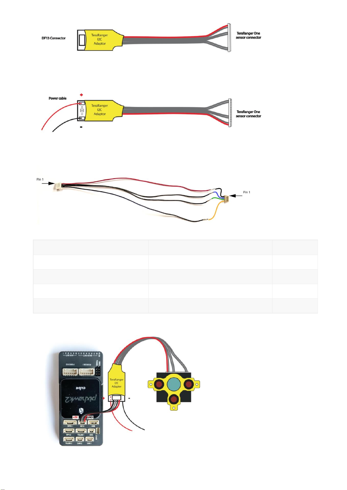
Take the I2C cable included in the Pixhawk 2.1 box and make your own connection as
described below:
TR-I2C Adapter pins
Pixhawk 2.1 I2C port pins
Color
1 VCC
1 VCC
Orange
2 SCL
2 SCL
Green
3 SDA
3 SDA
Blue
4 GND
4 GND
Black
Now connect the I2C adaptor to the Pixhawk and the TR-One to the I2C Adaptor:
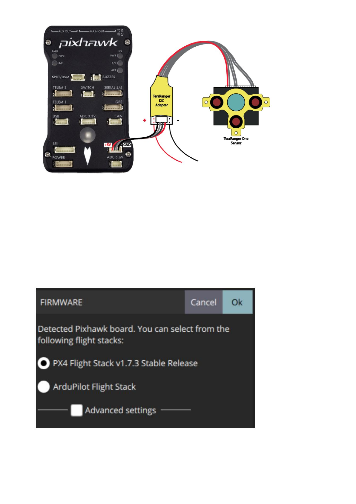
3.2 TeraRanger One wiring connection –Pixhawk 1

To connect the sensor to the Pixhawk, please solder the power cable to the I2C adapter
as described below:
Now connect the I2C adaptor to the Pixhawk via a DF13 4S cable (included in the
Pixhawk box) and the TR-One to the I2C Adaptor:
TR-I2C Adapter pins
Pixhawk I2C port pins
1 VCC
1 VCC
2 SCL
2 SCL
3 SDA
3 SDA
4 GND
4 GND
4 Setup the onboard firmware
4.1 PX4 –QGroundControl
Note: Please always use the latest QGroundControl version, available
from: https://docs.qgroundcontrol.com/en/getting_started/download_and_install.html
1. Launch QGroundControl software
2. Open Vehicle setup menu and go into the Firmware tab (unplug and replug
autopilot if needed).
Select the latest stable release of PX4 Flight Stack. Press the Ok button to flash the
autopilot.
3. Go to Parameters/Sensor Enable
In the field SENS_EN_TRANGER select your TeraRanger sensor type:
•TROne
Press Save to confirm.
Table of contents


