2G1429SAB 㻔KRB-0951b㻕
ȖȬȸǫȞǦȳȈࡸٳᢿદ˺ȏȳȉȫ
ӕৢᛟଢ
Breaker-Mounted External Operating Handle
Instruction Manual
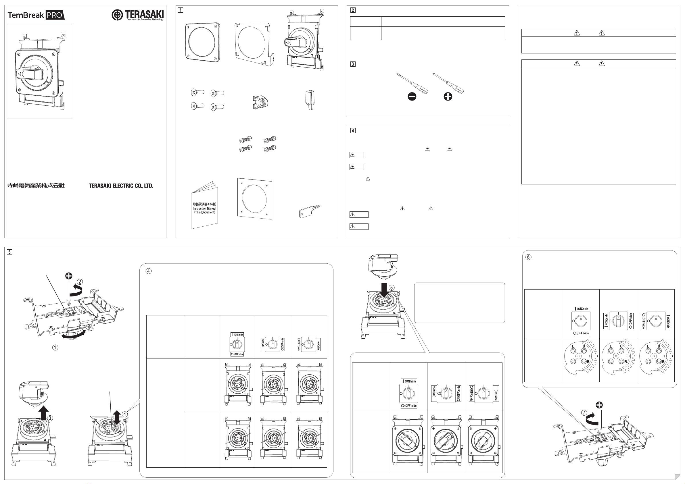
࢟ࡸ
(Type): TPHB63S
ᮏᶵࡣ㸪࣮ࣔࢱ࣮ࢥࣥࢺ࣮ࣟࣝࢭࣥࢱ࣮ࡸ㓄
㟁┙ෆ⤌㎸ࢇࡔ㐽᩿ჾࢆ┙እࡽᡭື࡛᧯
సࡍࡿ⨨࡛ࡍࠋ
This device allows the breaker installed in a motor
control center or switchboard to be operated manually
without the need for opening the panel of the motor
control center or switchboard.
ᮏ᭩ࡣ㸪ࡈ⏝࡞ࡿ᪉ࡢ࠾ᡭඖ࡛ษಖ⟶ୗࡉ࠸ࠋᮏ᭩グ㍕ࡢ࡞࠸ྲྀᢅ
࠸㸪ཬࡧㄗࡗࡓྲྀᢅ࠸ࡼࡾ⏕ࡌࡿᦆᐖ㛵ࡋ࡚㸪ᘢ♫ࡣ㈐௵ࢆ㈇࠸ࡲࡏࢇࠋ
Please retain this manual for future reference. The Manufacturer assumes no responsibility for
damages resulting from non-application or incorrect application of the instructions provided herein.
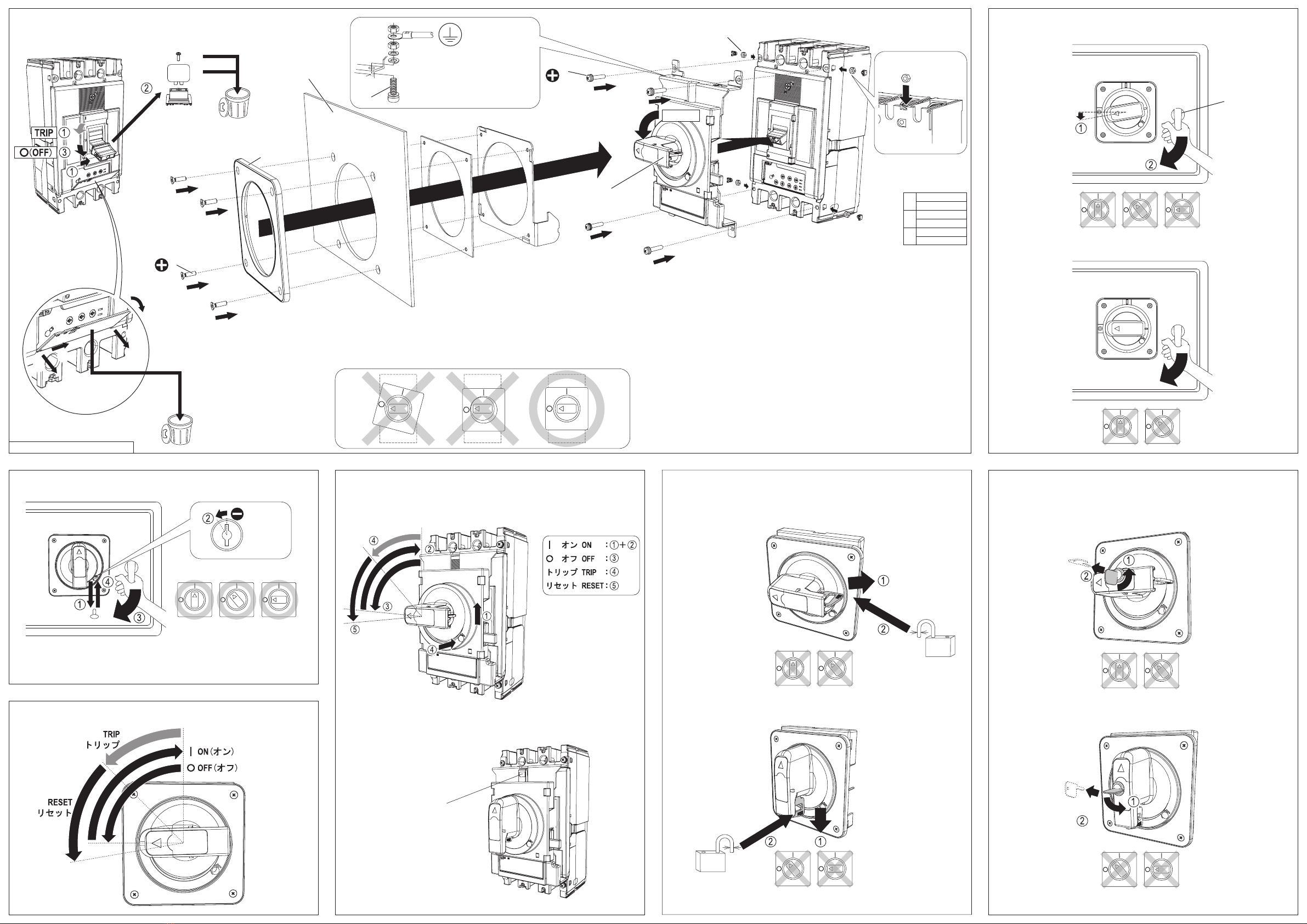
ᢚૺ֥ӕ˄ƚ૾Ӽ٭ᙲ
The Mounting Direction Changing Procedure
ࣁࣥࢻࣝ࢟ࣕࢵࢳࡽࡡࡌ㢌ࡀぢ࠼
ࡿ⨨ࡲ࡛ࣁࣥࢻࣝࢆᅇࡋࡲࡍࠋ
Rotate the handle until the screw head is
visible at the handle catch.
ϋܾཋɟᚁ Packaged Items
⢝ᯈ 㔠 ࣁࣥࢻࣝ
Panel plate Hook holder Handle
ࡉࡽࡡࡌ㯮M414 - 4pcs.
Flat head screws black
㜵ሻࣃࢵ࢟ࣥ㸦࢜ࣉࢩࣙࣥ㸧 ࣮࢟㸦࢜ࣉࢩࣙࣥ㸧
Gasket for dust protection optionalKey optional
ᢘဇᢚૺ֥࢟ࡸ Applicable Breaker Types
ࣁࣥࢻࣝᙧᘧ
Handle type
㐺⏝㐽᩿ჾᙧᘧ
Applicable breaker types
TPHB63S
䝘䝑䝖䝩䝹䝎䞊㻔3ᴟ⏝㻕 4pcs.
Nut holder (for 3 poles)
䝘䝑䝖䝩䝹䝎䞊㻔㻠ᴟഃ⏝㻕㻌2pcs.
Nut holder (for 4 pole side)
PS400-
ڧڧ
, PS630-
ڧڧ
, PH400-
ڧڧ
, PH630-
ڧڧ
,
P400
ڧ
, P630
ڧ
࣏ᙲƱƳǔφ Assembly Tools
4.550 No.2
ܤμɥƷƝද Safety Notices
ᕤ㸪⏝㸪ಖᏲ࣭Ⅼ᳨ࡢ๓㸪ᚲࡎᮏ᭩ࡑࡢࡢᒓ᭩㢮ࢆ࠾ㄞࡳ㡬ࡁ㸪
ᶵჾࡢ▱㆑㸪Ᏻࡢሗ㸪ཬࡧὀព㡯ࡢ࡚⩦⇍ࡋ࡚ࡽ࠾ྲྀᢅ࠸ୗࡉ࠸ࠋ
ᮏ᭩࡛ࡣ㸪Ᏻὀព㡯ࡢࣛࣥࢡࢆࠕ ༴㝤ࠖ㸪ࠕ ὀពࠖ༊ศࡋ࡚࠸ࡲࡍࠋ
༴㝤㸸
ྲྀᢅ࠸ࢆㄗࡗࡓሙྜ㸪༴㝤࡞≧ἣࡀ㉳ࡇࡾ࠼࡚㸪Ṛஸࡲࡓࡣ㔜യࢆཷ
ࡅࡿྍ⬟ᛶࡀᐃࡉࢀࡿሙྜࠋ
ὀព㸸
ྲྀᢅ࠸ࢆㄗࡗࡓሙྜ㸪༴㝤࡞≧ἣࡀ㉳ࡇࡾ࠼࡚㸪୰⛬ᗘࡢയᐖࡸ㍍യ
ࢆཷࡅࡿྍ⬟ᛶࡀᐃࡉࢀࡿሙྜཬࡧ≀ⓗᦆᐖࡢࡳࡀᐃࡉࢀࡿሙྜࠋ
࡞࠾㸪ࠕ ὀពࠖグ㍕ࡋࡓ㡯࡛ࡶ㸪≧ἣࡼࡗ࡚ࡣ㔜࡞⤖ᯝ⤖ࡧࡘࡃྍ
⬟ᛶࡀ࠶ࡾࡲࡍࠋ࠸ࡎࢀࡶ㔜せ࡞ෆᐜ࡛ࡍࡢ࡛㸪ᚲࡎᏲࡗ࡚ୗࡉ࠸ࠋ
Be sure to read these Instructions and other associated documents accompanying the product
thoroughly to be familiarize yourself with the product handling, safety information, and all other
precautions before mounting, using, servicing, or inspecting the product. In these Instructions,
safety notices are divided into " Warning" and " Caution" according to the hazard level:
Warning :
A warning notice with this symbol indicates that neglecting the suggested procedure
or practice could be fatal or result in serious personal injury.
Caution :
A caution notice with this symbol indicates that neglecting the suggested procedure or
practice could result in moderate or slight personal injury and/or property damage.
ୗ⾲ࡼࡾ㸪ኚ᭦ࡍࡿ㐽᩿ჾྲྀࡅ᪉ྥᑐᛂ
ࡋࡓࣁࣥࢻࣝࡣࡵ㎸ࡳ⨨ࢆ㑅ࡧ㸪ࡣࡵ㎸ࡳ
ࡲࡍࠋ
Referring to the table below, install the handle in the
position matched to the change in breaker mounting
direction.
ࣁࣥࢻࣝࡣࡵ㎸ࡳ⨨ Handle installation positions
㐽᩿ჾྲྀࡅ᪉ྥ
Mounting direction
ୖ㟁※౪⤥ᙧ
for Upper power
supply type
ᕥ㟁※౪⤥ᙧ
for Left power
supply type
ྑ㟁※౪⤥ᙧ
for Right power
supply type
ࣁࣥࢻࣝ
ࡣࡵ㎸ࡳ⨨
Handle installation
positions
ᶆ‽Standard
Note that failing to observe caution notices could result in serious injury/damage in some situations.
Because safety notices contain important information, be sure to read and observe them.
༴㝤 Warning
ڦ⏝ୖࡢࡈὀព Operation Precautions
ە㟁➃Ꮚ㒊ゐࢀ࡞࠸࡛ୗࡉ࠸ࠋឤ㟁ࡢ࠾ࡑࢀࡀ࠶ࡾࡲࡍࠋ
Never touch live terminals. Doing so may result in electric shock.
ὀព Caution
ڦᕤୖࡢࡈὀព Installation Precautions
ە㟁Ẽᕤࡣ㸪᭷㈨᱁⪅㸦㟁Ẽᕤኈ㸧ࡀ⾜ࡗ࡚ୗࡉ࠸ࠋ
Electrical work should only be undertaken by suitably qualified persons.
ەᕤసᴗࡣ㸪ୖ㐽᩿ჾ࡞ࢆۑ㸦OFF㸧ࡋ㸪㟁ࡋ࡚࠸࡞࠸ࡇࢆ☜
ㄆࡋ࡚⾜ࡗ࡚ୗࡉ࠸㹿ឤ㟁ࡢ࠾ࡑࢀࡀ࠶ࡾࡲࡍࠋ
Prior to commencing any work on the product, open an upstream circuit breaker or isolator
to ensure that no voltage is applied to the product. Otherwise, electrical shock may result.
ە㓄㟁┙ࡢࣃࢿࣝࡢᅛᐃࡣ㸪ᮏᶵࡢࣃࢿࣝࣟࢵࢡࡣูᅛᐃ㔠ලࢆࡈ⏝
ពୗࡉ࠸ࠋᮏᶵࡢࡳ࡛ࡢࣃࢿࣝࡢᅛᐃࡣ㸪◚ᦆࡢཎᅉ࡞ࡾࡲࡍࠋ
To remain the switchboard panel closed securely, use appropriate hardware in addition to
the panel lock of the handle. Using the panel lock only may result in damage to the
switchboard panel.
ڦ⏝ୖࡢࡈὀព Operation Precautions
ە㐽᩿ჾࡀ⮬ືⓗࢺࣜࢵࣉ㸦㐽᩿㸧ࡋࡓሙྜࡣ㸪ཎᅉࢆྲྀࡾ㝖࠸࡚ࡽࣁ
ࣥࢻࣝࢆ㹺㸦ON㸧ࡋ࡚ୗࡉ࠸ࠋ㟁ὶ㸦▷⤡㟁ὶ㸧ࢆ㐽᩿ࡋࡓሙྜࡣ㸪
㐽᩿ჾࢆⅬ᳨ࡋ࡚ୗࡉ࠸ࠋⅆ⅏ࡢ࠾ࡑࢀࡀ࠶ࡾࡲࡍࠋ
When the breaker trips open automatically, remove the cause, then return the handle to
the |(ON) position. Should a fault be interrupted, the breaker must be inspected.
Otherwise, a fire may result.
ە᧯సࣀࣈ㐣࡞Ⲵ㔜ࢆຍ࠼࡞࠸࡛ୗࡉ࠸ࠋᦆയࡢཎᅉ࡞ࡾࡲࡍࠋ
Do not apply excessive force to the operating knob. Otherwise, damage may occur.
㸸ࣁࣥࢻࣝ࢟ࣕࢵࢳࡽෆ㒊ࢆぢ࡚㸪ኚ᭦ࡍࡿ㐽᩿ჾྲྀࡅ᪉ྥᑐᛂࡋ
ࡓࣁࣥࢻࣝࢠࣖࡢಀྜ࡞ࡗ࡚࠸ࡿࡇࢆୗ⾲ࡼࡾ☜ㄆࡋࡲࡍࠋ
Visually check the inside from the handle catch to see if the handle is engaged with
the gear properly. See the table below.
ࣁࣥࢻࣝࢠࣖࡢಀྜ Handle and gear engagement
㐽᩿ჾྲྀࡅ᪉ྥ
Mounting direction
ୖ㟁※౪⤥ᙧ
for Upper power
supply type
ᕥ㟁※౪⤥ᙧ
for Left power
supply type
ྑ㟁※౪⤥ᙧ
for Right power
supply type
ࣁࣥࢻࣝ
ࢠࣖࡢಀྜ
Handle and gear
engagement
ᶆ‽ Standard
㐽᩿ჾྲྀࡅ᪉ྥ
Mounting direction
ᵝ
Specifications
ୖ㟁※౪⤥ᙧ
for Upper power
supply type
ᕥ㟁※౪⤥ᙧ
for Left power
supply type
ྑ㟁※౪⤥ᙧ
for Right power
supply type
ࣟࢵࢡㄪᩚᯈࡢ
⤌᭰࠼⨨
Lock adjustment plate
orientations
ᅜෆྥࡅᵝရ
Japanese
Specifications
ᶆ‽ Standard
ᾏእྥࡅᵝရ
Overseas
Specifications
ᶆ‽ Standard
㸸ୗ⾲ࡼࡾ㸪ኚ᭦ࡍࡿ㐽᩿ჾྲྀࡅ᪉ྥᑐᛂࡋࡓࣟࢵࢡㄪᩚᯈࡢ⨨ࢆ㑅ࡧ㸪⤌᭰࠼
ࡲࡍࠋ࠼ࡤᕥ㟁※౪⤥ᙧࡢࣁࣥࢻࣝኚ᭦ࡍࡿሙྜ㸪ୗ⾲ࡼࡾ”B”ࡢ⨨ࣟࢵࢡㄪ
ᩚᯈࢆ⤌᭰࠼ࡲࡍࠋ
Orient the lock adjustment plate depending on the changes in breaker mounting direction. When
changing the handle to the left power supply type, for example, select orientation "B" from the table
shown below.
ࣟࢵࢡㄪᩚᯈࡢ⤌᭰࠼⨨ Lock adjustment plate orientations
࡞ࡡࡌM516- 4pcs.
Pan head screws
a
a
b
a
a
b
a
ba
ࣁࣥࢻࣝ࢟ࣕࢵࢳ No.2
Handle catch
ࣟࢵࢡㄪᩚᯈ㹠㸦ࣉࣛࢫࢳࢵࢡ㸧
Lock adjustment plate b (Plastic)
࣭ᾏእྥࡅᵝရࡢࡳ
࣭For overseas specifications
ࣟࢵࢡㄪᩚᯈ㹟㸦㔠ᒓ㸧
Lock adjustment plate a (Metal)
1.5 - 2.0N㺃mNo.2
AB C
AB C
〒547-0002
大阪市平野区加美東6
–
13
–
47
TEL 06
–
6791
–
2756
FAX 06
–
6791
–
2732
https://www.terasaki.co.jp
6-13-47 Kamihigashi, Hiranoku, Osaka
547-0002, Japan
TEL +81-6-6791-2763
FAX +81-6-6791-2732
https://www.terasaki.co.jp