Terex T25 Guide

Operator/Service & Parts Manual
First Edition
Rev A1
Part No. 833008
T25/T45

Operating Instructions and Parts Manual
2 Terex T25I and T45I Super Quiet Generator
June 2006
REV A
Table Of Contents
INTRODUCTION......................................................................................... 5
DESCRIPTION OF EQUIPMENT................................................................ 5
GENERAL SAFETY.................................................................................... 6
SAFETY SIGN LOCATIONS ...................................................................... 7
RECEIPT OF DELIVERY CHECKLIST..................................................... 10
TRANSPORT & TOWING......................................................................... 11
SETUP ...................................................................................................... 11
OPERATING INSTRUCTIONS ................................................................. 13
MAINTENANCE........................................................................................ 19
TROUBLESHOOTING GUIDE.................................................................. 22
ELECTRICAL TROUBLESHOOTING ...................................................... 27
T25I / T45I SPECIFICATIONS AND DIMENSIONS.................................. 37
TORQUE SPECIFICATIONS .................................................................... 39
GENERATOR TORQUE SPECIFICATIONS ............................................ 39
SERVICE PARTS FAX ORDER FORM .................................................... 41
PARTS CATALOG ................................................................................... 43
CABINET DECALS................................................................................... 44
SAFETY DECALS .................................................................................... 45
FIGURE 1 - BASE W/FUEL TANK ........................................................... 46
FIGURE 2 - BASE W/LIFTING EYE & BATTERY.................................... 48
FIGURE 3 - GENSET................................................................................ 50
FIGURE 4 - CABINET ASSEMBLY.......................................................... 52
FIGURE 5 - CABINET ASSEMBLY W/DOORS ....................................... 54
FIGURE 6 - CONTROL PANEL ASSEMBLY- UPPER............................. 56
FIGURE 7 - CONTROL PANEL ASSEMBLY - LOWER........................... 58
FIGURE 8 - DISTRIBUTION PANEL ........................................................ 60
FIGURE 9 - MUFFLER ASSEMBLY......................................................... 62

Terex T25I and T45I Super Quiet Generator 3
Operating Instructions and Parts Manual
June 2006
REV A
Table Of Contents
FIGURE 10 - AIR CLEANER ASSEMBLY ............................................... 64
FIGURE 11A - ENGINES - T25I................................................................ 66
FIGURE 11B - ENGINES - T45I................................................................ 68
FIGURE 12 - VOLTAGE SELECTOR SWITCH........................................ 70
FIGURE 13 - TRAILER ............................................................................. 72
FIGURE 14 - OPTIONS............................................................................. 74

Operating Instructions and Parts Manual
4 Terex T25I and T45I Super Quiet Generator
June 2006
REV A
TEREX Model Number _____________________ Serial Number ____________________________
Engine Model Number______________________ Serial Number ____________________________
Generator Model Number ___________________ Serial Number ____________________________
Owner:__________________________________ Ship to: _________________________________
Options:_________________________________
_______________________________________
_______________________________________
_______________________________________
_______________________________________
P.O. Box 3147 (29732)
590 Huey Road
Rock Hill, SC 29730
Telephone: (800) 433-3026
FAX: (803) 366-1101
This Operation and Service Manual contains information specifically pertaining to the operation and
maintenance of the TEREX T25I and T45I Super Quiet Generators. We suggest that you read this
manual carefully prior to operating the generator. This manual should be retained and refered to for
operation, maintenance and ordering parts. When ordering parts, PLEASE INCLUDE THE MODEL AND
SERIAL NUMBER located on the nameplate of the generator . For major repair and service or other
information, contact your TEREX dealer, or call or write to:

Terex T25I and T45I Super Quiet Generator 5
Operating Instructions and Parts Manual
June 2006
REV A
INTRODUCTION
Owners, Users, and Operators:
TEREX appreciates your choice of our product for
your application. Our number one priority is user
safety which is best achieved by our joint efforts.
We feel that you can make a major contribution to
safety if you as the equipment users and opera-
tors:
• Comply with OSHA, Federal, State, and Local
Regulations.
• Read, Understand, and Follow the
instructions in this and other manuals supplied
with this product.
• Use Good, Safe Work Practices in a common
sense way.
• Only have trained operators — directed by
informed and knowledgeable supervision —
operating this product.
If there is anything in this manual that is not clear
or which you believe should be added, please
send your comments to TEREX Service Depart-
ment in Rock Hill, SC.
DESCRIPTION OF EQUIPMENT
The engine/generator assembly consists of a
diesel engine combined with an electrical genera-
tor. This assembly is firmly bolted together to form
an integral unit and does not require anything
other than routine maintenance.
The engine is equipped with a 12-volt starter (24-
volt starter optional) and can be wired for remote
starting capability at the control panel.
A dry-element air cleaner is standard equipment to
ensure a clean air supply, and a remote fuel/water
separator is included for additional fuel system
protection.
A governor on the engine provides a stable
operating speed under varying load conditions,
and the generator is equipped with a solid-state
voltage regulator to stabilize the output voltage
under these same conditions. Figures and
schematics of both the governor and regulator are
provided in the ENGINE and GENERATOR
OPERATOR’S MANUALS.
An automatic shutdown system is incorporated in
the generator set to sense low oil pressure and/or
high coolant temperature, and in either case the
engine/generator assembly will automatically
cease operation.
A diesel fuel tank is incorporated within the base
of the unit to ensure an uninterrupted operating
cycle under full load. The engine/generator
assembly is mounted to the base using high
durometer vibration isolators.
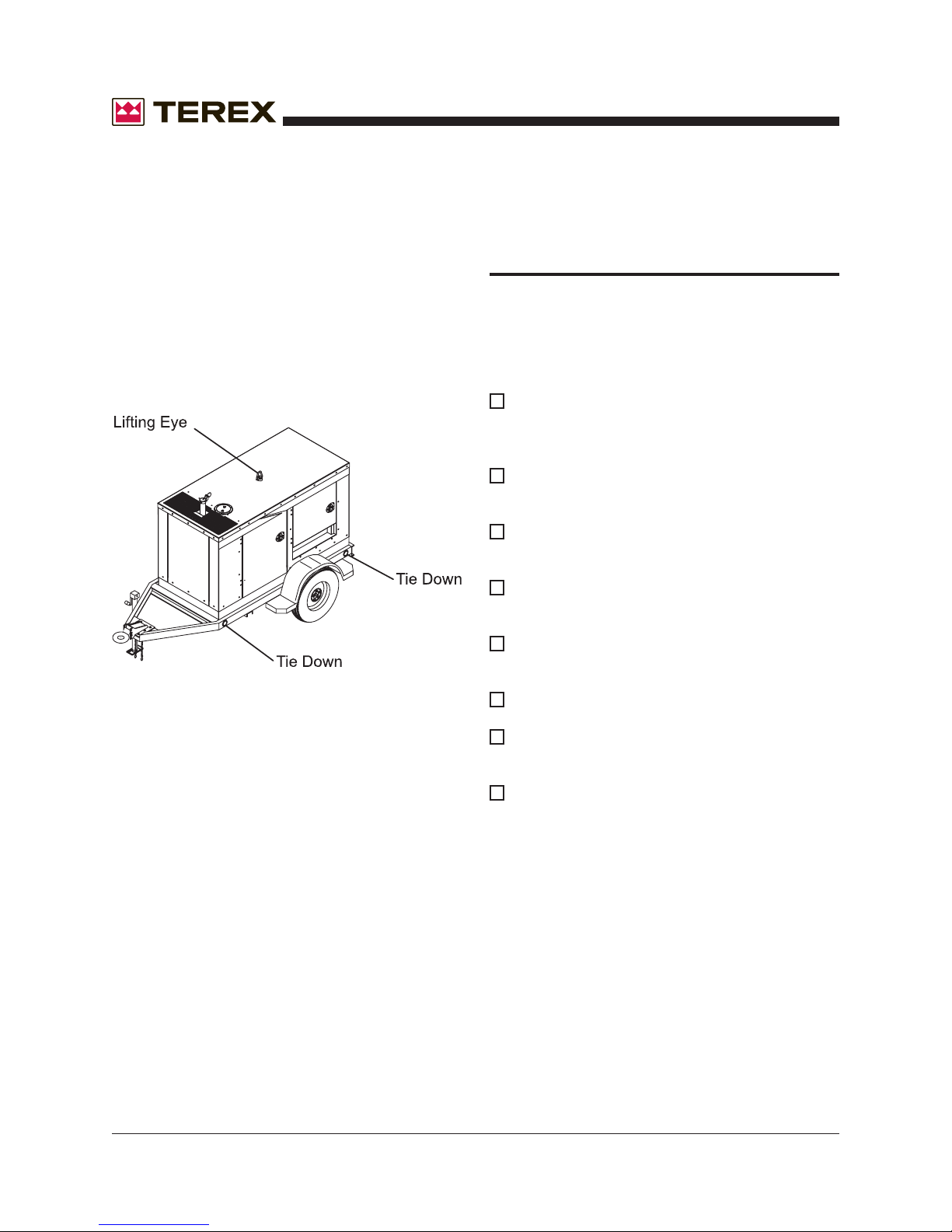
The enclosure for the generator set is constructed
from 12 or 14-gauge sheet metal to ensure
maximum rigidity, and is bolted together to allow
easy access to major components if necessary.
Four lockable, hinged access doors are provided
for routine operation and maintenance.
The enclosure on the Super Quiet Generator is
specifically designed for a high degree of sound
attenuation. This allows the generator set to be
operated in noise-sensitive environments. The
interior of the enclosure is coated with sound-
dampening polymer foam that is highly effective in
noise suppression and is impervious to water, fuel,
and oil.
A high ambient temperature radiator and a critical
grade exhaust silencer are contained within the
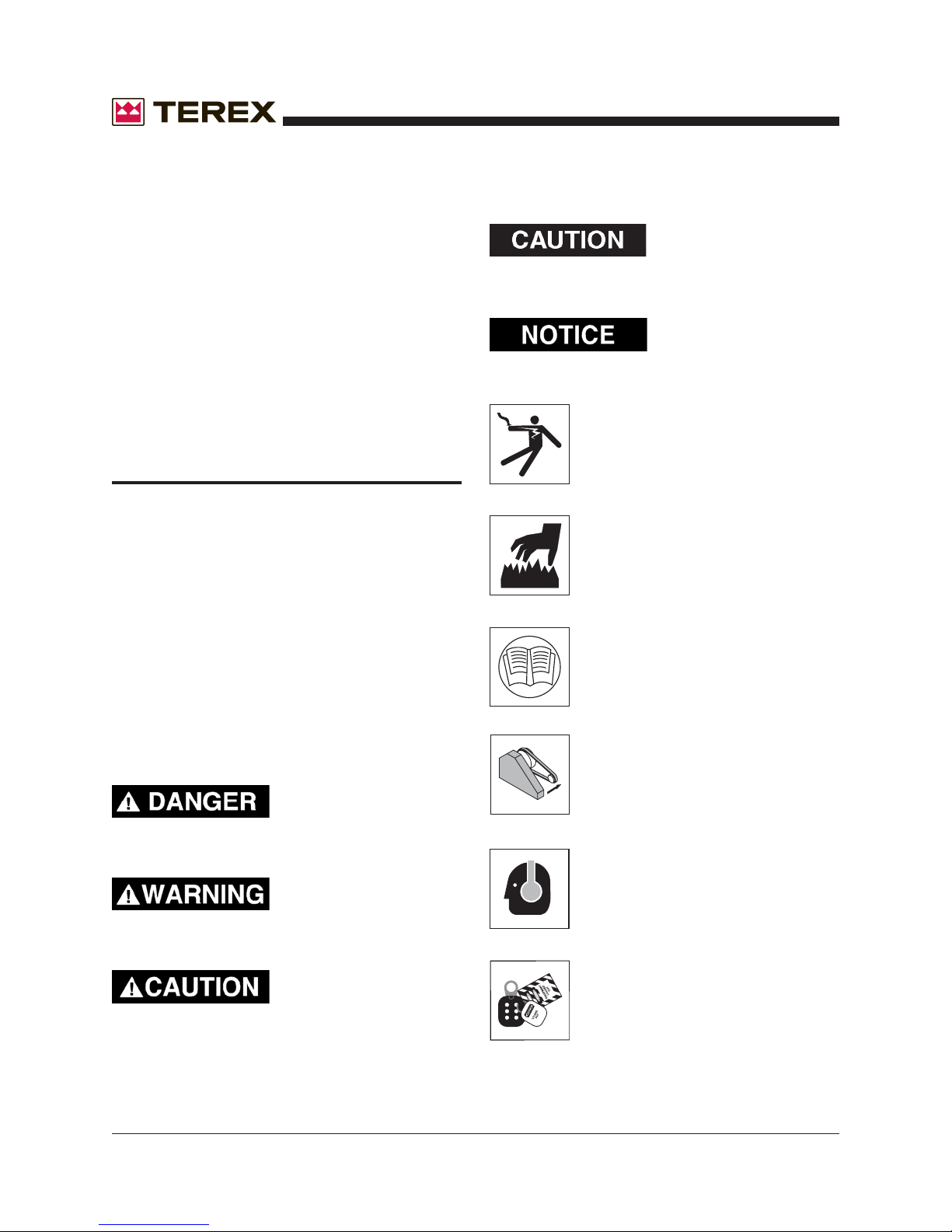
THE SAFETY ALERT SYMBOL IS USED TO
ALERT YOU TO POTENTIAL PERSONAL
INJURY HAZARDS. OBEY ALL SAFETY
MESSAGES THAT FOLLOW THIS SYMBOL
TO AVOID POSSIBLE INJURY OR DEATH.

Operating Instructions and Parts Manual
6 Terex T25I and T45I Super Quiet Generator
June 2006
REV A
GENERAL SAFETY
HAZARD CLASSIFICATION
A multi-tier hazard classification system is used to
communicate potential personal injury hazards.
The following signal words used with the safety
alert symbol indicate a specific level of severity of
the potential hazard. Signal words used without
the safety alert symbol relate to property damage
and protection only. All are used as attention-
getting devices throughout this manual as well as
on decals and labels fixed to the machinery to
assist in potential hazard recognition and preven-
tion.
Red - Indicates an
imminently hazardous
situation which, if not avoided, will result in death
or serious injury.
Orange - Indicates a
potentially hazardous
situation which, if not avoided, could result in
death or serious injury.
Yellow with safety alert
symbol - Indicates a
potentially hazardous situation which, if not
avoided, may result in minor or moderate injury.
Yellow without safety
alert symbol - Indicates a
situation which, if not avoided, may result in
property or equipment damage.
Green - Indicates impor-
tant installation, operation
or maintenance information.
Hazardous voltage. Will cause
serious injury or death.
Hot exhaust. Can contain carbon
monoxide. Will cause serious injury
or death.
Read all manuals that shipped with
your equipment. Maintenance is
done more easily and safely when
you know what you're doing.
Keep all guards in place.
Wear hearing protection when you
are near this equipment.
Lockout and Tagout. Equipment may
be energized. Lockout and tagout all
energy sources prior to performing
maintenanceadjustments.
enclosure as standard equipment.
A center-point lifting attachment is located in the
top of the enclosure to allow crane lifting of the
entire unit.
The generator set is mounted on a trailer equipped
for highway operation. Hydraulic surge brakes are
standard on larger generator sets for maximum
stopping efficiency. Electric brakes are also
available as an option.
DESCRIPTION OF EQUIPMENT (Cont.)

Terex T25I and T45I Super Quiet Generator 7
Operating Instructions and Parts Manual
June 2006
REV A
GENERAL SAFETY (Cont.)
SAFETY SIGN LOCATIONS

Operating Instructions and Parts Manual
8 Terex T25I and T45I Super Quiet Generator
June 2006
REV A
EXHAUST GASES ARE TOXIC. DO NOT USE
INDOORS UNLESS PROPERLY VENTILATED
OR AN EXHAUST SCRUBBER IS USED.
Check exhaust system regularly for leaks and
ensure that the exhaust manifolds are secure and
not warped. Make sure the unit is well ventilated.
GENERAL SAFETY (Cont.)
Use protective clothing and safety equipment.
Always wear approved safety equipment such as
gloves, safety boots, safety hard hat, goggles, ear
protection, and dust masks when necessary.
Wear protective clothing that is snug and belted
where required.
UNAUTHORIZED WELDING
UNAUTHORIZED WELDING CAN CAUSE
STRUCTURAL FAILURE OR PERSONAL
INJURY.
DO NOT weld on any structural member.
Any unauthorized welding or repair procedure
will void the warranty.
ACCIDENT PREVENTION
ALWAYS handle fuel with care. It is highly
flammable.
ALWAYS stop engine before refueling. Fill
fuel tank outdoors.
DO NOT replace fuel lines with materials
different from those supplied as original
equipment.
FIRES CAN CAUSE SEVERE PERSONAL
INJURY OR MACHINE DAMAGE.
Prevent fires by keeping the generator and its
surrounding area clean.
DO NOT refuel while smoking or when near
open flame or sparks.
DO NOT refuel the engine when it is hot.
Allow to cool for several minutes before
refueling.
DO NOT spill fuel inside the engine compartment.
If fuel has leaked, wipe it up and have leak
repaired before next use.
ALWAYS Have a fire extinguisher nearby. Be
sure the
extinguisher is properly maintained and be
familiar with its use. Extinguishers rated ABC
by the NFPA are appropriate for all applications.
FUELING

Terex T25I and T45I Super Quiet Generator 9
Operating Instructions and Parts Manual
June 2006
REV A
ELECTRICAL SAFETY
THIS EQUIPMENT USES HIGH VOLTAGE CIR-
CUITS CAPABLE OF CAUSING SERIOUS IN-
JURY OR DEATH. EXERCISE EXTREME CAU-
TION AROUND ANY ELECTRICAL COMPO-
NENT WHILE OPERATING THIS UNIT.
Always ground the unit according to local
codes. A grounding lug has been added to the
base frame for your convenience.
Beware of cut or damaged power cords. Have a
qualified electrician replace any damaged cords
immediately.
DO NOT TOUCH HOT PARTS.
The exhaust manifold and tail pipe are very hot.
Parts of the engine are also hot. Use protective
gloves when handling hot parts.
BATTERY HAZARDS
LEAD ACID BATTERIES CAN BE DANGER-
OUS. THE SULFURIC ACID IN THE BATTERY
CAN CAUSE SEVERE SKIN AND EYE BURNS.
THE HYDROGEN GAS EMITTED DURING
CHARGING CAN EXPLODE IF AN ARC OR
FLAME IS PRESENT.
DO NOT smoke while servicing the battery.
DO NOT allow tools to touch battery terminals and
create an arc.
Disconnect the negative terminal of the battery
when working on the engine or other parts to
prevent accidental arcing. Disconnect the negative
cable at the end away from the battery.
DO NOT remove the vent caps when charging the
battery.
Always wear eye protection when servicing the
battery.
If acid gets on skin or eyes, immediately flush
under running water and obtain medical
attention.
KEEP ALL BODY PARTS AND CLOTHING
AWAY FROM MOVING PARTS.
Loose jackets, shirts, sleeves, jewely and espe-
cially neckties should not be worn while working
on or running the unit.
Only remove guards or protective devices from
unit temporarily to gain access for maintenance.
Always replace guards immediately after servic-
ing. Never remove guards while unit is operating.
Keep your hands away from moving parts, particu-
larly clear of the radiator fan and alternator belts
when the engine is running.
BEWARE OF TRAFFIC HAZARDS
Stand clear of traffic when starting or checking the
unit along the road.
Check the fuel tank, oil pan, and fuel and oil lines
for leaks that would spill fuel or oil on the road.
Check fasteners and mounting brackets periodi-
cally to insure all are tight and nothing is in danger
of falling off during transit.
GENERAL SAFETY (Cont.)

Operating Instructions and Parts Manual
10 Terex T25I and T45I Super Quiet Generator
June 2006
REV A
BE CAREFUL WHEN LIFTING. NEVER SUS-
PEND ANY OTHER EQUIPMENT FROM THE
SHIPPING TIE DOWNS.
Use the lifting eye for lifting the trailer (with cabi-
net). Make sure any tie-downs at the bottom of the
trailer are released prior to lifting.
NEVER CLIMB ON TOP OF THE CABINET.
RECEIPT OF DELIVERY
CHECKLIST
The generator will be serviced, tested and ready
for operation upon delivery. Terex recommends
the following checks:
Insure there is no freight handling damage
which should be charged against the
carrier.
Check the front jack for security and proper
operation.
Check that the tires are not damaged, under
inflated or that any lugs are loose.
Check the engine/generator for obvious
damage, loose connections, or leaks.
Check the control panel for damage or loose
connections.
Check the exhaust system for damage.
Check all fluid levels; battery, radiator, and
engine oils.
Ensure manuals are in the pocket provided
inside the unit.
GENERAL SAFETY (Cont.)

Terex T25I and T45I Super Quiet Generator 11
Operating Instructions and Parts Manual
June 2006
REV A
TRANSPORT & TOWING
All trailer-mounted Terex Super Quiet Pac genera-
tors are designed for highway and off road
towing capability. Please consult state and local
transportation codes before transporting the
generator set. Additionally, all state and local
traffic laws take precedence over the following
instructions whenever differences arise between
them.
• Make sure the towing vehicle is of adequate
size to both tow and stop the unit.
• Disconnect all wiring and cabling (including the
ground wire) from the generator set.
• Close and latch or lock all access doors.
• Using the front leveling jack, raise the trailer
hitch to an adequate height so that the
generator can be securely attached to the
transporting vehicle.
• Ensure that the coupler is properly secured to
the towing vehicle and attach the safety chains.
Attach the “breakaway” chain on the surge
brake and the electrical coupler if these options
are included on the unit.
ALWAYS USE THE PROPER TRAILER HITCH
AND SAFETY CHAINS. OBEY ALL
LOCAL OR STATE D.O.T. LAWS WHEN TOW-
ING A GENERATOR.
FAILURE TO PROPERLY SECURE THE
TRAILER TO THE TOWING VEHICLE MAY
RESULT IN SERIOUS INJURY OR DEATH.
• Retract and rotate the front leveling jack into its
stowed position.
EXCEEDING THESE RECOMMENDED SPEEDS
CAN CAUSE SEVERE DAMAGE TO THE UNIT.
DAMAGE CAUSED BY THESE
UNSAFE PRACTICES WILL VOID THE
MANUFACTURER’S WARRANTY.
SETUP
Move the generator set to the desired location
keeping the following in mind:
• The spot where the generator set is positioned
should be relatively level.
• The location selected should be centrally
located to equipment requiring the loads to
minimize voltage drop in the power cord.
• Locate so power cords can be routed without
crossing roads and access routes.
• Locate where the engine will get good
ventilation. Do not locate where fumes will enter
a building.
• Do not place beside a building wall that would
reflect and intensify noise.
Unhitch from the towing vehicle as follows:
• Locate the generator set in the desired location.
• Check the tires for proper inflation and verify
that the lug nuts are tight.
• If equiped with towing lights, connect the
electrical coupler to the towing vehicle.
• Observe posted speed limits for trailers.
Generally, do not exceed 45 mph on paved
roads and 10 mph on unpaved roads.
GENERAL SAFETY (Cont.)

Operating Instructions and Parts Manual
12 Terex T25I and T45I Super Quiet Generator
June 2006
REV A
THE WHEELS MUST BE PROPERLY CHOCKED
IF THE GENERATOR IS ON UNLEVEL
GROUND. DO NOT OPERATE THE GENERA-
TOR SET UNTIL IT HAS BEEN PROPERLY SE-
CURED.
When preparing to start the generator set, follow
the sequence listed below:
• Check the coolant level in the radiator, and add
as necessary. If adding coolant, use only a
50/50 mixture of antifreeze and water. Refer to
your engine manufacturer's maintenance
manual for specific antifreeze information.
NEVER REMOVE THE RADIATOR CAP WHILE
THE ENGINE IS RUNNING OR WHILE THE
ENGINE IS HOT.
• Check the oil level in the engine crankcase, and
add as required.
USE CLASS API, CC OR CD GRADE ENGINE
OIL. REFER TO ISUZU ENGINE MANUAL FOR
VISCOSITY AND QUANTITY.
• If the battery is not a maintenance free battery,
check the electrolyte level in the battery and
add distilled water if necessary.
• Check fuel/water separator for water in the fuel
system. Drain water from separator if
necessary.
• Check fuel level in the fuel tank and add as
required. Check to insure the fuel tank vent is
“open” and not clogged.
• If the axle is sloped downhill, turn the generator
set so that the axle is level.
• Chock wheels if generator set is not on level
ground.
• Unhook hitch, safety chains and running lights.
• Rotate the tongue jack into position (90
degrees), release the hitch pin and raise the
tongue off the towing vehicle.
• Level the generator set with the tongue jack.
USE #2 DIESEL FUEL ONLY.
• Verify that the generator main circuit breaker is
in the “OFF” position.
• Make sure the generator set is properly
grounded. This is accomplished by connecting
the grounding lug provided at the rear of the
generator set enclosure to a mechanical
earthground with a minimum 2/0 size #4 bare
electrical cable. If this differs from your local
code, always follow the local code for
grounding.
THIS GENERATOR SET PRODUCES VOLT-
AGES THAT CAN CAUSE SEVERE SHOCK OR
DEATH! ONLY QUALIFIED ELECTRICIANS
SHOULD PERFORM ELECTRICAL WORK.
SETUP (Cont.)

Terex T25I and T45I Super Quiet Generator 13
Operating Instructions and Parts Manual
June 2006
REV A
OPERATING INSTRUCTIONS
STARTING THE ENGINE/
GENERATOR SET
Once setup procedures are completed, the
generator set is ready to be started. Start the
unit according to the following steps:
• Make sure the GENERATOR VOLTAGE
SELECTOR SWITCH has been set to the
proper range.This switch should be located
above the 3-phase distribution panel.
(DISREGARD IF THE UNIT DOESN’T HAVE
A SELECTOR SWITCH. THIS UNIT IS
PRESET FOR ONE VOLTAGE. SEE NAME
TAG.)
NEVER CHANGE THE POSITION OF THE
VOLTAGE SELECTOR SWITCH WHILE THE
GENERATOR IS RUNNING! THIS WILL
RESULT IN IMMEDIATE DAMAGE TO THE
SWITCH, THE GENERATOR, OR THE
CONNECTED EQUIPMENT. IT MAY RESULT
IN SERIOUS INJURY TO THE OPERATING
PERSONNEL.
• Place the toggle switch in "ON" position then
press the MANUAL ("MAN") BUTTON on the
Cascade Controller. The unit will start an
automatic timing sequence . After the timing
sequence the engine will attempt to start. Make
sure all debris and obstructions have been
cleared from moving parts and electrical
terminals. The generator will only make 3
attempts at starting before it must be reset with
the switch.
NEVER ATTEMPT TO START THE GENERA-
TOR SET WITH ANY OF THE CIRCUIT BREAK-
ERS "ON". THESE BREAKERS ARE LOCATED
ON THE DISTRIBUTION PANEL. STARTING
WITH THE BREAKERS "ON" CAN CAUSE
DAMAGE TO THE GENERATOR.
• Now that the generator set is running, allow five
minutes for warm-up time.
• Listen for any unusual sounds or excess
vibrations that could signal problems and
require immediate shutdown of the unit. Should
unusual sounds be detected, shut the unit
down, and contact TEREX Service.
• Once the engine has been started and running
smoothly, the following gauges should be
monitored. All gauges are located on the control
panel.
• Oil Pressure Gauge - This gauge should read
30 psi or higher.
• Coolant Temperature Gauge -This gauge
should read between 170-200 degrees F.
• Voltmeter - This gauge should read at least 12
volts DC to indicate the diesel engine’s
alternator is charging properly.
• AC Voltmeter - This gauge should reflect the
proper voltage selected for this operation.
• AC Ammeter - The reading on this gauge
should be zero since the main breaker is in the
“OFF” position. Once a load is applied to the
generator, the ammeter will produce an
appropriatereading.

Operating Instructions and Parts Manual
14 Terex T25I and T45I Super Quiet Generator
June 2006
REV A
LOADING INSTRUCTIONS
If all readings are correct, an electrical hookup can
be made to the generator set. To make the
electrical hookup to the generator set, observe the
following set of procedures:
SHUT DOWN THE GENERATOR SET BY
PRESSING THE "OFF" BUTTON ON THE CAS-
CADE CONTROL PANEL. SWITCH THE
TOGGLE TO THE “OFF” POSITION BEFORE
MAKING ANY ELECTRICAL CONNECTIONS.
THE MAIN GENERATOR BREAKER SHOULD
BE IN THE “OFF” POSITION.
• Shut down the generator set.
• Connect the desired electrical apparatus to the
generator set, while making sure no other
power source is connected to the same
apparatus.
• Restart the engine and monitor the gauges as
outlined in the "Operating Instructions" section
under "Starting the Engine/Generator Set".
• Turn the required generator circuit breakers to
the “ON” position.
• Monitor the AC Ammeter - If the needle deflects
severely to the right and stays there,
immediately turn the required generator circuit
breakers to the “OFF” position.
SEVERE DEFLECTION OF THE AMMETER
INDICATES A WIRING PROBLEM OR AN
OVERLOAD PROBLEM. CONTINUED OPERA-
TION UNDER THIS CONDITION WILL CAUSE
DAMAGE TO THE GENERATOR AND/OR
CONNECTED APPARATUS.
The needle on the ammeter will deflect to the right
temporarily and then return to a normal
reading if the unit is operating properly.
VOLTAGE SELECTOR SWITCH
OPERATION
The TEREX Super Quiet generator sets rated
from T25I and T45I are equipped with a VOLT-
AGE SELECTOR SWITCH. This switch can have
three positions marked “480/277” and “208/120”,
or “240/120”. Each position delivers a different
output voltage to the DISTRIBUTION LUGS. The
SELECTOR SWITCH and DISTRIBUTION LUGS
are located on the DISTRIBUTION PANEL. The
following instructions should be considered when
operating the VOLTAGE SELECTOR SWITCH.
• Always make sure the voltage selector switch
has been set to the desired range before
starting the generator set.
NEVER OPERATE THE VOLTAGE SELECTOR
SWITCH WHILE THE GENERATOR IS RUN-
NING! THIS WILL RESULT IN IMMEDIATE
DAMAGE TO THE SWITCH, THE GENERATOR,
OR THE CONNECTED EQUIPMENT WHICH
WILL ALSO VOID THE WARRANTY. IT MAY
RESULT IN SERIOUS INJURY TO THE OPER-
ATING PERSONNEL.
THIS GENERATOR SET PRODUCES VOLT-
AGES THAT CAN CAUSE SEVERE SHOCK OR
DEATH! ONLY QUALIFIED ELECTRICIANS
SHOULD PERFORM ELECTRICAL WORK.
OPERATING INSTRUCTIONS (Cont.)

Terex T25I and T45I Super Quiet Generator 15
Operating Instructions and Parts Manual
June 2006
REV A OPERATING INSTRUCTIONS (Cont.)
• The voltage selector switch can control the
single-phase receptacles provided on the unit.
Their indicated voltages should be checked
after selecting the setting of the switch. The Y
voltage configurations of 480 and 240 will have
a voltage of 139 on the GFI receptacles.
VOLTAGE SELECTOR SWITCH
OPERATION
The voltage selector switch will have three posi-
tions, and each position gives a different output to
the three-phase distribution lugs (designated as
“L1”, “L2”, “L3”, and “N”) located on the distri-
bution panel.
In the three-phase “480/277” position, the follow-
ing will be the normal output voltages:
•Line - to - Line (“L1” to “L2”, “L2” to “L3”,
“L1” to “L3”) 480 VAC/3P.
•Line - to - Neutral (“L1”, “L2” or “L3” to “N”)
277 VAC/1P.
NOTICE: This three-phase wiring configuration
is referred to as “Hi Wye”.
In the three-phase “208/120” position, the follow-
ing will be the normal output voltages:
•Line - to - Line (“L1” to “L2” and “L2” to
“L3”; “L1” to “L3”) 240 VAC/3P.
•Line - to - Neutral (“L1”, “L2”, or “L3” to
“N”) 139 VAC/1P.
NOTICE: The above voltages can be “dialed
down”, or adjusted lower, by using the voltage
adjustment potientiometer located on the gen-
erator main control panel.
NOTICE: This three-phase wiring configuration
is referred to as “Lo Wye”.
The three position selector switch has HI WYE
480 V 3ph., LOW WYE 240 V 3ph. and 240V
single phase that is Zig Zag. The following is the
output voltages on the zigzag position.
•Line 1-to-L3 240 VAC/1P.
•Line-to-Neutral 120 VAC/1P L2 is not used in
this position.
THIS EQUIPMENT USES HIGH VOLT-
AGE CIRCUITS CAPABLE OF CAUSING
SERIOUS INJURY OR DEATH! EXCERCISE EX-
TREME CAUTION AROUND ANY ELECTRICAL
COMPONENT WHEN OPERATING THIS UNIT.
Once the required voltages are known, then the
combination of the proper switch position and
voltage adjustment potentiometer allows for fine
tuning the voltage to the exact needs of the
application.
ONCE THE PROPER VOLTAGE SELECTOR
SWITCH POSITION IS SELECTED, TEREX
HIGHLY RECOMMENDS THAT THE SWITCH
BE PADLOCKED IN THAT POSITION. THIS
PREVENTS THE SWITCH FROM BEING
MOVED WHILE THE UNIT IS OPERATING OR
BY UNAUTHORIZED PERSONNEL. DAMAGE
TO THE UNIT AND ANY CONNECTED EQUIP-
MENT WILL BE AVOIDED.

Operating Instructions and Parts Manual
16 Terex T25I and T45I Super Quiet Generator
June 2006
REV A
DO NOT OPERATE THE UNIT UNLESS
VOLTAGE HAS BEEN CHECKED AT
DISTRIBUTION LUGS AND RECEPTACLES.
CALL TEREX SERVICE IF YOU HAVE ANY
QUESTIONS.
INSTALLATION AND ANY WORK PERFORMED
ON THIS UNIT SHOULD BE DONE ONLY BY A
QUALIFIED ELECTRICIAN.
DO NOT REMOVE OR COVER ORIGINAL
SAFETY AND OPERATION DECALS. REPLACE
ANY DAMAGED DECALS BEFORE USING THIS
EQUIPMENT!
LED STATUS LIGHTS
Eleven LEDs separated into two banks (see “Fig.
1”) are provided on the faceplate. The LEDs Bank
1 includes 6 LEDs and Bank 2 includes 5. In
Setup mode, these banks form a binary code to
indicate either the controller setup configuration or
error status, which is indicated by the last 8 (red)
LEDs. Refer to Tables 1, 2, 3 and 4 ( See "Cas-
cade Controller Installation and Operations
Manual" supplied with unit) for configuration and
status listings.
One LED is located next to the “AUTO” button to
indicate that the controller is waiting for the remote
start input to become active. The LED status lights
are (from top to bottom) see “Fig. 1”:
Engine running - If the green LED is on, then the
unit is receiving a speed signal, indicating that the
engine is above the crank cut speed.
ECU status - If the green LED is on solid, it
indicates that in a J1939 application the ECU and
the unit are communicating properly. If the LED is
blinking slowly the ECU is broadcasting a mes-
sage. If the LED is blinking fast, the ECU is NOT
communicatingproperly.
Remote Start/ Crank Rest - If the green LED is
on, then the remote start input is active and if the
system is in "AUTO" mode, it will try to start. If the
LED is blinking, the crank cycle has ended and is
now in crank rest cycle.
Low oil pressure - If the red LED is on, the
controller has caused the engine to shutdown and
lockout. If the LED is blinking, the engine ECU has
transmitted a SPN for an oil pressure related
condition.
High Engine Temperature - If the red LED is on,
the controller has caused the engine to shutdown
and lockout. If the LED is blinking, the engine ECU
has transmitted a SPN for an engine temperature
relatedcondition.
Overspeed - If the red LED is on, the controller
has caused the engine to shutdown and lock out
due to engine speed exceeding the setpoint.
Underspeed - If the red LED is on, the controller
has caused the engine to shutdown and lock out
due to engine speed falling below the minimum
needed for proper operation.
Overcrank - If the red LED is on, the controller
has exceeded the set number of start attempts
The potentiometer is set at the factory. However, if
the voltage reading on the voltmeter is not as
desired use the following procedure to make the
necessary adjustments. With the unit running,
under no load, observe the AC voltmeter. Locate
the voltage adjustment knob on the control panel.
The decal above the knob indicates the direction
to turn the knob to increase or decrease the
voltage. Turning the knob to the right increases
the voltage while turning the knob to the left
decreases the voltage. Slowly turn the adjustment
knob in the desired direction, while observing the
AC voltage meter, stop when the desired voltage
is obtained. The unit is now ready to load. If the
desired voltage cannot be reached contact the
TEREX Service Department at 1-800-433-3026.
POTENTIOMETER (VOLTAGE
ADJUSTMENT)
OPERATING INSTRUCTIONS (Cont.)

Terex T25I and T45I Super Quiet Generator 17
Operating Instructions and Parts Manual
June 2006
REV A OPERATING INSTRUCTIONS (Cont.)
OPERATING THE CASCADE
When power is first applied, all LEDs will flash
indicating a Lamp Test function. Refer to Fig. 2
below for the following procedures.
• To manually start the engine, press the “MAN”
(Manual) button. The controller will initiate a
normal start sequence.
• To manually stop the engine (or turn off the
controller) press the “OFF” button.
• To place the controller in automatic mode,
press the button labeled “AUTO”. The LED
next to the “AUTO” button should come on to
indicate that the controller is waiting for the
remote start input to become active to initiate a
start sequence.
• To reset the controller, press the “OFF” button.
Then correct the cause of the shutdown. This
will clear all faults except when the aux inputs
are programmed for either shutdown immediate
or warning immediate, or if the engine ECU is
broadcasting a shutdown fault.
In the event of a fault that causes the engine to
shutdown, the cause of the event will be indicated
on one of the 11 status lights on the right hand
side of the controller (See Fig. 1). When the cause
of shutdown is corrected, the controller can
resume normal operation.
without receiving a valid speed signal indicating
that engine speed is above crank disconnect. This
causes the engine to shutdown and lockout.
Charge Fail - If the red LED is on, it indicates that
the battery charging alternator is not charging the
cranking batteries, or that the battery charger fail
output is on.
Aux 1 - If the red LED is on, it indicates that this
custom-configured input is active. On an ECU
(ECM) equipped engine, if this LED is blinking
slowly, it indicates that one or more engine
parameters are near exceeding engine
manufacturer’s setpoints. If the LED is blinking
fast, it indicates that one or more engine param-
eters have exceeded setpoints, the ECU has
issued a fault - and most likely the engine has
shut down.
Aux 2 - If the red LED is on, it indicates that this
custom-configured input is active.
Overspeed & Underspeed - If these two LED’s
are both blinking, the controller has lost its speed
signal.

Operating Instructions and Parts Manual
18 Terex T25I and T45I Super Quiet Generator
June 2006
REV A
This relay is mounted behind the control panel and
monitors the current draw and uneven current
draw to protect the generator set. This trip setting
is set at the factory with the proper kW using a
loadbank.
THIS SETTING SHOULD NEVER BE CHANGED
OR GENERATOR FAILURE WILL OCCUR.
The time delay setting is on the right side of the
relay and this setting may need to be adjusted. If
the overcurrent is tripping on small load condi-
tions, the time delay setting needs to be turned
clockwise a 1/4 turn. This should correct the
problem.
NOTICE: Call TEREX Service for wiring and
troubleshooting information.
SHUTDOWN PROCEDURES
NEVER SHUT THE UNIT DOWN WHILE
UNDER LOAD. THIS COULD CAUSE SERIOUS
INJURIES TO THE PERSON OPERATING THE
MACHINE OR DAMAGE THE GENERATOR.
NEVER SHUT THE UNIT DOWN WITH THE
MAIN GENERATOR CIRCUIT BREAKER IN THE
“ON” POSITION. THIS CAN CAUSE DAMAGE
TO THE GENERATOR AND/OR THE CON-
NECTED APPARATUS.
• Turn all generator breakers to the “OFF”
position.
• Allow the engine to run for 5 minutes under no
load until the coolant temperature gauge reads
approximately 175°F as a cool down cycle.
• Stop the engine by pushing the Cascade
Controller “OFF” button.
OPERATING INSTRUCTIONS (Cont.)
OVERCURRENT PROTECTION

Terex T25I and T45I Super Quiet Generator 19
Operating Instructions and Parts Manual
June 2006
REV A
MAINTENANCE
MINIMUM MAINTENANCE
PROCEDURES
The following maintenance intervals are only
suggested by TEREX. You should always check
your engine owner’s manual for specific informa-
tion. Should you find any discrepancies between
the TEREX Super Quiet Generator Manual and
the Engine Manufacturer’s Manual always follow
the Engine Manufacturer’s Manual.
Every 8 Hours of Operation:
• Check the crankcase oil and fill as required.
• Check the fuel tank level and fill as required.
EXPLOSION HAZARD. NEVER ADD FUEL TO
THE UNIT WHILE IT IS RUNNING. THIS CON-
STITUTES A SEVERE FIRE HAZARD THAT
CAN CAUSE DAMAGE TO THE UNIT AND IN-
JURY TO THE OPERATOR.
Daily:
• Check the engine and generator for any loose
bolts, connections, and fittings.
• Check the coolant levels and fill as required.
• Check the fuel/water separator for the presence
of water contamination. Drain as required.
WATER CONTAMINATED FUEL WILL CAUSE
SEVERE DAMAGE TO THE INJECTION AND
FUEL PUMPS.
BURN HAZARD NEVER REMOVE THE RADIA-
TOR CAP OR CHECK ELECTOLYTE LEVELS
ON A HOT UNIT. THIS COULD RESULT IN
SEVERE BURNS TO THE OPERATOR.
Note: Use a 50% solution of water and antifreeze
for the engine coolant. Refer to your engine
manufacturer's maintenance manual for specific
antifreezeinformation.
DAILY
• Oil Level and Condition
• Oil Leakage Check
• Oil Pressure Gauge Reading
• Oil Pressure Warning Lamp
• Fuel Leakage Check
• Drain Water From Fuel Filter
• Coolant Level and Condition
• Coolant Leakage Check
• Radiator Filler Cap
• Fan Belt Tension Check
• Coolant Temperature Reading
• Electrolyte Level Check
• Battery Cleaning
• Battery Charge Condition
• Ammeter Reading
• Charge Warning Lamp
• Preheating Condition Check
• Engine Vibration and Noise Levels
• Exhaust Smoke Condition
50 HOURS
• Change Oil and Filter
250 HOURS
• Change Oil and Filters

Operating Instructions and Parts Manual
20 Terex T25I and T45I Super Quiet Generator
June 2006
REV A
The TEREX Super Quiet Generators employ
various electronic controls that may be damaged
by liquid spray washing or high pressure washing.
Follow these procedures to prevent any damage
to these components.
DO NOT SPRAY WATER INTO THE UNIT
WHILE IT IS RUNNING. THIS MAY RESULT IN
INJURY OR DEATH BY ELECTRIC SHOCK.
Exterior Cleaning:
• The exterior housing may be washed by most
conventional cleaners and methods.
• The exterior housing may be waxed using any
conventional automotive wax.
Interior Cleaning:
• Using a damp cloth covered with a mild soap,
carefully clean around any electric controls,
generator, and thermostats.
• The base and housing foam may be cleaned
with a damp cloth covered with mild soap.
500 HOURS
• Change Oil and Fuel Filter
• Replace Fuel Filter
• Injection Nozzle Check
• Clean Radiator Surface
750 HOURS
• Replace Engine Oil
1000 HOURS
• Change Oil and Filter
• Replace Fuel Filter
• Injection Nozzle Check
• Coolant System Circuit Cleaning
• Starter and Alternator Check and Cleaning
• Cylinder Compression Pressure
• Valve Clearance Check
• Feed Pump Strainer Cleaning
• Clean Radiator Surface
1250 HOURS
• Replace Engine Oil
• Water Pump Grease Change
• Coolant System Circuit Cleaning
• Starter and Alternator Check and Cleaning
1500 HOURS
• Change Oil and Filter
• Replace Fuel Filter
• Injection Nozzle Check
• Clean Radiator Surface
• Positive Crankcase Ventilation Valve Cleaning
CARE AND SERVICING AIR FILTERS
A common belief in air filtration is that new clean
filters are the best. In reality, a filter is the least
efficient it will ever be when it is first installed.
Filter paper is specially designed paper that is
woven with a series of small openings that allows
air to pass through it and dust to be stopped. As
small particles of dust are trapped in the paper,
the holes become smaller and the efficiency
increases.
CLEANING
MAINTENANCE (Cont.)
Other manuals for T25
1
This manual suits for next models
1
Table of contents
Other Terex Inverter manuals
Popular Inverter manuals by other brands

Rigol
Rigol DG4000 Series Service manual

Sunways
Sunways NT 2600 user manual

Hobart
Hobart 60PL20 Operation and maintenance manual

SolarMax
SolarMax MT Series instruction manual

Champion Power Equipment
Champion Power Equipment 100204 Owner's manual & operating instructions

Sungrow
Sungrow SG125HV Quick installation guide