manuals.online logo
Brands
  1. Home
  2. •
  3. Brands
  4. •
  5. TERK Technologies
  6. •
  7. Antenna
  8. •
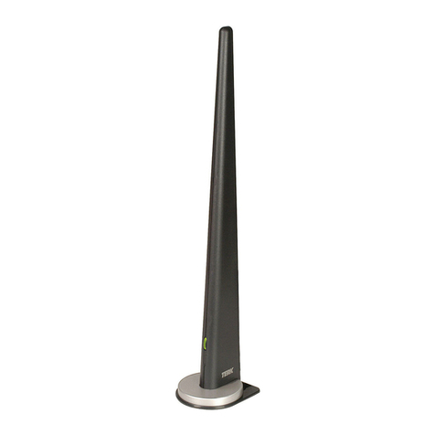
  9. TERK Technologies AM/FM Q User manual

TERK Technologies AM/FM Q User manual

Other TERK Technologies Antenna manuals
TERK Technologies PI-B User manual

TERK Technologies

TERK Technologies PI-B User manual

TERK Technologies XM5 User manual

TERK Technologies

TERK Technologies XM5 User manual

TERK Technologies AM/FM Tower Powered Indoor Antenna User manual

TERK Technologies

TERK Technologies AM/FM Tower Powered Indoor Antenna User manual

TERK Technologies RMTHINTV1A User manual

TERK Technologies

TERK Technologies RMTHINTV1A User manual

TERK Technologies Trinity Xtend User manual

TERK Technologies

TERK Technologies Trinity Xtend User manual

TERK Technologies XM5 User manual

TERK Technologies

TERK Technologies XM5 User manual

TERK Technologies Multi-Satellite Dish Antenna 1DIRECTV User manual

TERK Technologies

TERK Technologies Multi-Satellite Dish Antenna 1DIRECTV User manual

TERK Technologies AMADV-OM User manual

TERK Technologies

TERK Technologies AMADV-OM User manual

TERK Technologies AF-1 User manual

TERK Technologies

TERK Technologies AF-1 User manual

TERK Technologies SIR3 User manual

TERK Technologies

TERK Technologies SIR3 User manual

TERK Technologies TERK XM4 MM User manual

TERK Technologies

TERK Technologies TERK XM4 MM User manual

TERK Technologies HDR-I - TERK - HD Radio Antenna User manual

TERK Technologies

TERK Technologies HDR-I - TERK - HD Radio Antenna User manual

TERK Technologies Trinity Xtend User manual

TERK Technologies

TERK Technologies Trinity Xtend User manual

TERK Technologies THINTV6A QSG 01 User manual

TERK Technologies

TERK Technologies THINTV6A QSG 01 User manual

TERK Technologies AM/FM Tower Powered Indoor Antenna User manual
TERK Technologies

TERK Technologies AM/FM Tower Powered Indoor Antenna User manual
TERK Technologies TV42 User manual

TERK Technologies

TERK Technologies TV42 User manual

TERK Technologies MTVGLS User manual

TERK Technologies

TERK Technologies MTVGLS User manual

TERK Technologies Terk FM+ User manual

TERK Technologies

TERK Technologies Terk FM+ User manual

TERK Technologies FM EDGE User manual

TERK Technologies

TERK Technologies FM EDGE User manual

TERK Technologies TV44 User manual

TERK Technologies

TERK Technologies TV44 User manual
TERK Technologies xm11 User manual

TERK Technologies

TERK Technologies xm11 User manual

TERK Technologies TV5 User manual

TERK Technologies

TERK Technologies TV5 User manual

TERK Technologies AM/FM Tower Powered Indoor Antenna User manual

TERK Technologies

TERK Technologies AM/FM Tower Powered Indoor Antenna User manual

TERK Technologies FDTV2 User manual

TERK Technologies

TERK Technologies FDTV2 User manual

Popular Antenna manuals by other brands

DAVIS Windex AV 3160 installation instructions

DAVIS

DAVIS Windex AV 3160 installation instructions

Belden Hirschmann BAT-ANT-N-14G-IP23 Mounting instruction

Belden

Belden Hirschmann BAT-ANT-N-14G-IP23 Mounting instruction

Vtronix YHK Fitting instructions

Vtronix

Vtronix YHK Fitting instructions

KVH Industries TracVision 6 Technical manual

KVH Industries

KVH Industries TracVision 6 Technical manual

Leica Geosystems GS10 user manual

Leica Geosystems

Leica Geosystems GS10 user manual

Sirio Antenne Gain-Master manual

Sirio Antenne

Sirio Antenne Gain-Master manual

Sony VCA-41 Installation/connections

Sony

Sony VCA-41 Installation/connections

ZCG Y100 Series installation guide

ZCG

ZCG Y100 Series installation guide

Advantech Wireless INTREPID120 Assembly instructions

Advantech Wireless

Advantech Wireless INTREPID120 Assembly instructions

Cerio ANT-10AO installation guide

Cerio

Cerio ANT-10AO installation guide

Alfa Network APA-L01 Specifications

Alfa Network

Alfa Network APA-L01 Specifications

Naval PR-422CA Operation manual

Naval

Naval PR-422CA Operation manual

Feig Electronic ID ISC.ANTH200/200 Series manual

Feig Electronic

Feig Electronic ID ISC.ANTH200/200 Series manual

Directive Systems & Engineering DSE2324LYRMK quick start guide

Directive Systems & Engineering

Directive Systems & Engineering DSE2324LYRMK quick start guide

HP J8999A instructions

HP

HP J8999A instructions

MobilSat MSP-S Mounting instructions

MobilSat

MobilSat MSP-S Mounting instructions

Steren ANT-UHF 13 instruction manual

Steren

Steren ANT-UHF 13 instruction manual

Novatel 600-G User information

Novatel

Novatel 600-G User information

manuals.online logo
manuals.online logoBrands
  • About & Mission
  • Contact us
  • Privacy Policy
  • Terms and Conditions

Copyright 2025 Manuals.Online. All Rights Reserved.

AM/FM Q
Powered Indoor Antenna
Q
OWNER’S MANUAL
Making Connections
With Your New AM/FM Q
Radio tuners and receivers can have different connections
for your new AM/FM Q antenna. Please find the connection
that best matches your tuner or receiver and follow the
listed instructions.
FM Connections
75 Ohm oaxial:
Your TERK antenna has a Slip-On oaxial connector on
the FM lead. Simply slide the connector onto the coaxial
terminal. See Fig. 1.
75 Ohm Push-Button onnection:
If your Radio tuner or receiver has Push-Button terminals
for FM you will need to use the supplied RED 75 Ohm
matching transformer. First slide the RED 75 Ohm
matching transformer into the connector on the FM lead
of the antenna. Next slide the RED wire into the terminal
marked “FM 75 Ohm”. Lastly connect the BLA K wire into
the terminal marked “FM Ground” or “GND”. See Fig. 2.
Q
1
ANTENNA
GND AM
Fig. 1 Fig. 2 Fig. 3
AM Connections
Your TERK antenna uses a Twin Lead Bare Wire for
AM connections. If your radio tuner or receiver has a
Push-Button connection, simply slip the bare wires into
the push button connections. For a Screw Terminal
connection, wrap the bare wires around the screw
terminals and tighten. See Figs. 2/3.
Power onnection:
Plug the small end of the included power supply into the
jack located on the Slip-On oaxial connector at the end
of the FM Lead. Plug the large end of the power supply
into any working electrical outlet.
NOTE: When plugged into an electrical outlet, your TERK
antenna will remain “ON”. This is not a problem because
the A adapter uses very little power. To turn “OFF” the
power supply, it must be plugged into a switched outlet.
Some late model radio tuners and receivers come with a
switched outlet located on the back. It is safe to use this
outlet for the TERK power supply.
Q
2
Dual-Mode Operation
Your TERK antenna is designed to bring out the best in
your AM/FM receiver. It is a sophisticated, variable band-
mode, high-tech instrument that incorporates the latest
advances in antenna design and computer circuitry. The
Terk AM/FM Q antenna provides you with dual tuning
modes: Wideband Tuning and Narrowband Tuning.
AM/FM Wideband Tuning Position
To set the antenna to Wideband mode, rotate the bottom
dial clock-wise until all LED’s are RED. Wideband mode
disables the exclusive Pin-Dot Pre-Tuning feature.
Wideband allows equal “pick-up” power for all stations
on the dial. See Fig. 4.
Q
3Fig. 4
AM/FM Narrowband Tuning Position:
The Q also provides you with the ability to pick up hard-
to-get radio stations and achieve the best possible signal
with the least amount of noise with Pin-Dot Pre-Tuning.
Pin-Dot Pre-Tuning allows you to manually “fine tune” in
weaker stations.
To set the antenna to Narrowband mode and take
advantage of Pin-Dot Pre-Tuning, adjust the bottom dial
counter-clockwise to the Narrowband position. You are in
Narrowband mode when all LED’s are GREEN except for
one RED LED. You “fine tune” a station by positioning the
single RED LED like a dial on a tuner. The left-most LED
is 88MHz and the LED furthest right represents 108MHz.
Example: If the station you want to fine-tune is 95.5,
then position the red LED between the left and center
green LEDs. See Figs. 5.
Q
488 108
95.5 MHz
Fig. 5
Locating Your AM/FM Q
For Best Results
1. All antennas are affected by electromagnetic fields.
To maximize performance, position your AM/FM Q
antenna away from direct contact with receivers,
tuners, D players, TVs and computers.
Note: Antennas work best when D players, V Rs and
computers are turned off.
2. Keep the antenna away from large metal objects.
Placing the AM/FM Q near a window often provides
the best results.
3. On occasions, certain areas in your home may be
null points or dead spots where no radio signal can
be received. This may also occur in metal-frame
buildings and houses with aluminum siding. In this
case, simply move your antenna, trying different
locations, until the best reception is achieved.
4. In weak signal areas, optimum tuning is achieved
with your receiver’s scan button in the off position.
5. The Q’s AM loop antenna is the BLA K rippled section
of the antenna. For optimum AM results, position the
”AM Loop“ away from the FM portion of the antenna
so that the AM Loop is at a 90˚ angle from the FM
antenna. The AM portion of the Q is non-amplified.
See Fig. 6.
Q
5
Helpful Information
About Your AM/FM Q
Remember that no antenna can receive a radio signal
that isn’t there. When a usable radio signal is present,
your AM/FM Q will improve AM and FM reception.
Note: Generally, a practical limit to radio reception is
40-50 miles from the broadcast transmitter depending on
the terrain.
Gain ontrol Knob
Located on the back of the AM/FM Q is the gain control
knob. The gain control is the mechanism that either
increases or decreases the antenna’s amplifier intensity.
The further away you are from the radio signal, the more
you increase the gain. If you are very close to the radio
signal, signal saturation occurs. Lowering the gain will
decrease the amount of distortion. See Fig. 7.
Q
Fig. 6 Fig. 7
6
Limited Warranty
Common Questions
TERK is a registered trademark. The TERK logo is a trademark of the TERK Technologies Corp.
TERK TE HNOLOGIES ORP. (TERK) warrants this product against defects in
materials or workmanship for one year from the date of purchase. During this
warranty period, this product will be repaired or replaced, at TERK’s option,
without charge.
Please read your instructions thoroughly and use this product only as directed.
This warranty does not cover any damage due to commercial use, accident,
misuse, abuse, or negligence. This warranty is valid only in the United States of
America.
Repair or replacement as provided under this warranty is the exclusive remedy
of the consumer. TERK shall not be liable for any incidental or consequential
damages for breach of any expressed or implied warranty on this product,
except to the extent prohibited by applicable law. Any implied warranty of
merchantability or fitness for a particular purpose on this product is limited to
the duration of this warranty.
Q: My TERK antenna does not work with my boom box. What can I do?
A: You can only use a TERK antenna on a system where there is an input for an
external antenna. Some portable boom box radios do not have such an input.
Q: an I extend the wire on my FM antenna to place it on a window sill or
somewhere away from my receiver?
A: You can extend the wire with RG-59 cable and a two-way “F” connector.
These items are available at any electronics store.
Q: When I touch the antenna, it works better. How come?
A: When you touch the antenna, and your feet are touching the ground, you are
acting as a giant antenna. You can only accurately judge how the antenna is
working when you let it go.
For more information, visit www.terk.com or,
for technical support, call 1.800.942.TER (8375). 71P004