TERMET TERMAQ Series User manual

TA
1450
012-12
INSTALLATION AND OPERATION MANUAL
Instantaneous gas water heater

DEAR CUSTOMER,
Congratulations on choosing the termet product.
You have purchased a modern, economical and environment-friendly
product that complies with high EU quality standards.
Please take time to get yourself familiarised with this manual, as full
understanding of the product's functions, as well as knowledge of
manufacturer's recommendations is imperative for its smooth,
economical and safe operation.
Please keep this manual handy throughout the whole operational
lifetime of the water heater.
We hope you will be satisfied with our product.

IO-752:2018/EN 05.12.2018
1
CONTENS
1. INTRODUCTION .......................................................................................................................................................2
1.1. IMPORTANT TIPS............................................................................................................................................2
2. PRODUCT DESCRIPTION........................................................................................................................................3
2.1. Technical features.............................................................................................................................................3
2.2. Water heater construction and technical data...................................................................................................3
2.2.1. Main components of the water heater......................................................................................................3
2.2.2. Technical data...........................................................................................................................................5
2.3 Protection equipment ........................................................................................................................................5
3. WATER HEATER INSTALLATION............................................................................................................................5
3.1 Main installation regulations..............................................................................................................................6
3.1.1 Removing and installing the front cover........................................................................................................6
3.1.2 Location.........................................................................................................................................................6
3.1.3 Ventilation......................................................................................................................................................6
3.1.4 Flue gas offtake system ................................................................................................................................6
3.1.5 Gas system ...................................................................................................................................................7
3.2 Preliminary check-up operations.......................................................................................................................7
3.3 Water heater mounting......................................................................................................................................7
3.4 Connecting to the gas supply............................................................................................................................7
3.5 Connecting to the water supply.........................................................................................................................7
3.6 Connecting to a flue system..............................................................................................................................8
4WATER HEATER OPERATION................................................................................................................................8
4.1 Preparing the water heater for the first start-up................................................................................................8
4.2 Water heater starting-up ...................................................................................................................................9
4.3 Water temperature and water flow regulation...................................................................................................9
4.4 Water heater switching off...............................................................................................................................10
5ADAPTATION OF THE water HEATER TO COMBUST OTHER TYPES OF GAS................................................10
5.1 Gas consumption values.................................................................................................................................10
6KEEPING IN THE RIGHT TECHNICAL CONDITION.............................................................................................10
6.1 Heat exchanger cleaning (removing sediment and scale)..............................................................................10
6.2 Burner maintenance........................................................................................................................................11
6.3 Water filter cleaning.........................................................................................................................................11
6.4Gas filter cleaning............................................................................................................................................11
6.5 Safety system checking ..................................................................................................................................11
6.5.1 Checking the protections against flue gas outflow into the room................................................................11
6.5.2 Checking the protection against heat exchanger overheating....................................................................11
7DIAGNOSTICS ........................................................................................................................................................12
7.1 Igniting system diagnostics .............................................................................................................................12
7.2 Igniting system checking.................................................................................................................................12
7.3 Checking the coils of differentia pressure valve..............................................................................................12
8DEFECTS - CAUSES AND METHODS OF REMOVING........................................................................................13
IO-752:2018/EN 05.12.2018
2
1. INTRODUCTION
This instruction manual describes instantaneous gas
water heaters, adapted for installations with one or more
tap (eg. shower, sink etc.).
All drawings, specifications and another information
included in this instruction are based on the up-to-date
data of the product, available at the moment of issuing
this instruction.
The manufacturer reserves the right to make changes
in gas water heater design, without indicating them in
the instruction, as far as the modifications do not have
influence on the operational and technical features of
the product.
Long-term operation of the product and its reliability
most depend on proper installation and use as well as
performing the maintenance in due time and in proper
way.
1.1. IMPORTANT TIPS
Read this before any installation works or use.
•Gas appliances, that are permitted for use and
signed with symbol are safe if they are being
used appropriately and complying with specific rules
of installation and use.
•This installation guide and user’s manual is an
integral part of the water heater unit and as such it
should be kept at hand, and be studied carefully
throughout, as it contains all the necessary
information and precautions that need to be
observed to ensure the safety of installation, usage
and maintenance of this unit. In case of transferring
the appliance to another user, this manual should be
also attached.
•The installation and regulation works must be
performed by an authorised company.
•A room that the unit will be installed in must provide:
-flue conducting, through a pipe connected to an
individual flue with a proper draught,
- efficient supply - exhaust ventilation –in
accordance with this instruction manual and the
local regulations.
Non-observance of this requirements may be
unsafe for a user and may also cause the product
damage (i.e. example water system freezing).
•The unit may be assembled and started up only after
all the other construction and installation works in its
designated room are finished. It is strictly forbidden
to assemble and use the unit in rooms where
construction or other installation works are still under
way.
•Gas and water systems should be equipped with
appropriate filters, which are not included with the
unit.
•The water heater can be operated only by adults.
•Do not perform any repairs or alterations to the water
heater on your own.
•It is strictly forbidden to make any modifications that
could reduce the clearance of air-intake holes
(covering, blanking off etc.) or uptake and flue ducts
in a room and in the appliance.
•Do not keep any containers with inflammable,
aggressive or strongly corrosive chemicals close to
the water heater.
•It is forbidden to keep or dry clothes or other
inflammable objects on or nearby the appliance and
flue ducts.
•The service and maintenance operations of the
water heater can be only performed by an authorised
company.
•Effects of not - observance the instructions included
in this document by gas engineers or users are
excluded from the warranty coverage.
•After exploitation of the boiler, disassembled product
transfer to a specialized unit for utilization.
The manufacturer will not be liable for any
damage or malfunction of the product caused
by faulty installation or use, as the results of
non-observance the manufacturer instructions
and any relevant, official regulations.
Before you start up the water heater,
concerning for your safety, make sure if:
1. Permanent air supply that is necessary for
gas combustion is provided,
2. The appliance has been connected to an
individual and efficient chimney duct,
3. The gravitational ventilation duct is not
choked.
If you smell a gas:
1. Do not use electric switches likely to
cause a spark.
2. Open the door and windows.
3. Shut down the main gas valve.
4. Contact the gas emergency service.
5. If the gas escapes from an untaught valve
of a gas cylinder, shut down the valve,
disconnect the cylinder and take it outside
the building.
6. If the gas escaping from a leaky valve on
the cylinder catches fire, throw a wet
blanket on the cylinder in order to
extinguish the fire, and then pour water on
it in order to cooling down the cylinder and
make possible to turn off the valve.
In a case of breakdown:
1. Turn off the gas supplying valve.
2. Turn off the water supply if there is a risk
of flooding.
3. If there is a risk of water heater freezing,
drain out the water from it.
If you smell fumes:
1. Switch off the heater by turning off the hot
water tap or shut down the gas valve of
water heater.
2. Open the door and windows.
3. After airing the room, switch on the heater
for a while and check if the gas smell
disappeared. If not, contact the fitter or the
chimney service in order to check the
exhaust system efficiency.
IO-752:2018/EN 05.12.2018
3
2. PRODUCT DESCRIPTION
2.1.Technical features
•Electronic ignition with a ionisation flame control
•Lack of chimney draught protection and fumes
leak protection.
•Heat exchanger overheating protection.
•Proportional power regulation.
•Device adapted for water supply system from 20 to
1000 kPa (0,2 to 10,0 bar)
Gas instantaneous water heaters type GE-19-02 and
GH-19-02 are manufactured as B11BS installation type
version, what means that they are intended to be
connected to the individual flue chimney. Combustion
products are taking out of the room by means of natural
draught. The air for the combustion process is being
taken directly from the room where the water heaters
are installed. Water heaters are equipped with a
protection against draught loss in a flue pipe and
protection against fumes escape into a room.
The water heaters GE-19-02 and GH-19-02 are
equipped with the most recent technical solutions which
provide long-lasting, faultless and economic
performance and the comfort of use.
The fittings used in the water heaters ensure
proportional power regulation, which enables to get
constant temperature of outflowing water.
Activation (burner ignition) of the water heater takes
place with each opening of the tap. Shutdown takes
place after closing the tap.
One of the main advantages of the water heaters is little
water flow necessary to start up the appliance (about
3,2 l/min).
Each water heater is destined to combust only one type
of gas (for example 3B-G30) and the water heater must
be fed only with this type of gas.
The water heater’s type, the group and type of gas, as
well as the service line pressure which the water heater
was designed for, are marked on the packaging, in the
instruction manual and on the marking plate.
The water heater can be converted to another type of
gas only by an Authorized Service Center in accordance
with point 5.
2.2. Water heater construction and
technical data
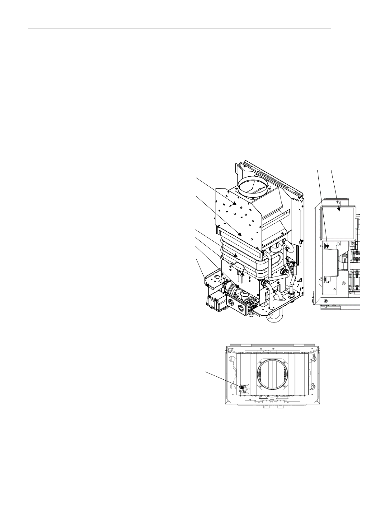
2.2.1. Main components
of the water heater
Temperature limiter as protection against overheating
of the heat exchanger
Fig. 2.2.1.1 Main components of the water heater
1 Burner
2 Electrode set
3 Water-gas fittings
4 Heat exchanger
5 Draught breaker
6 Spark generator
7 Battery compartment
8 Temperature limiter - protection against flue gas
outflow into the room
6 7
8
5
4
2
1
3
7

IO-752:2018/EN 05.12.2018
4
Fig. 2.2.1.2 Schematic diagram of the water heaters
1. Burner
2. Electrode set
2.1. Igniting electrode
2.2. Ionisation electrode
3. Water-gas fittings
3.1. Gas flow knob
3.2. Temperature selection knob
3.3. Gas filter
3.4. Water supply filter
3.5. Differential pressure valve
3.5.1.Coil I of the differential pressure valve
3.5.2.Coil II of the differential pressure valve
3.6. Regulating screw of the microswitch
3.7. Regulating screw of the little water flow
3.8. Microswitch
4. Heat exchanger
5. Spark generator
6. Battery compartment
7. Hydrogenerator
8. Temperature limiter - protection against flue gas
outflow into the room
9. Temperature limiter - protection against
the heat exchanger overheating
10. LED display
11. Cable assembly
IO-752:2018/EN 05.12.2018
5
2.2.2. Technical data
2.3 Protection equipment
•Protection against flue gas outflow into the room (case of draught loss) consists of a temperature limiter (item
8) connected in series with electric supply. This protection unit shuts down the main gas valve in the water - gas
fittings and cutting off the gas supply to the burner if the draught of the chimney duct is below 3 Pa or overpressure
occurs.
After the protection switches off the water heater, it is necessary to turn off a water tap. After about 10 minutes
(after cooling down the temperature limiter; this time depends, among others, on the room temperature), the
protection is automatically unlocked. After turning on a water tap there will flow hot water.
If activation of this protection device repeats, it is necessary to contact proper chimney sweep service
company in order to check-up the draught of a flue system.
Protection against a lack of chimney system draught must not be switched off.
The user must not make any modifications on the protection equipment.
Switching off or damaging the protection system may cause the leakage in a flue system.
•Anti-outflow protection –basing on ionization flame control - causes cutting off the gas supply to the burner by
means of electric system - in the case of flame disappearance.
•Protection against the heat exchanger overheating, i.e. the temperature limiter (item 9) actuates if the water
temperature in the heat exchanger exceeds 950C, by cutting off the voltage in the supply system, and also closing
the gas supply to the burner.
It is forbidden to make any modifications in the water heater protection systems.
3. WATER HEATER INSTALLATION
After all installation works are completed, it is necessary to check up if all gas and water connection are tight.
Diagram of the water, gas and flue –gas discharge system is presented on the Fig. 3.1.3.1
NOTE:
The wires, water and gas connection elements (filters, valves), neither flue –gas discharge elements are not included
in water heater equipment.
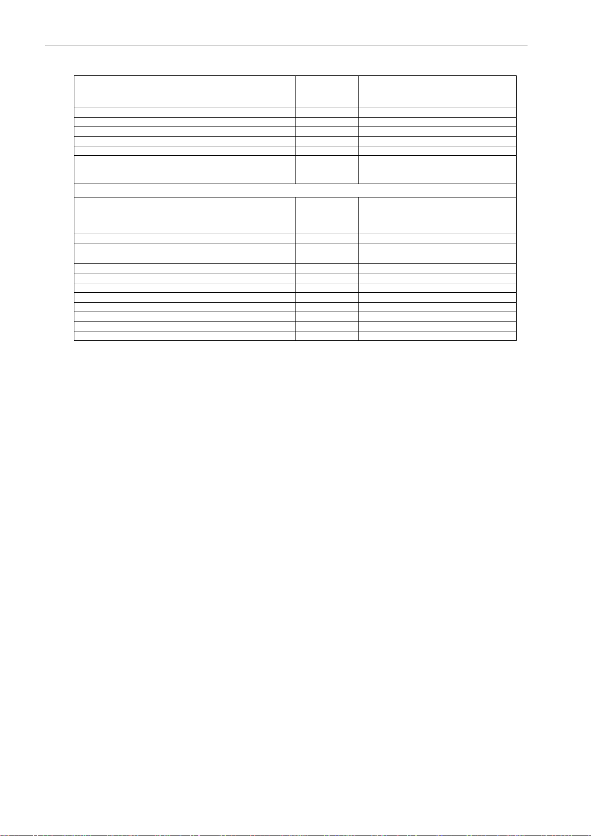
Parameter
Unit
GE-19-02
GH-19-02
Nominal input power
kW
19,2
Minimal input power
kW
7,7
Nominal heat load
kW
21,8
Minimal heat load
kW
8,8
Efficiency
%
88
Nominal gas consumption1) of a main burner, for:
Natural gas: 2H-G20
Liquefied gas: 3+-G30/G31-28÷30/37mbar
m3/h
kg/h
2,3
1,7
1) Consumption of particular types of gas is given for reference gases, in reference conditions: (150C, pressure1013 mbar) allowing for 87% of water heater efficiency
Rated gas kinetic pressure on the water heater connection
with a gas supply, for:
Natural gas: 2H-G20
Liquefied gas: 3+-G30/G31-28÷30/37mbar
kPa(mbar)
2,0 (20)
3,7 (37)
Water operating pressure
kPa(bar)
20÷1000 (0,2÷10,0)
Hot water outflow (t500C)
Hot water outflow (t250C)
dm3/min
dm3/min
3,2÷5,7
5,7÷11,5
Maximal temperature of outflow water
0C
65
Flue connection (external diameter)
mm
ø114
Overall dimensions: height / width / depth
mm
590/360/230
Hater weight
kg
9,5
Installation dimensions
mm
fig. 3.6.1
Gas connection
Inch
G 1/2
Cold water connection
Inch
G 1/2
Hot waterconnection
Inch
G 1/2
IO-752:2018/EN 05.12.2018
6
3.1 Main installation regulations
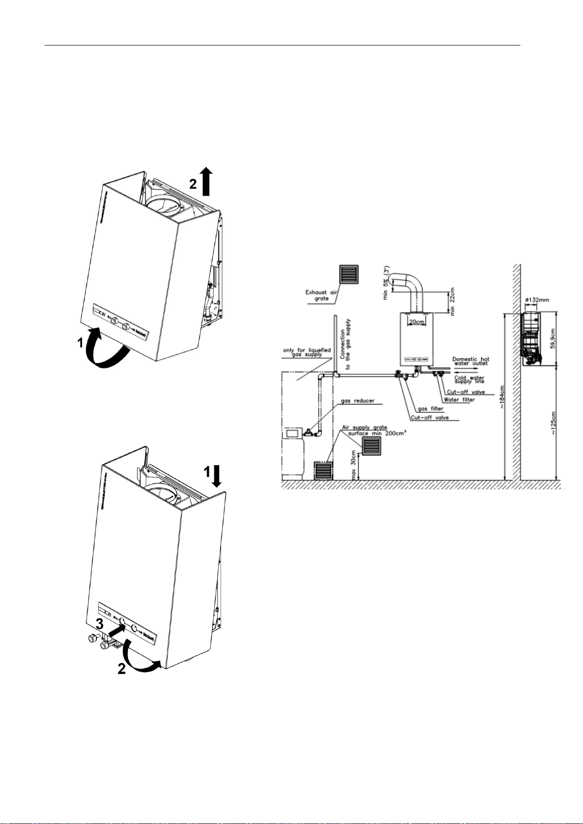
3.1.1 Removing and installing the
front cover
Removing the front cover:
1. Grab the bottom of the cover and pull it towards
you.
2. Lift the cover upwards.
3. Remove the knobs.
Installing the front cover:
1. Put the front cover on the hooks of the back
cover.
2. Place the cover so that the openings of the
panel and fittings are in the same position.
3. Mount the knobs.
3.1.2 Location
•Water heaters cannot be installed in rooms where
people stay most of the time.
•The room cubature –no less than 8 m3.
•The room height–no less than 2.2 m.
3.1.3 Ventilation
•Supply ventilation
In the room where the water heater is installed, there
should be a non-closing hole of supply ventilation, of
the surface not less than 200 cm2, whose lower edge
should be not higher than 30 cm above the floor level.
It is admissible to supply the outside air from the
adjacent rooms equipped with a non-closing hole of
supply ventilation of the surface not less than 200 cm2.
•Exhaust ventilation
In the room where the water heater is installed, there
should be a non-closing hole of exhaust ventilation
with the surface not smaller than 200 cm2, placed as
close to the ceiling as possible.
It is not allowed to use mechanical exhaust
ventilation (e.g. kitchen ventilating hood).
3.1.4 Flue gas offtake system
Water heater should be installed as close as possible to
the individual chimney duct and in a place not exposed
to frost. The cross-sections of the pipe as well as the
flue duct should remain the same along the entire length.
The flue duct should leave the appliance vertically (min.
220mm) to the first elbow. The horizontal section of the
flue duct at the lift of 5% (ca. 3o), should not exceed the
length of 2m (Fig. 3.1.3.1) The length of the flue duct,
measured from the axis of the flue duct inlet to the edge
of the duct outlet above the roof should not be less than
2m. The internal surface of the flue-gas duct should be
corrosion-resistant.
•Water heater connection to the flue gas duct must be
agreed with the proper chimney sweep company and
should meet the requirements presented on Fig.
3.1.3.1.
For the correct water heater operation, the flue gas
conducting system must provide the draught not
Fig. 3.1.3.1 Diagram of water, gas and flue –gas
conducting systems

IO-752:2018/EN 05.12.2018
7
less than 3 Pa (0.03 mbar) and not more than 15 Pa
(0.15mbar).
3.1.5 Gas system
Gas appliances should be permanently connected to
steel or copper pipes of the gas system or by means of
metal tubes.
Liquefied gas system
•Gas appliances fed with liquefied gas cannot be
installed in rooms where the floor level is situated
under the ground level.
•The cylinders should be situated in a distance not less
than 1.5 m from heat radiating surfaces (radiators,
stoves, etc.).
•The cylinders cannot be exposed to radiation of
places with open fire.
•The cylinders should be situated in vertical position,
protected against falls, beats, from children etc.
•The cylinders should be placed in a distance of at
least 1 m from devices likely to cause electric
sparkling, e.g. electricity meters.
•The room temperature where the cylinder will be
located cannot exceed +35oC.
Recommendation:
Because the one gas cylinder with the capacity of 11 kg
in the exploitation of the water heater is sufficient for a
short time, it is recommended to use a set of 11-kg
cylinders, so called battery, or a bigger cylinder with the
capacity above 11kg. Such a battery or (max. 10
cylinders) or a larger cylinder should be placed outside
the building.
3.2 Preliminary check-up
operations
Before installation, it is necessary to check if:
•the purchased water heater is adapted for combustion
the type of gas supplied from the gas mains which the
appliance will be connected to. The type of gas the
water heater has been adapted for is designated on
the packaging and the marking plate placed on the
front cover.
•the water system has been rinsed thoroughly with
water, in order to get rid of possible rust, scale, sand
or other foreign matter, which could disturb the proper
operation of the water heater (e.g. increase the
resistance of water flow in the system).
3.3 Water heater mounting
Water heater should be installed in a place not posing
significant difficulties for a service team, on a wall made
of non-flammable materials or isolated from an
inflammable wall with a plate made of non-flammable
material.
In case of building the water heater over in a furniture
system, air supply necessary for proper gas combustion
should be provided (Illus. 3.3.1).
Do not mount the water heater in the neighborhood of
appliances likely to disturb its operating (e.g. over a
cooker from which vapors rise).
Mount the water heater on the wall, on hooks
permanently fixed in it, using two rectangular notches
on the water heater back cover.
Fig. 3.3.1 Required mounting distances
3.4 Connecting to the gas supply
Fig.3.6.1 shows the connection diameters. For gas pipe,
the diameter is G3/4.
Gas water heaters not equipped with gas flow stabilizer
are adopted to be installed in the gas system equipped
with individual mean pressure reducer. Cables with a
valid certificate should be used for installation.
On the system pipe should be installed a cut off
valve and a gas filter. Installing the gas filter is
necessary for correct and long-lasting operation of
the gas unit and the burner. Filter is not included in
the installation kit.
3.5 Connecting to the water supply
Fig.3.6.1 shows the connection diameters. For water
pipe, the diameter is G1/2. On the system pipe should
be installed a cut-off valve.
Connecting the water heater to the water supply system
should be performed by means of flexible connectors or
stiff pipes. These pipes are not included in the
installation kit.
The connection to the water system should be made in
such a way that the geometry of the water heater is
maintained. Incorrect execution of the connection may
cause distortion of the water heater, which may make it
impossible to mount the knobs or lead to their blocking.
In order to stop mechanical pollution, and thus,
provide the water heater reliability and its long-term
operation, a water filter should be installed on the
supplying pipe. The filter must not cause any
resistance for a water flow and should be easy
cleaning. The filter is not included in the basic water
heater equipment.

IO-752:2018/EN 05.12.2018
8
3.6 Connecting to a flue system
Flue gases should be taken off from the water heater to an individual chimney duct, by means of a pipe with external
diameter 117 mm (GE-19-02, GH-19-02), made of the material protected against corrosion.
External diameter 117 mm
Fig. 3.6.1. Installation dimensions (mm)
4 WATER HEATER OPERATION
4.1 Preparing the water heater for
the first start-up
Before proceeding with the first start-up of the water
heater, it is necessary to:
•Fill the water system with water so as after turning on the
water taps water may flow. This ensures that the water
heater will be correctly filled with the water and it will be
operating properly.
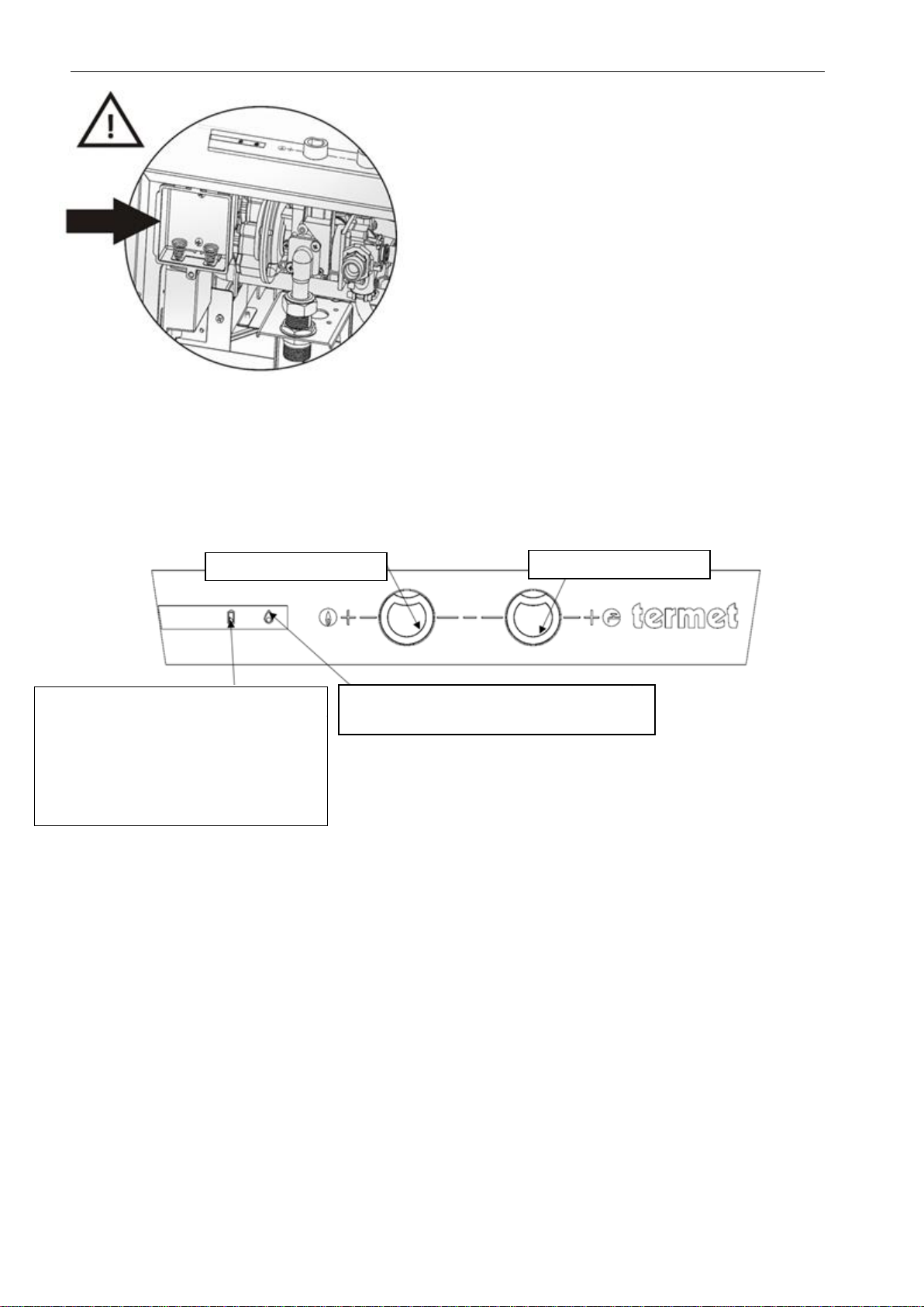
•Put on the gas flow knobs and the temperature selection
knobs –push in the knobs drawing attention on their
position in relation to the inside knobs.
•In water heaters GE-19-02
,
open the batterie compartment and insert a R20 batteries
drawing attention to its polarity. Next, close down the
compartment.
IO-752:2018/EN 05.12.2018
9
Fig. 4.1.1 Opening batterie compartment.
Batteries are not included in water heater equipment.
The producer recommends using batteries designed for
RTV equipment.
Do not regenerate the discharged batteries in any way,
do not heat them, do not throw them into a fire –risk of
explosion.
Water heaters are ready to use after installation.
4.2 Water heater starting-up
In order to start-up the water heater it is necessary to:
•Turn on the gas knob on the water heater connection
(for liquefied gas: to open the valve on the cylinder),
•Turn the gas flow knob from the “0” position into one
of the 4 positions of the thermal power of boiler
(stepwise movement of the knob). After turning on
the domestic hot water tap, electric sparkling on the
igniting burner will be heard (6 sec.). After a while
the gas will be ignited on the igniting burner and then
on the main burner.
If the knob is placed in “0” position – spark
generator produces a spark during 70 seconds, gas
on the igniting burner and main burner will not be
ignited.
During the first start-up, the system and the gas
fittings should be vented. Because of this, the first
start-up may last longer than 20 seconds.
Water heater is ready to operate.
After opening the hot water tap, automatic gas ignition
takes place on the burner segment, and at the rest of
segments - after a while hot water will flow out.
After turning off the hot water tap, the gas supply to the
burner will be cut off.
4.3 Water temperature and water
flow regulation
Water heaters are equipped with modern gas-water
fittings ensuring proportional power regulation, what
enables to receive constant water temperature. The
fittings are equipped with a water flow limiter with a
smooth regulation. If the water temperature selection
knob (Illus. 4.3.1) is turned in its extreme right position,
little water flow will be received (i.e. 5,7 dm3/min) with
the highest temperature (gas flow knob in its extreme
left position), smaller flow will be received by decreasing
the flow by means of water tap.
If the temperature selection knob is turned into its
extreme left position, a big water flow will be received
(i.e. 11,5 dm3/min) with the lowest temperature (gas flow
knob position as above).
After setting the temperature selection knob in its
transitional positions, water temperature growths will
change inversely proportional to the water flow.
Decreasing the water flow in the water heater, by means
of the temperature selection knob, from the 11.5 to 5.7
dm3/min, water temperature growth changes from 25º to
50ºC. Water temperature (in any operation positions of
the water flow regulator) can be regulated by means of
gas flow knob
Fig. 4.3.1. Regulation and function elements
LED display –yellow diode
Continues light –water heater is operating
LED display –red diode
Flashing light –signaling not enough
voltage of supply
TERMAQ ELECTRONIC ECO –
discharged batteries
TERMAQ AQUA-POWER ECO –
too little water flow
Gas flow knob
Water flow knob

IO-752:2018/EN 05.12.2018
10
4.4 Water heater switching off
Switching off the water heater is made by turning the gas flow knob into its extreme right (position “0”) (Fig. 4.3.1)
In case of an anticipated long break in the water heater operation, the gas valve on the water heater connection or the
valve on the liquefied gas cylinder, should be shut down.
If in a room, where the water heater has been installed, temperature may decrease below 0ºC, it is necessary to drain
the water heater out of water.
In order to do this, cut off the cold water supply, then undone the nut on the pipe supplying the water into the water
unit and turn on the hot water tap.
5 ADAPTATION OF THE WATER HEATER TO COMBUST OTHER
TYPES OF GAS
The water heater supplied by the manufacturer is designed for combustion of the gas indicated on the rating plate.
If it is necessary to supply the device with other gas than the one for which it was factory adapted, it is necessary to
check for which gas it can be adapted.
Adaptation of the water heater to another type of gas can only be done by the AUTORIZED COMPANY SERVICE.
This activity is not included in the scope of warranty repairs.
Gases to which the water heater can be adapted are given on the rating plate in the category designation of the device:
II2ELsLw3PB/P - which means that they are designed to combust gases from two categories
Gas category
Gas group
Gas type
second
natural gas
G20
GZ-50
third
liquid gas
G30
B
G31
C
5.1 CO emissions
Gas type
CO emissions [ppm]1)
2E-G20
58 ± 5
3P-G30
48 ± 4
3B-G30
48 ± 4
3P/B-G31
490 ± 155
1)CO concentration for maximum gas pressure Pmax.
5.2 Gas consumption values
Gas type
Range of kinetic gas
pressure in the gas
network
kPa (mbar)
GE-19-02, GH-19-02
Gas consumption1)
(dm3/min)
pmin
pnom
pmax
from
to
Natural: 2E-G20
(GZ –50)
1,6
(16)
2,0
(20)
2,5
(25)
35,5
40,5
Liquid: 3PB/P-G30/G31
(B i C)
3,0
(30)
3,7
(37)
4,2
(42)
11
12
1) Consumption of particular types of gas is given for reference gases, in reference conditions (150C, pressure 1013 mbar) allowing for 88% of water
heater efficiency
6 KEEPING IN THE RIGHT
TECHNICAL CONDITION
In order to ensure the appropriate and long-lasting
operation of the water heater, there should be
performed periodical maintenance operations.
Inspections and maintenance operations should be
performed by an authorized company,
at least once a year. The scope of the maintenance
operations is presented below.
Before starting the maintenance operations, the gas
and water supply should be cut off, and then the water
should be drain out from the appliance. Before
cleaning the water heater, first disassembly the burner
and then follow the same way with the heat
exchanger.Heat exchanger cleaning (removing
sediment and scale)
To ensure full gas combustion and retain maximum
heat exchange efficiency in the water heater, it is
recommended to keep the segments of the heat
exchanger in permanent cleanliness.
Cleaning the heat exchanger out of sediments requires
it to be disassembled from the water heater and rinsed
with a strong water stream.
If there is a need of removing the boiler scale from the
ducts of the heat exchanger, this operation should be
IO-752:2018/EN 05.12.2018
11
performed with the use of agents available on market,
according to the recommendations of agent producer.
The scale can also be removed by means of 10-20%
acetic acid, by keeping it in the heat exchanger for about
3 hours. After this operation, the exchanger should be
thoroughly rinsed with clean water.
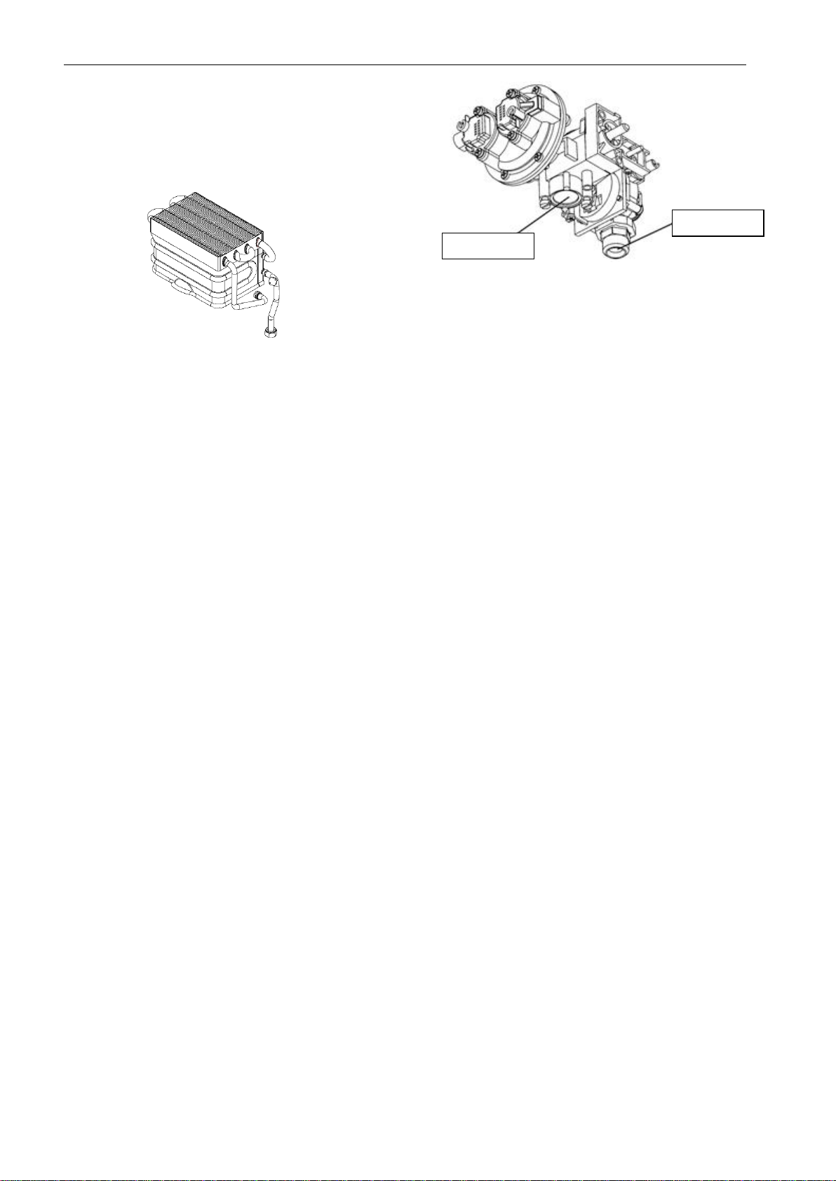
Fig. 6.1.1. Heat exchanger
Do not use the wire brushes, or another brushes with
hard bristle
6.1 Burner maintenance
During the burner maintenance the plates on the
segments should be cleaned by means of soft brush
(not the wire one). Pay attention whether the plates or
segments were not damaged.
6.2 Water filter cleaning
In case of notifying too small stream of water flowing out
from the water heater and difficulty in igniting the burner,
the water supply valve and the gas valve on the
appliance connection should be shut down. Check up
and clean the water filter on the water pipes on the
appliance connection. Sometimes may occur choking of
the internal filter in the water assembly. Then fittings
should be taken out from the water heater. The filter
should be dismounted, cleaned and mounted again
(Fig.5.4.1).
6.3 Gas filter cleaning
In case of finding too poor stream of gas flowing out of
the main burner and difficulties in burner ignition, the
valve on the water supply line and gas valve on the
appliance connection with the gas supplying system
should be shut down. Check up and clean the gas filter
situated on the appliance connection with the gas
supplying system. Occasionally may appear the
situation of choking inside filter of gas –water fittings. In
such case the fittings should be taken out the water
heater. Then take out the filter, clean it and assembly
again. (Fig. 5.4.1)
Fig.6.4.1 Water-gas fittings
6.4 Safety system checking
During every inspection correctness of the protection
systems operation should be checked as well and
tightness of the gas fittings as well.
6.4.1 Checking the protections against
flue gas outflow into the room
Temperature limiter (Illus. 2.2.1.1 item 10) - protection
against gas outflow into the room, is set for the
temperature 85±3°C (GE-19-02, GH-19-02).
In order to verify the correctness of the limiter setting,
the following operations should be performed:
•prepare a metal vessel with a thermometer,
•fill the vessel with a liquid,
•take the limiter out of the holder (unscrew the
screws), put it into a vessel submerging in the liquid
only the metal cap
•heat the liquid up to the temperature of 82°C (GE-
19-02, GH-19-02) –in such temperature the limiter
should not actuate,
•heat the liquid up to 88°C (GE-19-02, GH-19-02) –
in such temperature the limiter should actuate.
A properly operating limiter should disconnect electric
contacts in the temperature range from 82°C to 88°C
(GE-19-02, GH-19-02).
6.4.2 Checking the protection against heat
exchanger overheating
Temperature limiter (Fig. 2.2.1.1 item 11) - protection
against exceeding the upper limit of water temperature
–is set for the temperature 75±3°C (GE-19-02, GH-19-
02). In order to verify the correctness of the limiter
setting, operations as above should be performed.
A properly operating limiter should disconnect electric
contacts in the temperature range from 72°C to 78°C
(GE-19-02, GH-19-02).
During every next re-assembly of the water and gas
system, new seals should be used.
The actions mentioned in section 6 are not covered
by warranty repairs.
water filter
gas filter

IO-752:2018/EN 05.12.2018
12
7 DIAGNOSTICS
During and after the process of production, water heater
is subjected to a whole range of partial and complex
inspections.
In spite of this, during the water heater operation, some
disturbances –that are not caused by the producer –
may occur.
To make easier diagnostics of possible incorrectness in
the water heater operation, in table below essential
information has been collected. Using this information
allows eliminating some unjustified operations during
the water heater disassembly, and thus makes the time
of repair shorter.
Before beginning the water heater repair, it should
be checked if:
•water heater is adapted for the gas currently in use,
•gas pressure is at least minimal,
•negative pressure in chimney duct is within the
range 3 –15 Pa (0.03 - 0.15 mbar).
•battery voltage is adequate
(in TERMAQ ELECTRONIC water heater type )
7.1 Igniting system diagnostics
After turning on the water tap, water flowing through the
water heater should initiate the process of burner
igniting, which stages are presented below:
•clenching/short-circuit/ of the microswitch
connectors, fig. 2.2.1.3 item 3.6,
•sparkling between igniting electrode item 2.1, and
burner segment item.1,
•voltage occurrence on coil I, item 3.5.1 –valve I in the
differential valve opens (valve I in release state is
closed),
•gas ignition on one of the burner segment item 1 –
ionisation current occurrence detected by the
control electrode item.2.2,
•voltage occurrence in coil II item 3.5.2 –valve II in
the differential pressure valve closes (valve II in
release position is open),
•opening the main gas valve caused by pressure
difference over and under the diaphragm in the
differential pressure valve item 3.5,
•gas ignition on the whole burner item 1.
7.2 Igniting system checking
In the case of incorrect ignition, it is recommended to
check the ignition system, according to following
instructions:
1. Check the correctness of electric connections,
2. Connect a voltmeter to the „-” pole:
- In TERMAQ ELECTRONIC ECO water heaters - spring in
battery compartment item 6,
- In TERMAQ AQUA-POWER ECO water heaters –
hydrogenerator’ s wire (white, item 7),
3. Connect a voltmeter to the „+” pole:
- In TERMAQ ELECTRONIC ECO water heaters –metal plate in
battery compartment item 6,
- In TERMAQ AQUA-POWER ECO water heaters –
hydrogenerator’ s wire (red, item 7),
4. Measure the voltage:
- In TERMAQ ELECTRONIC ECO water heaters –the battery
voltage -1,5VDC
- In TERMAQ AQUA-POWER ECO water heaters –the
hydrogenerator’s voltage hydrogenerator’ s at resistance
load 10and at the flow 3l/min - 1,31,6VDC
5. Measure the supply voltage after loading with the
operating ignition system (correct system
operation at the voltage of 0.9-1.5VDC),
6. Check the voltage on the protection against flue
gas outflow into the room item 8 (voltage like on
battery),
7. Check the voltage on the protection against heat
exchanger overheating item 9 (voltage like on
battery),
8. Check the voltage on terminal 9 of the spark
generator, item 5 (voltage like on battery),
9. Close the microswitch connectors item 3.6.
Shorted connectors should cause sparkling
between igniting electrode item 2.1 and burner
segment item 1,
•check the voltage on coil terminals I, item 3.5.1
(correct operation of the system at voltage 0.9-
1.5V),
•after detecting the ionisation current by the
control electrode (after flame appearance),
check the voltage on the clamps of coil II, item
3.5.2 (correct operation of the system at
voltage 0.9-1.5V).
7.3 Checking the coils of
differentia pressure valve
Inspection of possible defects on the electric coils of the
differential pressure valve may be performed by
checking the resistance of the coils.
Method of taking the resistance of the coils:
•take off the muffs from the coils,
•one of the ohmmeter wire connect to the body of
the differential pressure valve,
•the other wire connect to one, and then to the next
muff of the inspected coils, every time taking the
value of the resistance.
Correct resistance values:
Coil I - 39Ω±20%
Coil II - 58Ω±20%
IO-752:2018/EN 05.12.2018
13
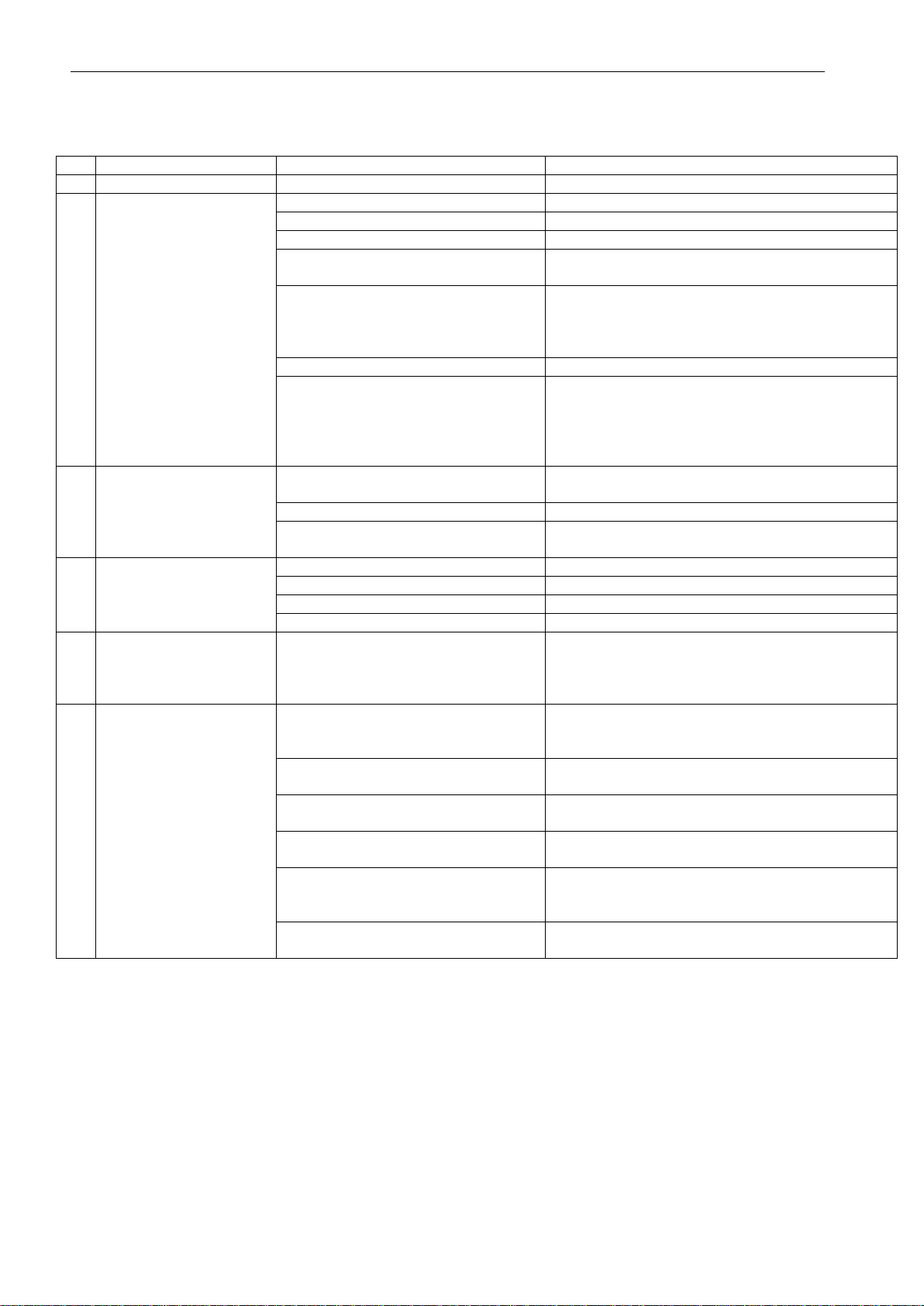
8 DEFECTS - CAUSES AND METHODS OF REMOVING
No.
Symptoms
Causes
Action
1
2
3
4
1.
No spark (no ignition
during water taking)
Electrode wire is disconnected
Correct the connection
Damaged electrode
Check - replace
Spark generator damaged
Check - replace
Dead battery or damaged
hydrogenerator
Check - replace
Microswitch wrongly regulated
Regulate the microswitch by means of screwing
the screw on microswitch lever. Pay attention if
after regulating do not appear sparkling with no
water flow
Water filter clogged (limited flow)
Remove pollutions
Elements in the water-gas fittings
damaged
Water diaphragm damaged
Control system mechanism of valve
head damaged
Replace fittings or damaged elements
2.
Igniting burner does not
ignite from the spark
No gas supply (damaged electrode)
Open the cut-off valve supplying the gas into the
water heater
Vented gas system
Vent the system
Dead battery or damaged
hydrogenerator
Replace
3.
Flame does not spread
throughout the whole
burner
Control electrode wire is disconnected
Correct the connection
Damaged control electrode
Check - replace
Damaged spark generator
Check - replace
Damaged differential pressure valve
Check - replace
4.
Trials of ignition at no
water flow
Microswitch wrongly regulated
Regulate the microswitch by means of screwing
the screw on microswitch lever. Pay attention if
after regulating do not appear delayed ignition
(sparking) during starting-up the water heater
5
Water heater does not
heat water enough
Poor flame on the burner
Check the gas pressure in gas supply network
Check the setting of the gas flow stabiliser
according to p. 5.4
Polluted burner
Remove pollution from the welts and nozzles of
the burner
Polluted radiator in the heat
exchanger
Remove pollution from the radiator fins
Remove the boiler scale
Incorrect gas composition
Check if the main burner, igniting burner and the
fittings are adapted for the gas currently in use
Excessive water flow
Check the small water flow –if water flow exceeds
5,7dm3/min, it is recommended to correct it by
means of regulating screw
Damaged elements of the water-gas
fittings
Replace fittings or damaged elements
IO-752:2018/EN 05.12.2018
14
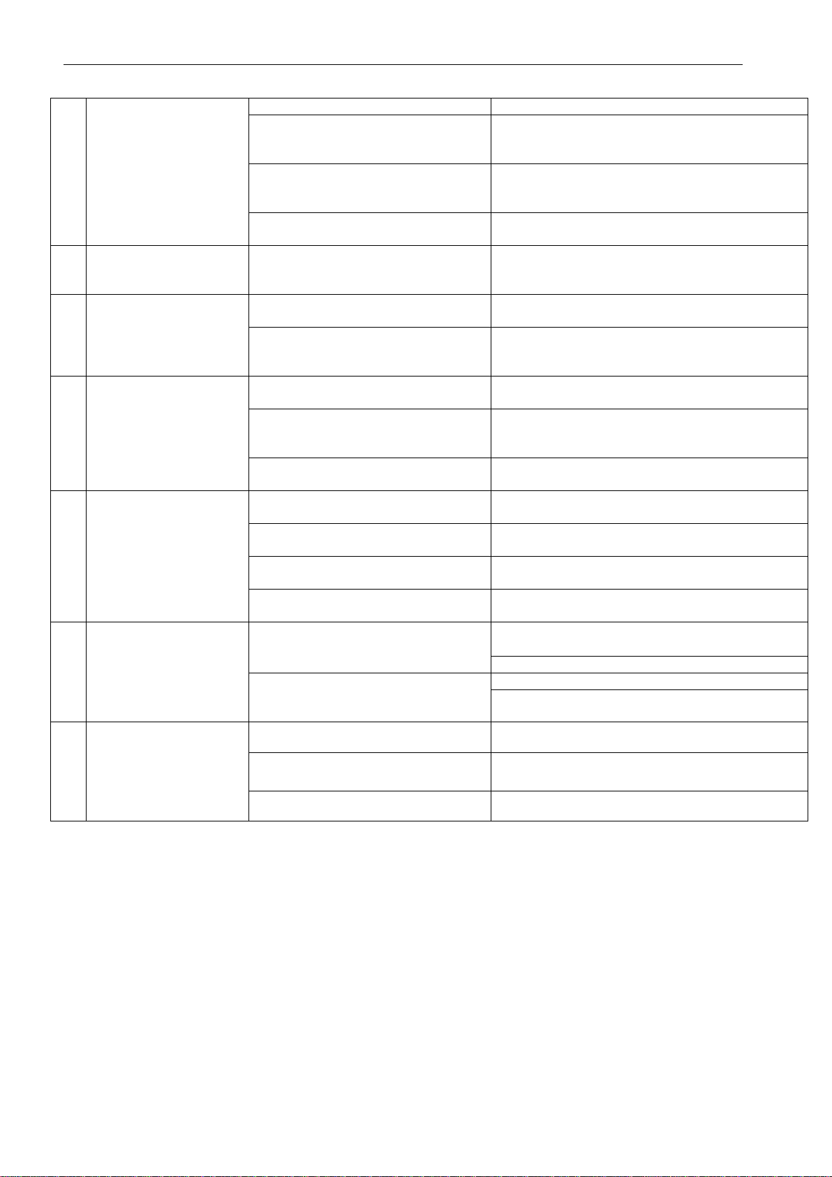
6.
Water heater overheats
water
Gas flow stabiliser incorrectly set
Regulate the stabiliser, acc. to p. 5.5
Incorrect gas composition
Check if the main burner, igniting burner and
water-gas fittings are adapted for the gas
currently in use
Too little water flow
Check the small water flow –if water flow
exceeds 5,7dm3/min, it is recommended to
correct it by means of regulating screw
Control system mechanism of valve
head is mechanically damaged
Replace damaged elements
7.
Water heater does not
to stop operating after
turning off the water flow
Elements of water-gas fittings
are mechanicallydamaged
Replace fittings or damaged elements
8.
Explosive burner ignition
Too small flame on the igniting
segment
Pipe of igniting burner is choked –clean it up or,
if necessary, replace
In water-gas fittings: gas flowcanalto
igniting segment is choked
Damaged differential valve
Replace fittings or differential pressure valve
9.
Leakage occurring in gas
system of the water
heater
Gasket ring on the inlet to water-gas
fittings is damaged
Replace gasket with a new one
One of the gaskets on the outlet from
water-gas fittings or on the inlet to
burner is damaged
Replace gasket with a new one
Water-gas fittings is mechanically
damaged
Replace fittings or damaged elements
10.
Leakage occurring in
water system of the water
heater
Gasket on the inlet to water-gas
fittings is damaged
Replace gasket with a new one
Gasket on the outlet from water-gas
fittings is damaged
Replace gasket with a new one
One of the gaskets on heat
exchanger connections is damaged
Replace gasket with a new one
Water-gas fittings is mechanically
damaged
Replace fittings or damaged elements
11.
Water heater switches off
during its operating
(during taking the water)
Protection against flue gas inflow into
the room actuates
Check the limiter –if damaged, replace
Check if vacuum in the chimney duct is correct
Protection against exceeding the
upper limit of the water temperature
actuates
Check the limiter –if damaged, replace
Water heater overheats water –action as above
12
Heat exchanger fins
get dirtyin a short time
Wrong chimney draught
Check the chimney ducts
Yellow flame
Check the gas type
Polluted burner (wrong combustion)
Clean the burner

IO-752:2018/EN 05.12.2018
Długa 13, 58-160 Świebodzice,
Infoline +48 74 856 08 01, +48 74 854 68 90
http:// www.termet.com.pl
export@termet.com.pl
[email protected]om.pl
This manual suits for next models
2
Table of contents
Other TERMET Water Heater manuals


Popular Water Heater manuals by other brands


Venus
Venus Domestic VDH 100 user manual

Rinnai
Rinnai REU-KM3237FFUD-E Installation and user manual

Raypak
Raypak FlexGas Hi Delta H 302CD-2342CD Supplemental Installation and Operating Instructions

Quick
Quick B3 Installation and use manual

A.O. Smith
A.O. Smith Water Heater user manual

Eternal
Eternal GU32DV Operator's manual

COSMOGAS
COSMOGAS AGUADENS Installation, operating and maintenance manual

Vaillant
Vaillant VPS R 100/1 M Operating and installation instructions

RED-RING
RED-RING 7000 series Installation & user's instructions

Mex
Mex CUBE 35E instruction manual

Emerson
Emerson insinkerator F-H3N1 Installation, care & use

Philips
Philips AWH1615/51 user manual