Terra tdx441 User manual

1
DVB-S/S2 to DVB-T/DVB-C transmodulators
tdx441, tdx481, tdq441, tdq481
EN
Vers. 1.01
This product complies with the relevant clauses of the European Directive 2002/96/EC. The unit must be recycled
or discarded according to applicable local and national regulations.
Equipment intended for indoor usage only.
This product is in accordance to following norms of EU: EMC norm EN50083-2, safety norm EN IEC62368-1, RoHS norm EN50581.
This product is in accordance with Custom Union Technical Regulations: “Electromagnetic compatibility of technical
equipment“ CU TR 020/2011, “On safety of low-voltage equipment“ CU TR 004/2011.
This product is in accordance with safety standard AS/NZS 60065 and EMC standards of Australia.
1. Product description
The devices are transmodulators with 8 DVB-S/S2 input channels and 8 DVB-T (tdx481), 4 DVB-T (tdx441), 8 DVB-C
(tdq481), 4 DVB-C (tdq441) output channels. The devices are designed for digital transmodulation with Transport Stream
Processing of TV or Radio programs issued from FTA (Free to air) or encrypted digital reception. Devices lter services,
modify SI (Service Information), generate NIT (Network Information table), LCN (Local Channel Number), can remultiplex
services from any input to any output. All of the congurations can be changed by using the Web Interface.
tdx441 – quad transmodulator - with eight DVB-S/S2 input channels and four DVB-T output channels.
tdx481 – octal transmodulator - with eight DVB-S/S2 input channels and eight DVB-T output channels.
tdq441 – quad transmodulator - with eight DVB-S/S2 input channels and four DVB-C output channels.
tdq481 – octal transmodulator - with eight DVB-S/S2 input channels and eight DVB-C output channels.
Transmodulators can be used as stand alone devices.
The product is intended for indoor usage only.
2. Safety instructions
Installation of the transmodulator must be done according IEC60728-11 and national safety standards.
Any repairs must be made by skilled personnel.
Avoid placing the transmodulator next to heat sources such as central heating components or in areas of high humidity.
Keep the transmodulator away from naked ames.
If the transmodulator has been kept in cold conditions for a long time, bringing it into a warm environment may cause
condensation, so allow it to warm up for no less than 2 hours before plugging into the mains.
Ventilation should not be impeded by covering the transmodulator, such as newspapers, table-cloths, curtains etc.
Mount the transmodulator in a vertical position only. If installing in a 19” rack system additional forced air cooling fans
may be required (see table "Technical specications" - operating temperature range).
Always allow 10 cm of free space from the top, front and bottom of the unit to enable any heat to be dissipated.
Manual in .pdf
2
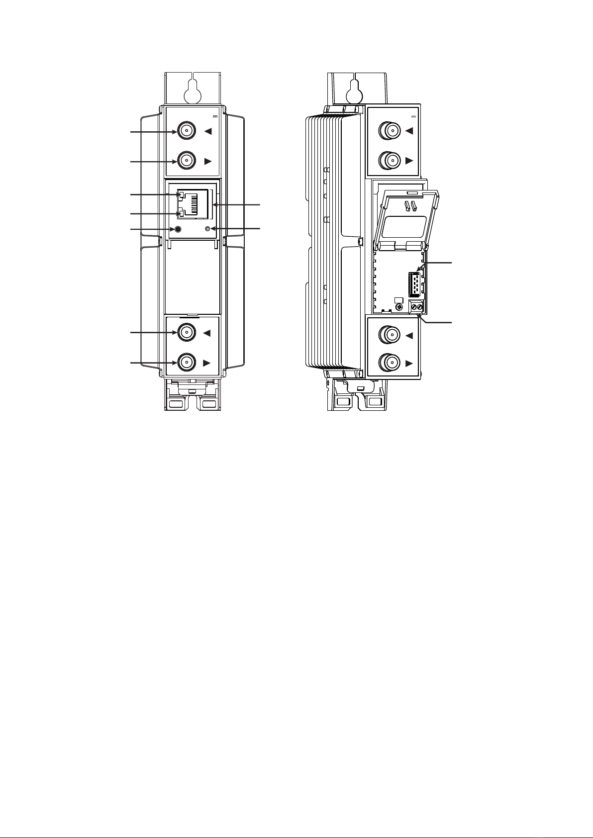
3. External view
Figure 1. External view of the transmodulator
1 - ◄ - RF input of SAT IF signal, DC output for LNB. F socket.
2 - ► - RF output (input signal loop-through). F socket.
3- ETHERNET - control Ethernet interface. RJ45 socket.
4- ACTIVITY (yellow) indicator of the control Ethernet interface.
5- LINK (green) indicator of the control Ethernet interface.
6- RESET - reset and default IP button.
Press button for more than three seconds to set default IP address of the control Ethernet interface.
Ethernet led indicators "activity" [4] and "link" [5] will start to toggle to inform, that the reset IP
address request has been accepted. Device will be restarted with default IP address.
To restore all parameters to default values (including password), keep pressing the button for
additional 4 seconds. The green (link) indicator will start blinking after that time indicating, that a
“restore defaults” command has been accepted. Now the button can be released. Yellow (activity)
indicator will light on while resetting parameters. After that device will restart with all default values.
7- STATUS - device status LED indicator.
Green light indicates that module operates normally.
Red light indicates device errors and user attention is needed.
8 - ◄ - RF input (output signal loop-through). F socket.
9 - ►- RF output. F socket.
10 - Power distribution bus connector.
11 - +12 V DC powering input. Screw terminal.
DC OUT 13/18V
0.5 A max
DC IN 12V
-
-
+
+
tdx441
RESET
ETHERNET
TERRA
1
2
4
5
3
6
8
9
DC IN 12V
-
-
+
+
10
11
tdx441
STATUS
7
DC OUT 13/18V
0.5 A max
3
4. Installation instructions
Read the safety instruction rst.
All settings can be changed using the web browser via control Ethernet interface.
Disconnect power supply unit from the mains before making any changes in the connections of the module. Fasten the
module on DIN RAIL or individual holder.
Connect all necessary RF, powering and control cables. Shielded Ethernet cable is recommended.
Connect the 75 Wload to the unused RF output F sockets.
Connect power supply in to the mains.
Within 30-40 seconds of powering the module will run in normal operation mode.
Comments of the front panel indicators:
the LINK [5] green indicator is on when the link with the control Ethernet interface is established. Indicator is o when
there is no link.
the ACTIVITY [4] indicator blinks, if communication via the control Ethernet interface is active.
Package contents
1. Transmodulator............................................................. 1 pcs.
2. Spacer .......................................................................... 1 pcs.
3. 75 W terminator ............................................................. 1 pcs.
4. Bridge F quick to F quick .............................................. 1 pcs.
5. User manual ................................................................ 1 pcs.
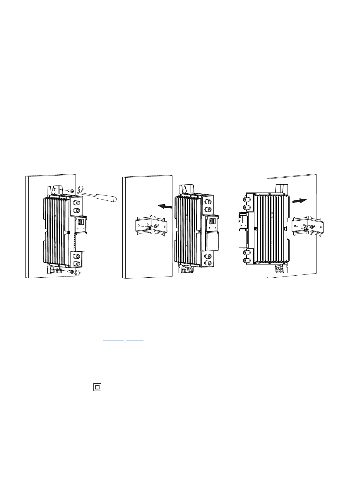
5. MOUNTING
The module or mounting bracket must be xed with steel screws Ø 3.5-4 mm. The screws are not included in a package.
Mounting bracket on DIN rail should be connected to main potential equalization bus.
Mounting on a wall by screws Mounting on a bracket (ordering number 01960)
Requirements for power supply unit (PSU)
Recommended power supplies UP410S, UP413.
It is allowed to use an external PSU that meets the next requirements:
• Output voltage +12 V ± 0.5 V
• Ripple at single and/or double mains frequency < 10 mV p-p
• Ripple & noise < 100 mV p-p
• Short circuit protection
• Double insulated (marked )
• Meet EN 55022 class B conducted emissions requirements, measuring with grounded load
Perpendicular to the wall Parallel to the wall
Figure 2. Mounting of the transmodulator

4
1. 2.
Mounting on DIN rail
Figure 5. Mounting or removing to/from
DIN rail of plastic spacers (supplied).
Figure 3. Mounting to DIN rail
Figure 4. Mounting from DIN rail
DC IN 12V
-
-
+
+
TERRA
ETHERNET
tdx481
DC IN 12V
-
-
+
+
TERRA
ETHERNET
DC IN 12V
-
-
+
+
TERRA
ETHERNET
tdx481 tdx481
RESET STATUS RESET STATUS RESET STATUS
5
[1]
[2]
[3]
6. Operating
6.1 Initial conguration
All modules leave the factory with this control over Ethernet interface IP address: 192.168.1.10. In order to avoid conicts
with other IP addresses, it is necessary to perform an initial conguration in the local mode. Subsequently, it will be possible
to access the module via local area network (LAN), either to change the conguration or to check the operating status.
The modules leave the factory with the following control over Ethernet interface TCP/IP conguration:
IP address of the module: 192.168.1.10
Subnet mask: 255.255.255.0
Default Gateway: 192.168.1.1
To access each module, use a personal computer (PC) equipped with an Ethernet card and
RJ-45 cable (CAT-5E or CAT-6). The IP address of the PC/MAC must be congured within
the following range: 192.168.1.2 - 192.168.1.254 (do not use 192.168.1.10, since this is the
IP address of the module to be congured). To start the conguration of the module, open
your web browser and type in the following direction: http://192.168.1.10. The login prompt
will appear on the screen (see Figure 6).
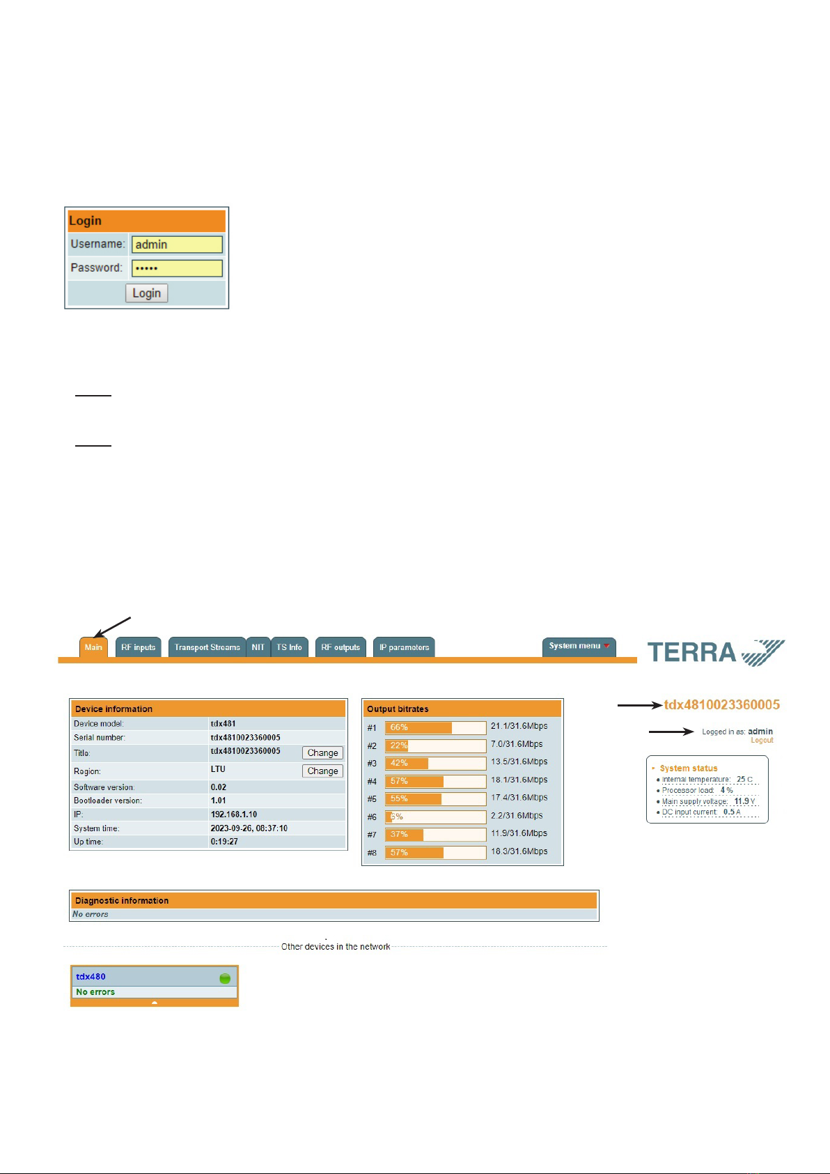
Figure 6. Login window
Access to the module is protected by user name and password. The default user name and password is admin. Enter
the user name and password and click on "Login" button.
NOTE: the default password - admin - can (and must) be changed as explained in the section 6.11.5 "User management".
During initial conguration you need to change the default control interface TCP/IP conguration as explained in the section
6.8 "IP settings".
NOTE: If you are using Internet Explorer Web browser, supported versions are version 10 or higher.
Control interface IP address reset to default procedure: press the "RESET" [6] button for more than 3 seconds. When the
LINK [5] indicator will start blinking, release it. After this operation the control interface IP address will be set to 192.168.1.10,
for more information see section 6.8 “IP settings”.
6.2 General conguration
Initial Web interface screen
The rst screen that appears when the module accessed is the "Main" window, which gives general information on the
device.
Figure 7. General information screen
In the top of each conguration screen you will see a main menu tabs [1]. Using it, you can switch between the dierent
conguration menu. The tab highlighted in yellow shows which menu is active at a given moment. The "System menu" tab
contains several submenu items. Common elements for all screens are module title [2] and login information strings [3].
Pressing on the "Logout" string you can logout from module control.
6
Device information table
This shows the following data of the module:
“Device model”: a model of the module.
“Serial number”: serial number of the module.
“Title”: the user may assign a title to the device for easier management. Press the button “Change” to modify it. This title
will be written at [2] place. Also, it will be visible in other devices, and by computers in network devices (if PC supports SSDP).
“Region”: the device supports several preinstalled regions. The RF channel list depends on which region is selected. The
region can be changed without restarting the device. Just select the needed region by pressing the “Change” button in “the
Device information” table. Additional regions can be installed under request. Contact our distributors for such possibility.
“Software version”: module software version number.
“Bootloader version”: module’s rmware bootloader version.
“IP”: the IP address which is currently assigned to the module.
“System time”: current time, synchronized from the TDT table of the input stream or NTP server. Local time oset can be
selected in the System menu/Date,Time.
“Up time”: time passed from the last power-up or restart of the module.
Output bitrates table
It displays the output bitrate status of each channel in real time, Horizontal bar shows the percentage of used available
bandwidth in the channel. The 1st number right to the bar shows the actual bitrate in Mbps. The next number shows the
maximum allowed bitrate in the channel and it depends on modulation parameters. Ensure that the actual bitrate would not
reach more than 95% of the available bandwidth. Otherwise, bitrate overow may occur.
System status table
It represents the following parameters at real time:
● Internal temperature - in degrees of Celsius
● Processor load - in percents
● Main supply voltage - module power voltage in Volts
● DC input current - module current consumption in Amperes
Other device in the network
If there are any modules in the network their status and diagnostic information will be displayed as it is in Figure 7 "General
information screen". If modules status is red press the down arrow and diagnostic errors will be displayed. Make sure, that
Ethernet router is congured properly to pass SSDP packets (239.255.255.250:1900 and 239.255.255.246:7900). Also make
sure that all modules are connected to the same Ethernet network.
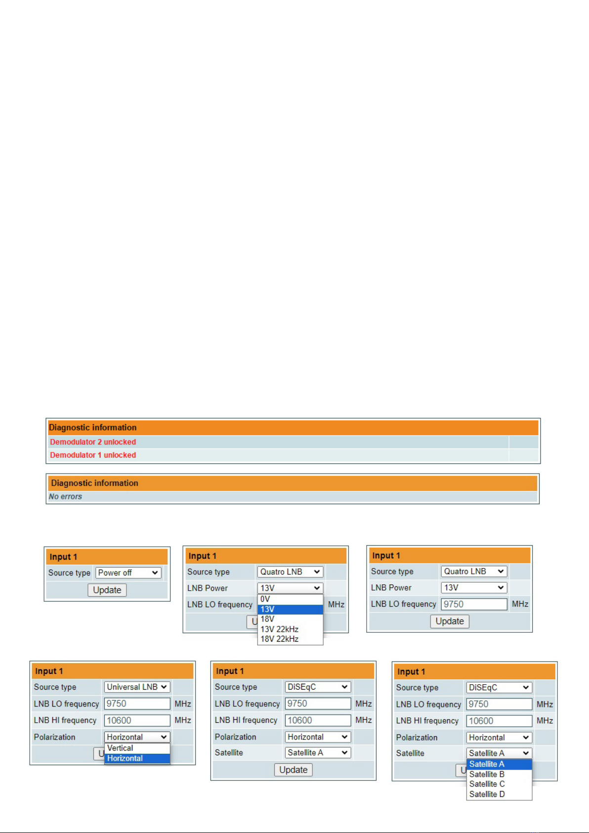
Diagnostic information table
It displays all module errors and comments (if possible) how to eliminate them.
Figure 8. Diagnostic information tables with errors and without errors
6.3 RF inputs
Figure 9. Input type selection
6
The Figure 9 “Input type selection” table consists of the following parameters:
“Source type” - the LNB types, there are several:
• Power o
No power for external equipment (for example in case using multiswitch in static mode).
•Universal LNB
“LNB LO frequency” - the LNB local oscillator lower frequency in megahertz. Use 9750 MHz for the universal LNB.
“LNB HI frequency” - the LNB local oscillator upper frequency in megahertz. Use 10600 MHz for the universal LNB.
“Polarization” - the polarization of converter. Can be “Horizontal” or “Vertical”.
Power supply voltage of the LNB is chosen according to the selected polarization – 18 V Horizontal, 13 V Vertical;
the 22 kHz is set depending on given “LNB HI frequency” “LNB LO frequency” and “Input frequency” parameters.
For example:
LNB input frequency range, MHz 10700 – 11700 11700 – 12750
LNB local oscillator frequency, MHz Lo = 9750 Hi = 10600
Downconverted input IF range, MHz 950 – 1950 1100 – 2150
Tone -22 kHz
•Quatro LNB
“LNB Power” - power supply of the converter – can be set to “0”, “13V”, “18V”, “13V/22kHz”, “18V/22kHz”.
“LNB LO frequency” - LNB local oscillator frequency in MHz.
•DiSEqC
“LNB LO frequency” - the LNB local oscillator lower frequency in megahertz. Use 9750 MHz for the universal LNB.
“LNB HI frequency” - the LNB local oscillator upper frequency in megahertz. Use 10600 MHz for the universal LNB.
“Polarization” - the polarization of converter. Can be “Horizontal” or “Vertical”.
“Satellite” - can be set to “Satellite A”, “Satellite B”, “Satellite C”, “Satellite D”.
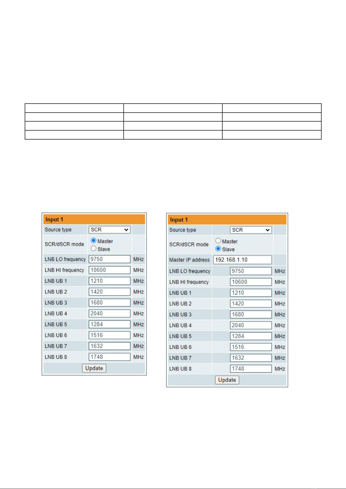
Figure 10. Input source types “SCR”
• SCR (EN50494)
“SCR” - rst select source type as shown in Figure 10, then select “SCR/dSCR mode“ Master or Slave (Master for
module which has direct connection to Unicable multiswitch or LNB and Slave for modules connected by loop through).
If Slave was selected, additionally type the IP address of Master module. All the modules in the SCR/dSCR group must
be in the same Ethernet network.
Next select “SAT input”, “User band”, type “Input frequency”, “Symbol rate”, press “Update” button (see Figure 12).
You can change UB frequencies manually if need.
7
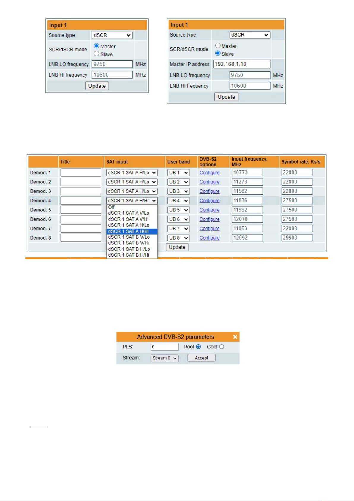
Figure 11. Input source types “dSCR”
• dSCR (EN50607)
“dSCR” - similar to “SCR” mode, just the total UB, used UB and UB frequencies module receive from connected
dSCR multiswitch or LNB.
Figure 12. Demodulator settings table
“Title” - eld is intended for assigning the name for input transponder for easier channels management.
“SAT input“ - a parameter that can switch demodulator on/o or select necessary satellite and sub band in SCR/
dSCR modes.
“User band” - parameter used in SCR/dSCR mode. UB number and its frequency according connected SCR/dSCR
multiswitch or LNB.
“DVB-S2 options” - for advanced “DVB-S2 options”, press “Congure” link and “Advanced DVB-S2 parameters”
will be displayed (see Figure 12.1).
Figure 12.1 DVB-S2 advanced parameters
“PLS” - Physical Layer Scrambling used in DVB-S2 as a way to improve data integrity. A number called the “scrambling
sequence index” is used by the modulator as a master key to generate the uplink signal. This same number must be
known by the receiver so that demodulation would be possible.
PLS mode - “Root“ or “Gold“.
“Stream” - parameter needed for multistream transponders.
NOTE: If advanced parameters is not needed make sure to leave them as shown in Figure 12.
“Input frequency“ - parameter is a frequency of transponder in MHz.
“Symbol rate“ - parameter is a symbol rate of transponder in kSym/s.
8
9
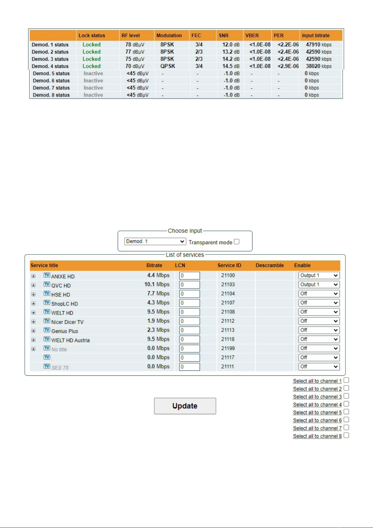
Input status table
Figure 13. Input status table
“Lock status” - shows tuner/demodulator input state. `Locked’ - signal is received and demodulated. `Unlocked’ -
signal is not demodulated. `Inactive’ - input channel is powered o.
RF level” - RF signal level at the module input. Level indication - approximate.
“Modulation” - modulation scheme of the input signal.
“FEC” - forward error correction.
“SNR” - RF signal/noise ratio at the input of module.
“VBER” - Viterbi bit error ratio.
“PER” - ratio of the MPEG2 transport error packets to the whole number of packets.
“Input bitrate” - bitrate of the input signal.
6.4. Transport Streams
One input channel at a time can be congured in this page. Select proper channel from the list at “Choose input“
combobox. A list of services in the selected channel will appear (see Figure 14 "List of services").
Figure 14. List of services
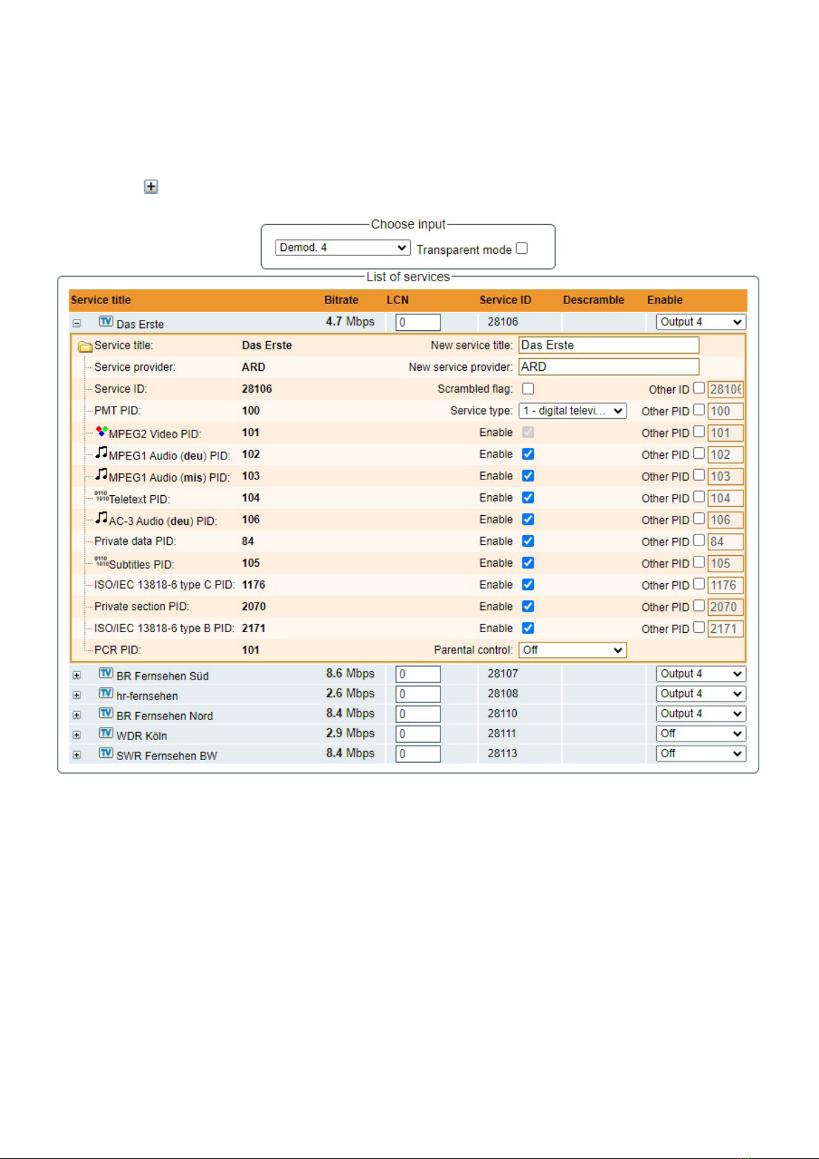
Figure 15. Service details
“Service title“ and “Service provider“ can be edited (multilanguage character support). “Scrambled ag“ will be
inserted into SDT (Service Description Table). Unchecking this checkbox will not descramble the content. It only
carries information about the scrambling status of the service.
BISS scrambled services have a BISS key input eld “BISS Code”. Enter the BISS code (12 or 16 characters)
in hex format.
“Parental control”: this selection enables ability to restrict certain content viewable by the user. For example, parental
control eld is set to “Less than 6 years”, than all content with maturity rating above 6 years old will be ltered out.
Individual streams can be disabled as well. PID number can be remapped manually by selecting checkbox “Other
PID”. Keep in mind that PID must be unique, otherwise PID remapping is done automatically.
Press onto “Update“ button to save changes and execute.
10
“List of services“ table shows a list of available services. Icon before the service name indicates service type. Bitrate
of each service is measured in real time. Services that currently are not running will be displayed as grayed. They can
be selected and will be outputted normally when the services starts running. „LCN“ eld is a Logical Channel Number.
Every service can have a „channel number“ and TV will sort channels according to it. Just ensure, that all services
in all channels have dierent numbers. Value “0” means, that LCN for that service is not used at all and TV will sort
these channels according to it’s own rules.
Services can be passed to any output number, independing on the input demodulator number.
BISS scrambled services have a checkbox for descrambling.
Press onto sign and service information will be extended (see Figure 15 “Service details”).
11
NOTE: If transparent mode is selected, all services of transponder will be passed to the output, including original PAT, SDT,
PMT, EIT, CAT, NIT tables. All changes that were made to these tables (new titles, LCN) will be disregarded. No more than
95% of output bandwidth usage is recommended, otherwise bitrate overow might occur.
6.5. NIT
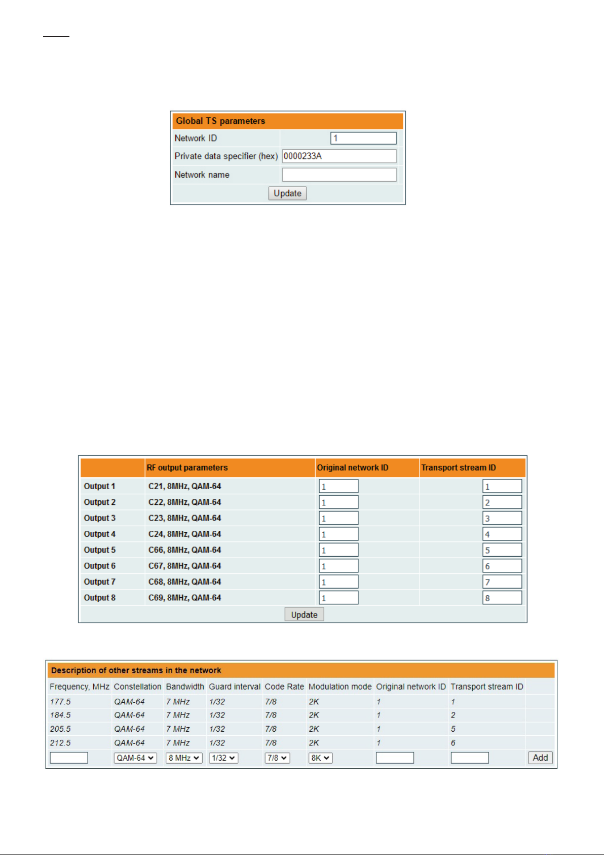
Several tables related to NIT generation exist in this section. Figure 16 "Global TS parameters" describes following TS
parameters:
Figure 16. Global TS parameters
“Network ID”: is unique number within the geographical region dened by the “country code”. For a cable network usually
this is a single country code plus 0x2000 (8192). If there are more connected modules in the network, they must have the
same Network ID.
Proper value depending on your country and operator can be found here:
http://www.dvbservices.com/identiers/network_id?page=1
“Private data specier (in hex format)”: can be inserted in the NIT table for proper LCN description. This value is described
in TS 101162 specication. NorDig standard requires 00 00 00 29 value, UK should use 00 00 23 3A value.
Other options can be found here:
http://www.dvbservices.com/identiers/private_data_spec_id?page=1
The parameter will not be inserted into NIT if value is set to zero.
“Network name“ is the name of the network.
The 2nd table in the page describes Transport stream ID and Original network ID of each channel (see Figure 17). Each
stream in a network must have unique ID, called “Transport stream ID“. An Original_Network_ID is dened as the “unique
identier of a network”. It can be linked to NetworkID or used value from this location:
http://www.dvbservices.com/identiers/original_network_id?page=1
Figure 17. Transport stream and original network IDs
Figure 18. Description of other streams in the network

12
Every channel in the network must be described in NIT. Otherwise TV automatic channel tuning function will not nd all
channels. All other modules in the network will be monitored via standard SSDP protocol. NIT tables will be regenerated if
any change is detected in other modulators with the same Network ID. Make sure, that Ethernet router is congured properly
to pass SSDP packets (239.255.255.250:1900 and 239.255.255.246:7900). Also make sure that control ports of all modules
are connected to the same Ethernet network.
NOTE: If in the RF network exists transponders that are generated by old TERRA transmodulators/modulators, the
frequencies and modulation parameters must be lled manually (Figure 18).
6.6. TS info
Figure 19. TS info
This menu window will help you to easily assign and track LCN numbers of dierent services and also allows
displaying RF channels bandwidth usage.
“Choose outputs“ - select which RF channel outputs should be displayed.
“Service title” - the list of services which are assigned to the RF output channel.
“Input source” - demodulator which is used to receive and demodulate the RF signal. This demodulator number
shows which service is demodulated by which demodulator.
“Service ID” - unique service identication number.
“LCN” - Logical Channel Number which is assigned to the service.

6.7. RF outputs
Transmodulator has one (tdx441, tdq441) or two (tdx481, tdq481) independent groups of four adjacent channels.
Figure 20. DVB-T output parameters (tdx481)
“Output frequency“ parameter can be entered manually or selected as a channel from combobox. Channels that can be
selected from the list depend on which region is selected. If you need any other frequency – select “Manual” and type the
needed frequency. Frequency step is 0.1 MHz. “Enable“ checkbox will enable channel to the output. Global attenuator can
be entered up to 15 dB. Also there is individual precise attenuator up to 2.5 dB in step of 0.5 dB.
Press “Update“ to change settings. In case, if any modulation parameter was changed, both channels will be restarted
with new settings. Exception is “Attenuator“, changes in this parameter will not restart the modulator.
Figure 21. DVB-C output parameters (tdq481)
Figure 21 shows tdq481 DVB-C output settings. In case of tdq441, count of output channels will be 4. The step of
RF channels can be selected to one of these values: 7.0, 7.5, 8.0, 8.3, 8.5 MHz. Actual bandwidth of each channel
depends on the symbol rate, and can be calculated as SR x 1.15 (1.15 here is roll o factor of 15%). Symbol rates
of all channels must be the same, from the range of 3500..7200 kSym/s.
Output channel enumeration depends on the region selected from the main page. However, it’s allowed to enter
any frequency you want in a range of 100..858 MHz (for tdq441, tdq481).
Only the rst output frequency/channel of the group can be entered by the user. Other frequencies will be calculated
automatically according to the selected step/bandwidth.
13

14
6.8 IP settings
All device IP settings can be congured here – "IP address", "Subnet mask",
"Gateway", "DNS" (Domain Name System), see Figure 22. “WEB port” number
can be changed. Default is 80. You must restart the device for the port change
to take eect. All other IP parameters will be updated immediately after pressing
“Update“ button and redirected to new location.
NOTE: IP address can be reset to default (192.168.1.10) by pressing
"RESET" button (Fig.1, pos.6) for at least 3 seconds. Ethernet led indicators
"activity" [4] and "link" [5] will start to toggle to inform, that the reset IP address
request has been accepted. Device will be restarted with default IP address.
To restore all parameters to default values (including password), keep pressing
the button for additional 4 seconds. The green (link) indicator will start blinking
after that time indicating, that a “restore defaults” command has been accepted.
Now the button can be released. Yellow (activity) indicator will light on while
resetting parameters. Device will restart with all default values after that.
Figure 22. IP settings table
6.9 E-mail-settings
The device can send e-mail reports if errors were detected. SMTP
protocol is used for that. Figure 23 “E-mail settings table” shows
parameters related to this feature. “Enable e-mail error report”
checkbox enables error monitoring. All errors within “timeout”
period will be gathered, and send to the e-mail address, provided
in “Receiver e-mail address” input box. Comma separated e-mail
addresses can be used to send report to multiple addresses. The
timer will be started as soon, as the rst error is detected, and
stopped when e-mail is sent. The timer will be restarted again if
a new error will appear.
“Sender e-mail address” can be used as authentication in the
SMTP server side.
SSL (SMTPS) protocol is not supported.
Figure 23. E-mail-settings table
6.10 SNMP settings
Figure 24 "SNMP settings table" is located in “IP parameters” tab.
The description of the SNMP conguration parameters:
“Read Community” - community name acts as a password that is shared
by multiple SNMP agents and one or more SNMP managers. “Read
Community” password is used for read-only access to the modules
parameters.
“Write Community” - is the password used for read-write access to the
modules parameters.
“Enable TRAP” - SNMP traps are alerts generated by agents on a
managed device. Check this box to enable TRAP generation. The module
generates traps when the diagnostic message occurs.
“TRAP Community” - is the password used for accessing of TRAPS.
“Host IP #1”,”Host IP #2”, ”Host IP #3” - IP addresses of hosts with SNMP
managers, where TRAPS will be send.
Figure 24. SNMP settings table
15
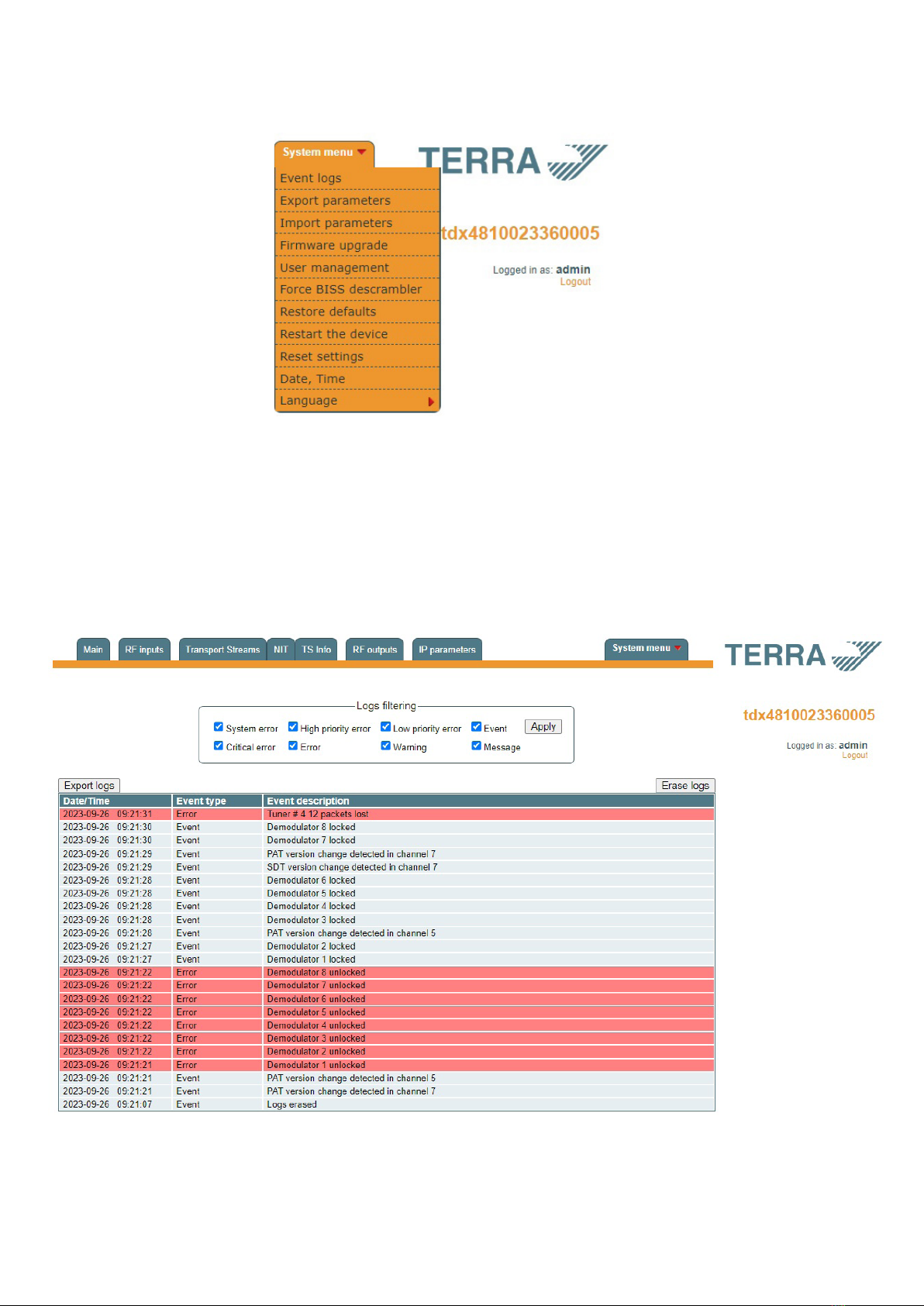
6.11 System menu
This menu tab contains following submenu items: “Event logs”, “Export parameters”, “Import parameters”, “Firmware
upgrade”, “User management”, “Force BISS descrambler“, “Restore defaults“, “Reset the device“, "Date,Time",
“Language”. Mouse over to show the list of this submenu.
Figure 25. System menu
6.11.1 Event logs
Various important events, errors, warnings will be logged into the system Figure 26 "Event logs". Each record has
an event type, which can be used to lter particular messages. Just select checkboxes in the “Logs ltering“ table and
press “apply“. Other messages will be hidden.
“Erase logs“ button will erase all logs from the system.
“Export logs” button forms the le (log.html) which will be downloaded to PC.
Each record has a log time when the event appeared. Refer to 6.11.8 "Date, Time" settings for instructions how
to congure time settings.
Figure 26. Event logs

6.11.2 Export parameters
All settings of transmodulator can be exported for backup or copying to another device. Press “Export parameters” and
“parameters.xml” le will be downloaded to PC. This le can be imported only to the same type of device.
6.11.3 Import parameters
Exported parameters can be imported back to the device. Press onto “Click to select le” button (see Figure 27 “Import
parameters”) to select exported le.
Figure 27. Import parameters
Press “Upload” button to send the le to the device. It will take several seconds to update all parameters after le upload.
After that, device will function with new conguration. No restart is required.
6.11.4 Firmware upgrade
Device rmware can be upgraded via web browser. Press the “Click to select le” button and select rmware binary le. If
valid le was selected, a version number of new rmware will be displayed. Otherwise an error message will appear. Press
the “Upload” button to upload new rmware to the device. Upload progress bar will appear and may take several seconds to
upload, depending on the size of a le and a network connection speed. A message will be displayed asking to restart the
device when the le was sent to the device. New rmware will be programmed into the device only after restart. It may take
additional minute or more to ash new program. Device will start up with a new rmware and continue to operate with previous
parameters. Additional new rmware features (if any) may need to setup additionally to take eect.
Avoid power supply interruption when a programming process is going on.
Device has possibility to load software revision history and check availability for new software release. Click the “Check
online” link. If computer (not device!) has internet access, it will show a list of all software releases with links to binary les.
Binary le can be downloaded and saved to computer (see Figure 28 “Firmware upgrade”). After that, use the rmware
upgrade method as described above.
Figure 28. Firmware upgrade
6.11.5 User management
User may change a password here. Length of the password is up to 16 symbols. Type current password and double enter
new password to change it.
If logged in user has admin role, new users can be added (see Figure 29 “User management”).
Figure 29. User management
16
17
Enter it’s username, password, select a role and press “Add“ button.
Only administrator (user with a role „admin“) may manage other users.
NOTE: By giving your personal password or user access account for another person, you take full responsibility for all
module settings modications made by that person or anyone else they may give the password to.
6.11.6. Restore defaults
All parameters will be restored back to factory defaults after conrmation. The exception – IP address and users – these
parameters will be unchanged. To restore IP address and system password to system defaults, see “RESET“ button at
section 3 "External view", pos.6.
Several seconds can take to restore all parameters, so be patient.
6.11.7. Restart the device
Device will be restarted after conrmation to do it. This is an alternative to pressing a “RESET“ button when the device
is operating.
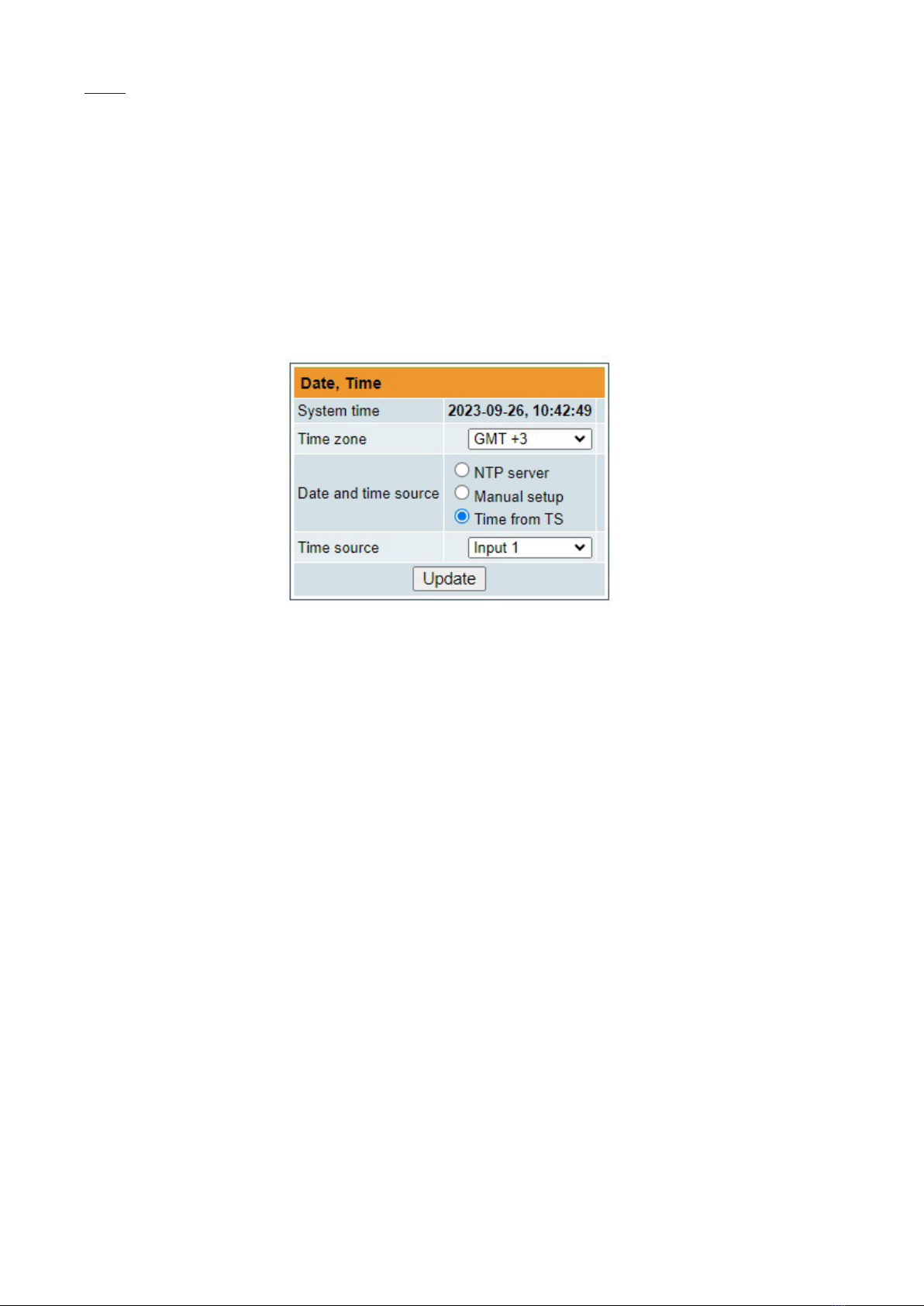
6.11.8. Date, Time
System time can be congured manually or taken from NTP server (only if module can access NTP server). Also there is
an option to select the time source from TS as shown in the Figure 30.
Figure 30. “Date, Time” settings table
6.11.9. Language
Device control panel supports several preinstalled languages. A change of language requires system restart. Note,
that all previously logged records will remain in previous language.
Additional languages can be installed under request. Contact our distributors for such possibility.
6.11.10. Force BISS descrambler
If enabled, this checkbox allows BISS input eld for all services. See Transport Streams (Figure 15.) menu where
you can insert the BISS code.

Type tdx481 tdx441 tdq481 tdq441
Sections input/output 8/8 8/4 8/8 8/4
RF input RF input count 1
frequency range 950-2150 MHz
level / impedance 55-95 dBµV / 75 W
return loss ≥ 10 dB
loop through frequency 950-2150 MHz / ≤ 1.5 dB
range/loss
LNB powering/control 0/13/18 V & 22 kHz, 500 mA total, DiSEqC 1.0, EN50494, EN50607
standard DVB-S/S2*
modulation QPSK, 8PSK,
APSK 8/16/32
symbol rate 2 ÷ 45 Ms/s
RF output standard DVB-T DVB-C
modulation QPSK, QAM16, QAM64 QAM16, QAM32, QAM64, QAM128, QAM256
frequency range 170 - 230 MHz, 470-862 MHz 96-862 MHz
channel allocation, adjac. 4 +4 4 4 +4 4
level / impedance 90 ± 2 dBµV / 75 W
TS bit rate < 31 Mbit/s < 53 Mbit/s
MER ≥ 35 dB ≥ 40 dB
channel bandwidth 7 MHz / 8 MHz 4...8.3 MHz
guard interval 1/4, 1/8, 1/16, 1/32 -
code rate 1/2, 2/3, 3/4, 5/6, 7/8 -
symbol rate - 3.5 ÷ 7.2 Ms/s
return loss ≥ 10 dB
roll off - 15 %
transmission mode 2K -
total output level 0 ÷ -15.0 dB by 1 dB step
adjustment range
loop through frequency 45-862 MHz / ≤ 2.5 dB
range/loss
Management port standard IEE802.3 10/100 Base T
Supply voltage 12 V ± 1 V
Current consumption 1.2 A 1.0 A 1.2 A 1.0 A
without external load
Current consumption 2.2 A 2.0 A 2.2 A 2.0 A
with maximum external load
Operating temperature range 0o ÷ +35o C
Dimensions/Weight (packed) 63x198x112 mm / 1.26 kg
7. Technical specications
pr.
pr.
pr.
pr.
pr.
pr.
pr.
pr.
pr.
pr.
pr.
pr.
pr. software control
Draugystes str. 22, LT-51256 Kaunas, Lithuania, tel.: +370 37
-
31 34 44, fax: +370 37
-
31 35 55
* supports physical layer scrambling (PLS) and multiple input streams (MIS)
** without external DC feeding
This manual suits for next models
3
Table of contents
Other Terra Media Converter manuals


Popular Media Converter manuals by other brands

The Telios Alliance
The Telios Alliance Z/IPStream R/1 Quick start setup guide

LDT
LDT LS-DEC-USA Operating instruction

Allen-Bradley
Allen-Bradley 931S-F1C2D-DC installation instructions

MaxLux
MaxLux МХ0053 quick start guide

IFM
IFM E43406 operating instructions

Speaka Professional
Speaka Professional SP-5965732 operating instructions


