VideoLogix Proteus-IV User manual

Proteus-IV
User Manual

TABLE OF CONTENTS
GENERAL OVERVIEW...................................................................................................................................................................................................................4
COMMUNICATION .........................................................................................................................................................................................................................4
COM PORTS ......................................................................................................................................................................................................................................4
COM PORTS:PINOUTS.......................................................................................................................................................................................................................4
COM PORTS:BAUD RATE ..................................................................................................................................................................................................................5
COM PORTS:DEVICE TYPES ..............................................................................................................................................................................................................5
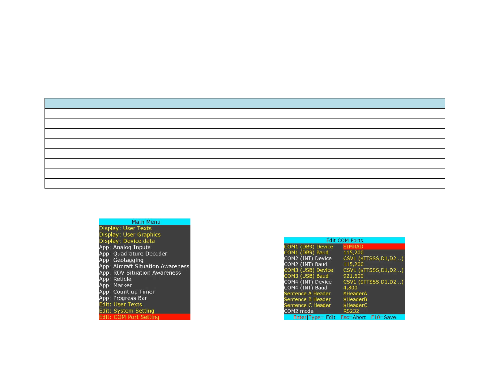
COM PORTS:CONFIGURATION ..........................................................................................................................................................................................................5
CSV FORMATS ..................................................................................................................................................................................................................................6
INTERFACE TO PC...............................................................................................................................................................................................................................6
INTERFACE TO GPS MODEM................................................................................................................................................................................................................6
VIDEO INPUT & OUTPUT..............................................................................................................................................................................................................7
VIDEO FRAME RATES.........................................................................................................................................................................................................................8
VIDEO DELAY....................................................................................................................................................................................................................................8
IRIG INPUT........................................................................................................................................................................................................................................8
SOFTWARE WIZARDS ...................................................................................................................................................................................................................9
INSERT TEXT......................................................................................................................................................................................................................................9
INSERT GRAPHICS ............................................................................................................................................................................................................................11
INSERT VARIABLES FROM CSV SENTENCE ........................................................................................................................................................................................13
INSERT DATA FROM RS232 COMMAND.............................................................................................................................................................................................13
INSERT GPS DATA ............................................................................................................................................................................................................................16
INSERT NMEA DATA.........................................................................................................................................................................................................................18
INSERT TIME,DATE (IRIG,GPS,RTC,ATC)........................................................................................................................................................................................18
INSERT AEROSPACE DATA................................................................................................................................................................................................................19
INSERT ANALOG DATA.....................................................................................................................................................................................................................20
INSERT COUNTERS...........................................................................................................................................................................................................................22
INSERT AIRCRAFT SITUATION AWARENESS.....................................................................................................................................................................................26
INSERT ROV SITUATION AWARENESS..............................................................................................................................................................................................28
INSERT RETICLE...............................................................................................................................................................................................................................30
INSERT VIDEO MARKER....................................................................................................................................................................................................................32
INSERT COUNT UP TIMER .................................................................................................................................................................................................................35
INSERT PROGRESS BARS &SLIDERS .................................................................................................................................................................................................36
WRITE GEOTAG DATA......................................................................................................................................................................................................................38
READ GEOTAG DATA .......................................................................................................................................................................................................................38
PROTEUS COMMANDS................................................................................................................................................................................................................41
TRANSMIT A COMMAND SCRIPT......................................................................................................................................................................................................41
PROTEUS REGISTERS .................................................................................................................................................................................................................42

SPECIFICATIONS..........................................................................................................................................................................................................................49
MAXIMUM INPUT VOLTAGE.............................................................................................................................................................................................................49
INPUT CONNECTOR ..........................................................................................................................................................................................................................49
MAXIMUM TEMPERATURE...............................................................................................................................................................................................................49
WEIGHT &DIMENSION ....................................................................................................................................................................................................................49
FRONT PANEL LED ...........................................................................................................................................................................................................................49
PCB DIMENSION..............................................................................................................................................................................................................................50
APPENDIX A - KEYBOARD .........................................................................................................................................................................................................51
PS2 KEYBOARD COMMANDS............................................................................................................................................................................................................51
KEYBOARD SHORT CUT ...................................................................................................................................................................................................................51
APPENDIX B –DOWNLOAD CUSTOM FONTS.......................................................................................................................................................................52
DOWNLOAD USER FONTS.................................................................................................................................................................................................................52
CREATE YOUR OWN FONTS..............................................................................................................................................................................................................52
APPENDIX C –INSTALL MEMTOOL........................................................................................................................................................................................53
INSTALL MEMTOOL..........................................................................................................................................................................................................................53
CONFIGURE MEMTOOL ....................................................................................................................................................................................................................54
APPENDIX D –DOWNLOAD CPU FIRMWARE ......................................................................................................................................................................55
FIRMWARE UPGRADE.......................................................................................................................................................................................................................55
APPENDIX F –DOWNLOAD FPGA FIRMWARE....................................................................................................................................................................57
FPGA UPGRADE ..............................................................................................................................................................................................................................57
APPENDIX G –ANALOG INPUT SENSOR CALIBRATION ..................................................................................................................................................58
EXAMPLE 1.....................................................................................................................................................................................................................................58
EXAMPLE 2......................................................................................................................................................................................................................................59
EXAMPLE 3......................................................................................................................................................................................................................................60
EXAMPLE 4......................................................................................................................................................................................................................................62
EXAMPLE 5......................................................................................................................................................................................................................................63
APPENDIX H –WIFI SETTING ...................................................................................................................................................................................................64
WIFI ...............................................................................................................................................................................................................................................64
APPENDIX I –TERMINAL BLOCKS..........................................................................................................................................................................................65
HOW TO INSERT WIRE INTO TERMINAL BLOCKS ...............................................................................................................................................................................65

GENERAL OVERVIEW
Video Overlay is a method by which computer-generated images are superimposed on video. Properly transformed images appear as if they are an
integral part of the scene without impeding the video of the actual environment. Proteus provides professional, scientific and industrial users with the
capability to overlay crisp and clear texts, graphics and telemetry generated information into an incoming HD & SD video in real time. Proteus accepts
video in HD-SDI, HDMI, Y/C and Composite. It generally, does not need to be connected to a computer for normal operation.
COMMUNICATION
COM PORTS
Proteus provides 4 x serial ports (COM1 thru COM4) for communication with the external devices:
COM PORT
Alternative 1
Alternative 2
Alternative 3
COM1
RS232 (Rear Panel DB9)
-
-
COM2
RS232 (Internal TB: J45)
RS422 (Internal TB: J50, J61)
WiFi
COM3*
RS232 (Rear Panel USB)
RS232 (Internal TB: J46)
COM4
RS232 (Internal TB: J52)
-
-
COM PORTS:PINOUTS
COM PORT
Connector
Modes
Isolated
Pin assignments
COM1
DB9
RS232
Yes
DB9:
2=RX, 3=TX, 5=GND
COM2
Internal
RS232
RS422
-
J45:
J50:
J61:
1=5V, 2=TX, 3=RX, 4=GND
1=RX+, 2=RX-, 3=GND
1=TX-, 2=TX+, 3=GND
COM3
USB
RS232
-
J46:
1=5V, 2=TX, 3=RX, 4=GND
COM4
Internal
RS232
Yes
J52:
1=5V, 2=TX, 3=RX, 4=GND
TB = Terminal Block
*COM3 is automatically routed from internal connector J46 to the rear panel USB port when USB connection is established.
Users who intend to develop code to interface to COM3(USB) must ensure their firmware can assert RTS signal.

COM PORTS:BAUD RATE
COM ports are configured for N, 8, 1 (No parity, 8 bits, 1 Stop) and can be set to the following baud rates:
•4800, 9600, 19200, 38400, 57600, 115200, 921600 (COM3 only)
COM PORTS:DEVICE TYPES
COM ports can be interfaced to various sensors/devices. Table below shows the current list and their corresponding Device Type setting.
Attach Sensor/Device
Corresponding Device Type
CSV (Comma Separated Variable) ASCII Sentence
CSV1, CSV2, CSV3 (See CSV formats for more detail)
All NMEA-0183 compatible devices i.e. GPS Modem, Sounder, etc.
CSV1
ProteusApp
CSV1
PuTTY or similar program
CSV1
Vector NAV IMU
VectorNav
General Dynamic CINEFLEX
CINEFLEX
Smart Micro Radar
ALTIMETER
APOS for HIPAP system (KONGSBERG)
SIMRAD
COM PORTS:CONFIGURATION
Press F9 to display the Main Menu. Follow Figure 1:Figure 2 to configure COM ports for desire baudrate & device type
Figure 1
Figure 2

CSV FORMATS
Many sensors transmit ASCII sentence also known as Comma Separated Variables (CSV). Proteus supports 3 different ASCII sentences:
CSV Format
Sentence Structure
Example
CSV1
$TTSSS, VAR1, VAR2, VAR3, ……. <CR><LF>
$MYHEADER, 45, 315, 200, 100<CR><LF>
CSV2
$VAR1, VAR2, VAR3, ……. <CR><LF>
$45,315,200,100<CR><LF>
CSV3
VAR1, VAR2, VAR3, ……. <CR><LF>
45,315,200,100<CR><LF>
Follow Figure 1-2 to define $TTSSS header
Upon reception of a CSV sentence and successful confirmation of the sentence header $TTSSS (only CSV1), Proteus parses the sentence. Parsed variables
(VAR1 ... VAR2) are sequentially stored in Register # {52-63}, {65-72}, {74-81}. Any widgets linked to these registers will automatically get updated.
INTERFACE TO PC
Options
Required Cable
Using USB in the rear panel
Standard USB Cable. User must install memtool. See Appendix D for more detail.
Using DB9 in the rear panel
NULL modem cable
INTERFACE TO GPS MODEM
COM1 (DB9) is configured as DTE (PC) i.e. RX=Pin2, TX=Pin3. Thus, sensors such as GPS can be directly connected to the DB9 without the need for
NULL modem cable.

VIDEO INPUT & OUTPUT
Proteus provides the following video input & output:
•SDI (HD & SD)
•HDMI (HD & SD)
•Y/C
•Composite
Proteus does not support HDMI video with HDCP. It can only process one video input at a given time. If more than one input is connected at the same
time, Proteus selects a video input based on the following priorities:
1. SDI
2. HDMI
3. Y/C
4. Composite
Proteus does not scale video and the output resolution follows the input. Proteus provides simultaneous video outputs as shown below:
Video Input
Simultaneous Video Outputs
HD-SDI (HD Video)
HD-SDI
HDMI (HD)
HD-SDI (SD Video)
HD-SDI
HDMI (SD)
Y/C
Composite
HDMI (HD Video)
HD-SDI
HDMI (HD)
HDMI*(SD Video)
SD-SDI
HDMI*(SD)
Y/C
Composite
Y/C
SD-SDI
HDMI*(SD)
Y/C
Composite
Composite
SD-SDI
HDMI*(SD)
Y/C
Composite

VIDEO FRAME RATES
Proteus is compatible with the following video formats:
NTSC 480i @
60 Hz
PAL 576i @
50 Hz
720p @
50 / 59.94 / 60 Hz
1080i @
50 / 60 Hz
1080p @
23.98 / 24 / 25/ 29.97/ 30 Hz
1080PsF @
23.98 / 24 Hz
VIDEO DELAY
All OSD functions are superimposed into the video "on-the-fly." As a result, there is no degradation in video quality and the delay from the video input
to the video output is < 290 nsec.
IRIG INPUT
Composite input can be used to input an external unmodulated IRIG-B signal. Proteus can decode IRIG-B time & date code.

Use shortcuts to change text attributes: Font select, text Color, ↕↔ text position, text Background, field Width and text Justification.
“When to display” allows user to select when text is displayed. Options are: at power up or when function key F1..F7 is pressed.
Once complete, text overlay should appear as shown in Figure 7.
Figure 7

INSERT GRAPHICS
Up to 96 PNG (Indexed Color, 8Bits/Channel) & PCX images can be stored in the FLASH memory. Use Proteus App to load images into FLASH memory.
For the interim time, number of pixels in the PNG image should be less than 65535. i.e. H=256 x W=256, or H=100 x W=640 etc. Future firmware
release will increase image size.
Press F9 to display Main Menu. Follow Figure 8:Figure 9 to insert images.
Figure 8
Figure 9
While in Figure 9, use ↕to select a desire image and use Ctrl +↕↔ to position the image on screen.
“When to display” allows user to select when image is displayed. Options are: At power up or when function key F1..F7 is pressed.
Once complete, graphics images should appear as shown in Figure 10.

Figure 10

INSERT VARIABLES FROM CSV SENTENCE
INSERT DATA FROM RS232 COMMAND
Configuring a COM port as “CSV*” allows Proteus to receive an ASCII sentence or any unique NMEA sentence. Upon reception of a sentence, Proteus parses
the sentence. Parsed variables (tokens) are sequentially stored in Register # 52-63, 65-72, 74-81. Any widgets linked to these registers will automatically
get updated.
CSV1 Example:
This sentence must start with a unique header that matches the user defined value. Follow Figure 1-2 to define your unique header.
$HeaderA,1,22,333,4444,55555,666666,7777777,88888888,999999999,1234,2345,3456*XX
Proteus can be configured to receive and parse up to 3 unique CSV sentences.
Follow Figure 1:Figure 2 to configure COM port for desire baudrate and define CSV headers
Follow Figure 11:Figure 15 to insert CSV parameters. Once in Figure 13, use PgDn to browse through CSV sentence A, B, C tokens.
Alternatively, launch ProteusApp USB, select Demo/Tutorial tab and write configuration file C:\VideoLogix-IV\config\ConfigCsv to restore screen as
shown in Figure 16
Figure 11
Figure 12

Upon transmission of the following sentences, the token values should appear as shown in Figure 17.
$HeaderA,1,22,333,4444,55555,666666,7777777,88888888,999999999*XX
$HeaderB,AAA,BBBB,CCCCC,DDDDDD*XX
$HeaderC,This,is,an,Example*XX
Figure 17
Follow steps below to send the above sentences to Proteus
1. Run ProteusApp USB
2. Select Demo/Tutorial tab.
3. Click Run Now button and select script C:\VideoLogix-IV\script\2-CSV Sentences.txt
Individual tokens can also be modified by sending command $VL43.For example, to change tokenA2 and tokenA3 (register #53, #54) to 777, 888,
transmit the following command: $VL43,53,777,888*XX.
User can exercise command $VL43 by sending script C:\VideoLogix-IV\script\3-Update Token.txt

INSERT NMEA DATA
NMEA compliant sensors can be connected to COM1, 2, 4. Follow Figure 1:Figure 2 to configure the COM port for desire baudrate.
Follow Figure 22:Figure 24 to insert NMEA parameters.
Figure 22
Figure 23
Figure 24
Proteus implicitly supports many NMEA sentences such as:
$GPRMC, $GPGGA, $GPWPL, $GPGSA, $GPGSV, $SDDPT, $SDDBT, $WIMTW, $VNINS, $VNIMU, $VNYPR, etc.
INSERT TIME,DATE (IRIG,GPS,RTC,ATC)
Follow Figure 25:Figure 27 to insert Proteus parameters.
Figure 25
Figure 26
Figure 27

INSERT AEROSPACE DATA
Devices such as Vector NAV IMU, Boeing Cineflex, Smart micro Radar can be directly connected to COM 1, 2, 4 port.
Follow Figure 1:Figure 2 to configure the COM port for desire baud rate.
Follow Figure 28:Figure 31 to insert Vector NAV parameters over video. Once in Figure 30, press PgDn to browse through various devices.
Figure 28
Figure 29
Figure 30
Figure 31

INSERT ANALOG DATA
Proteus provides 8 optically isolated analog inputs via internal terminal block J58.
TB:J58
Description
Range
Alternative 1
Alternative 2
Pin 1
Analog Input 1
5V, 10V, ±2.5V, ±5V, ±10V
Single ended
Differential 1
Pin 2
Analog Input 2
5V, 10V, ±2.5V, ±5V, ±10V
Single ended
Pin 3
Analog Input 3
5V, 10V, ±2.5V, ±5V, ±10V
Single ended
Differential 2
Pin 4
Analog Input 4
5V, 10V, ±2.5V, ±5V, ±10V
Single ended
Pin 5
Analog Input 5
5V, 10V, ±2.5V, ±5V, ±10V
Single ended
Differential 3
Pin 6
Analog Input 6
5V, 10V, ±2.5V, ±5V, ±10V
Single ended
Pin 7
Analog Input 7
5V, 10V, ±2.5V, ±5V, ±10V
Single ended
Differential 4
Pin 8
Analog Input 8
5V, 10V, ±2.5V, ±5V, ±10V
Single ended
Input Range
Corresponding
12-bit ADC Count
5V
10V
±2.5V
±5V
±10V
0
0
-2.5
-5
-10
0
2.5
5
0
0
0
2047
5
10
+2.5
+5
+10
4095
Result of each analog input is available in raw or map format. The relation between the raw and map data is shown below:
𝑀𝑎𝑝 = 𝑚 ∗ 𝑟𝑎𝑤 + 𝑏
𝑚 = 𝑠𝑙𝑜𝑝𝑒
𝑏 = 𝑖𝑛𝑡𝑒𝑟𝑐𝑒𝑝𝑡
Please review Appendix-G to learn how to compute slope & intercept for you desire sensor.
Table of contents
Other VideoLogix Media Converter manuals
Popular Media Converter manuals by other brands

ClearClick
ClearClick Video2Digital Deluxe Edition Quick start guide and user manual

Shenzhen ATC Technology
Shenzhen ATC Technology ATC-1000 quick start guide

Renishaw
Renishaw QUANTiC RTLC40-S installation guide

POSITAL
POSITAL FRABA Installation guides

Satel
Satel RS-LINK 100 user guide

FARFISA INTERCOMS
FARFISA INTERCOMS Profilo CD6134PL manual