IFM E43406 User manual

Operating instructions
IO-Link data splitter
E43406
E43410
80282431 03 / 2020
UK

2
Contents
1 Preliminary note���������������������������������������������������������������������������������������������������2
1�1 Symbols used �����������������������������������������������������������������������������������������������3
2 Safety instructions �����������������������������������������������������������������������������������������������3
3 Functions and features ����������������������������������������������������������������������������������������4
3�1 Application area ���������������������������������������������������������������������������������������������4
3�1�1 Device types �����������������������������������������������������������������������������������������4
3�1�2 Restriction of the application area �������������������������������������������������������5
4 Function���������������������������������������������������������������������������������������������������������������5
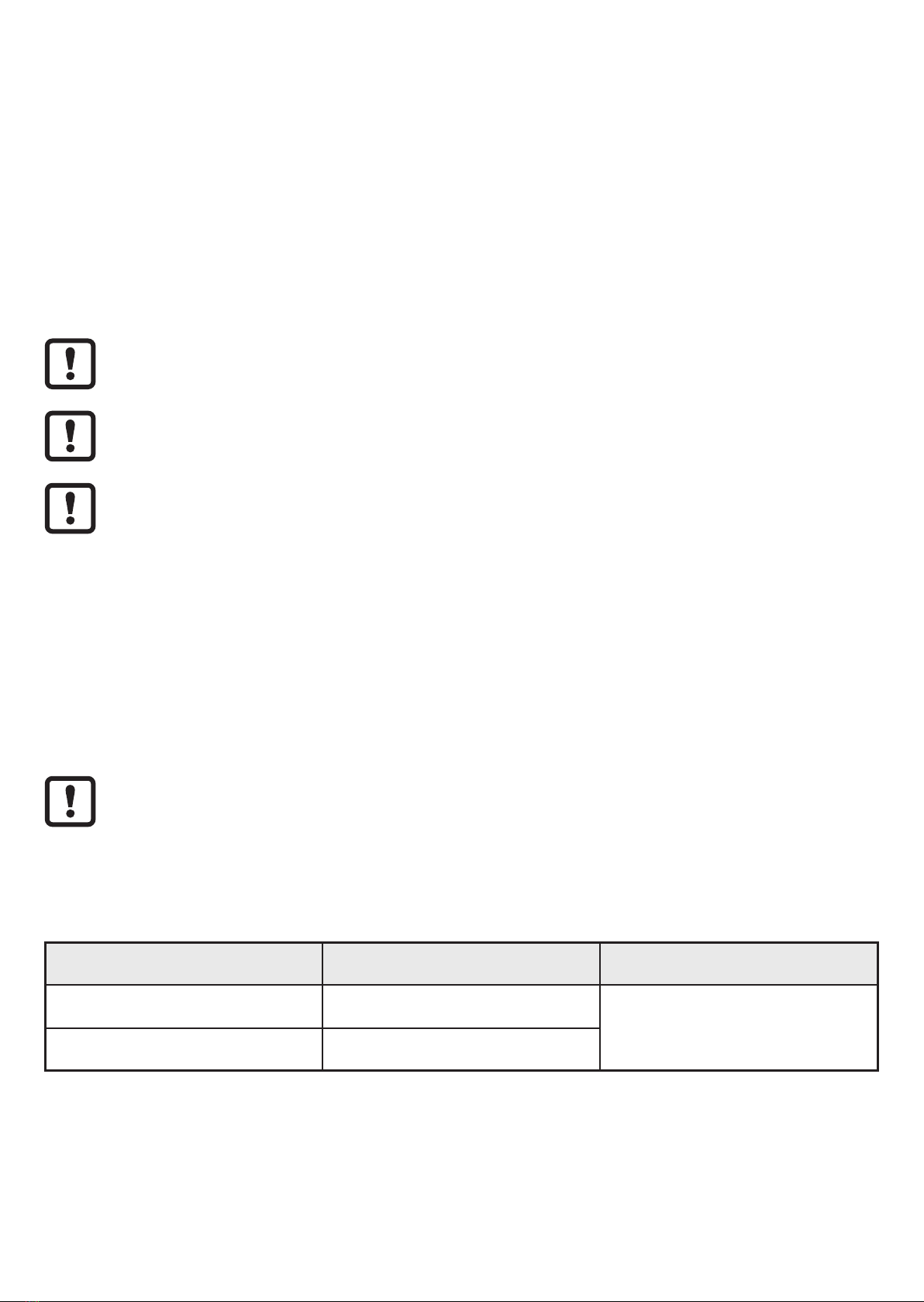
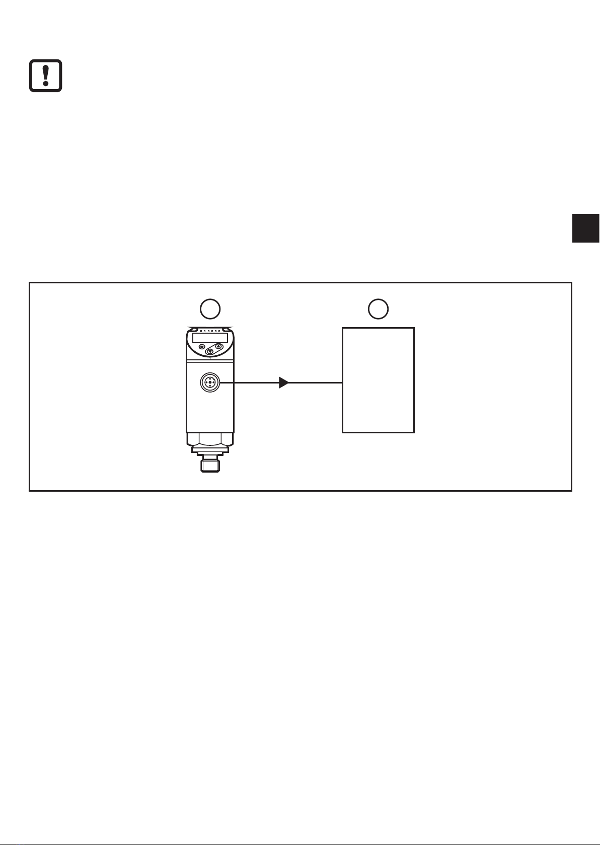
4�1 System integration�����������������������������������������������������������������������������������������5
4�2 Write protection against unauthorised access�����������������������������������������������7
4�3 IO-Link �����������������������������������������������������������������������������������������������������������7
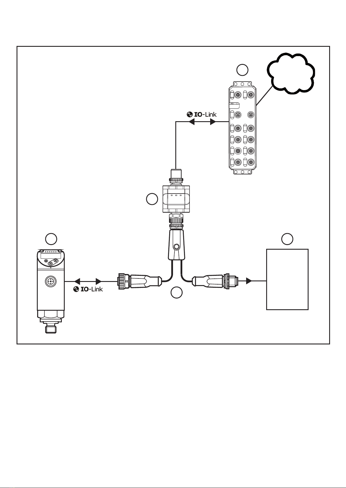
5 Installation������������������������������������������������������������������������������������������������������������7
5�1 Installation location / installation environment �����������������������������������������������7
5�2 Installation procedure ������������������������������������������������������������������������������������8
6 Electrical connection��������������������������������������������������������������������������������������������9
6�1 Electrical design of the output stage������������������������������������������������������������ 11
7 Display��������������������������������������������������������������������������������������������������������������� 11
8 Parameter setting ����������������������������������������������������������������������������������������������12
8�1 Parameters ��������������������������������������������������������������������������������������������������13
9 Operation�����������������������������������������������������������������������������������������������������������14
9�1 Operation and diagnostics display ��������������������������������������������������������������14
9�2 Delay times��������������������������������������������������������������������������������������������������15
10 Technical data and scale drawing��������������������������������������������������������������������15
11 Maintenance, repair and disposal ��������������������������������������������������������������������15
1 Preliminary note
Technical data, approvals, accessories and further information at
www�ifm�com�

3
UK
1.1 Symbols used
►Instructions
> Reaction, result
→Cross-reference
Important note
Non-compliance may result in malfunction or interference�
Information
Supplementary note�
2 Safety instructions
• The device described is a subcomponent for integration into a system�
- The manufacturer is responsible for the safety of the system�
- The system manufacturer undertakes to perform a risk assessment and to
create a documentation in accordance with legal and normative requirements
to be provided to the operator and user of the system� This documentation
must contain all necessary information and safety instructions for the operator,
the user and, if applicable, for any service personnel authorised by the
manufacturer of the system�
• Read this document before setting up the product and keep it during the entire
service life�
• The product must be suitable for the corresponding applications and
environmental conditions without any restrictions�
• Only use the product for its intended purpose (→ Functions and features).
• If the operating instructions or the technical data are not adhered to, personal
injury and/or damage to property may occur�
• The manufacturer assumes no liability or warranty for any consequences
caused by tampering with the product or incorrect use by the operator�
• Installation, electrical connection, set-up, operation and maintenance of the
product must be carried out by qualified personnel authorised by the machine
operator�
• Protect units and cables against damage�

4
3 Functions and features
The IO-Link data splitter E434xx allows decoupling of sensor information via
an IO-Link master without having to change the existing plant configuration or
controller�
The decoupled sensor information (e�g� switching output signals or analogue
values) can, for example, be recorded and evaluated in a cloud application.
Connection to or disconnection from the IO-Link master is possible at any time
without influencing the active machine functionality�
On delivery the data splitter is immediately ready for operation
(plug & play) for many applications (→ 8)�
On delivery only read access is possible (→ 4.2)�
The device can be configured for write access (→ 8)�
Sensors with pulse or frequency output on OUT1 (pin 4) are not supported.
►Check if the signal generated by the sensor is also provided via IO-Link�
►Check if the IO-Link transmission speed is fast enough for the
application (for example in case of very rapid switching frequencies)
→ Technical data sheet.
3.1 Application area
The device is suitable for use in industrial applications�
The connected sensor / actuator (→ Fig. 4.1) must have IO-Link
functionality�
For system integration the Y cable EVC843 is required (→ Accessories).
3.1.1 Device types
Order no. Electrical design Output logic (figures)
E43406 PNP → 6.1
E43410 NPN

5
UK
3.1.2 Restriction of the application area
The device must not be integrated into an existing IO-Link connection�
• The device is intended for indoor use only�
• For the possible influence of the sensor signals → 9.2�
4 Function
4.1 System integration
The prerequisite is a conventional sensor / actuator system without IO-Link that
consists of a sensor / actuator and a respective counterpart:
SIO
1 2
Fig� 4�1: Example of a conventional sensor system before integrating the data splitter
SIO = standard input-output mode; conventional switching mode
1: Sensor / actuator
2: Counterpart

6
The data splitter is installed using a Y cable between the sensor / actuator and the
controller:
SIO
1
3
4
2
5
Fig� 4�2: Example of a system integration
1: Sensor / actuator (IO-Link device) 4: data splitter E434xx
2: Controller / installation 5: IO-Link master
3: Y cable (EVC843)
In the configuration of fig. 4.2 the data splitter (4) switches the IO-Link device
(1) initially operated in the SIO mode to the IO-Link mode, connecting the newly
established IO-Link communication to the IO-Link master (5).

7
UK
At the same time the data splitter (4) provides again all initial SIO signals of the
sensor (1) to the controller / installation (2) so that the actual control task remains
unchanged�
The SIO signals are generated even without connected IO-Link master (5) or
active communication with the master so that the initial control task is carried out
at any time�
It is now possible to read process and diagnostic data or to configure the sensor
via the IO-Link master irrespective of the control task�
4.2 Write protection against unauthorised access
When the device is delivered the IO-Link master ((5) in fig. 4.2) only allows read
access to the connected IO-Link device (1). Write access is not possible until the
write protection has been removed�
To remove write protection:
►Connect and configure the device according to fig� 8�1 (→ 8)�
4.3 IO-Link
This device has an IO-Link communication interface which requires an IO-Link
capable module (IO-Link master) for operation.
The IO-Link interface allows direct access to process and diagnostic data (→ 4.1)�
Furthermore, communication with a USB IO-Link master is possible via a
point-to-point connection (→ 8)�
The IODDs necessary for the configuration of the data splitter and the connected
IO-Link device, detailed information about process data structure, diagnostic
information, parameter addresses and the necessary information about the
required hardware and software can be found at www�ifm�com�
5 Installation
5.1 Installation location / installation environment
►Install the unit at a suitable location�
- Observe the protection rating�
- Avoid heat build-up or impermissible heating of the device�
- Observe the maximum ambient temperature (→ Technical data).

8
►Mount the device so that it is accessible� In case of concealed installation, mark
the installation location in an appropriate way to ensure it can be found�
The maximum distance between the individual IO-Link components is 20 m�
Maximum distance between (3) and (2), fig. 4.2: → Technical data of the
connection cables used and of the other connected components� Maximum 30 m�
5.2 Installation procedure
If required, the device can be fixed with a mounting clip�
Mounting clip
(fasten with M4 screw or cable ties)
Mounting clip with attached device
The mounting clip is not supplied with the device (→ Accessories).
►Connect the device with a suitable cable�
►Connect the device to the IO-Link device, installation and IO-Link master using
the Y-cable EVC843 according to fig� 4�2�

9
UK
6 Electrical connection
The unit must be connected by a qualified electrician�
The national and international regulations for the installation of electrical
equipment must be adhered to�
Voltage supply according to EN 50178, SELV, PELV�
►Disconnect power�
►Connect the unit as follows:
Core colours
1
1
1
3
4
2
5
1
E434xx
EVC843
3
4
2
5
5 2 4 3
BN
2
WH
4
BK
3
BU
1
3 4
A
2
BK black
BN brown
BU blue
WH white
GY grey
Connections
(1): to the master
(2): to the Y cable
(3): to the IO-Link
device
(4): to the
installation (A): electrical separation
Connection of the data splitter E434xx:
43
2 1
to the master (1)
1: L+ (from the master)
2: not connected
3: L- (from the master)
4: C: IO-Link
3
1 2
4
5
to the Y cable (2)
1: L+ (from the installation)
2: C/Q: IO-Link
3: L- (from the installation)
4: switching output OUT1 / IO-Link1)
PNP (E43406) or NPN (E43410)
5: not connected

10
Using the Y cable EVC843 (→ 4.1) automatically ensures correct wiring�
Connection of the Y cable EVC843:
4
2 1
3
5
to the data
splitter (2)
1: L+ (from the installation)
2: C/Q: IO-Link
3: L- (from the installation)
4: switching output OUT1 / IO-Link1)
5: not connected
3
1 2
4
5
to the IO-Link
device (3)
1: L+ (from the installation)
2: switching output / analogue output OUT2,
if available
3: L- (from the installation)
4: C/Q: IO-Link
5: not connected
4
2 1
3
5
to the
installation (4)
1: L+ (from the installation)
2: switching output / analogue output OUT2, if
available
3: L- (from the installation)
4: switching output OUT1 / IO-Link1)
PNP (E43406) or NPN (E43410)
5: not connected
1) During parameter setting (→ 8)

11
UK
6.1 Electrical design of the output stage
►Observe the electrical design of the type used:
Type Electrical design Output logic (general)
E43406 PNP
L+
L
E43410 NPN
L+
L
Pin 2 and pin 5 of the IO-Link device (connection (3) (→ 6)) are connected
through to the installation side (4) in the Y cable EVC843. So for IO-Link
devices with a signal on pin 2 (e�g� second switching output or analogue
output) this signal is passed on unchanged to the installation.
Connections (1) and (2) of the data splitter are electrically isolated (A).
7 Display
1 32
Fig� 7�1
1: LED 1 (yellow); indication of the switching status OUT1, if available
2: LED 2 (green); operation display / fault
3: LED 3 (yellow); indication of the IO-Link communication (→ 9.1)

12
8 Parameter setting
To set the device parameters an IODD (IO Device Description) is needed.
More information: (→ 4.3)
For many applications the data splitter is ready for operation on delivery
(plug & play).
For connected IO-Link devices that support the automatic output
configuration (e�g� devices to the IO-Link smart sensor profile, switching
type) the data splitter does not need to be configured.
For operation on an IO-Link device that does not support the automatic
output configuration (→ 9.1) or if for example write protection is to be
removed the device must first be configured� To do so, the device has to be
connected according to fig� 8�1�
3
4
1
2
Fig� 8�1: Connection for parameter setting
1: Y cable (EVC843) 3: IO-Link master (e.g. USB version, E30390)
2: data splitter E434xx 4: PC / notebook
During parameter setting no IO-Link device must be connected to the
Y cable (1).
► Connect the data splitter (2) to an IO-Link master (3) via the Y cable (1).
► Connect the IO-Link master (3) to a PC (4).
►For parameter setting use an IO-Link capable software (→ Accessories).
►If necessary, download the IODD of the data splitter and integrate it in the
parameter setting tool used�

13
UK
8.1 Parameters
Name Description (1)
OutputConfiguration Selection between the automatic output configuration
(default) and the manual output configuration.
auto
Restore factory
settings
Default command to restore factory settings� ---
WriteProtect Write protection for the connected IO-Link device� If write
protection is active (parameter to 'on') write access of the
master is rejected by the data splitter�
Due to the system no feedback is given about rejected
write access to DPP (Direct Parameter Page →
IO-Link specification) nor about compatibility and validity
requests of actuator data by the master�
On
Removing write protection may jeopardise
the integrity of the application� Remove write
protection only after a thorough check of the
possible risks and effects�
SwitchingBit Bit in the IO-Link process data flow representing the
switching output OUT1� The parameter is only available
if OutputConfiguration is set to 'manual'�
0
►For the position of the corresponding bit see
the IODD description (PDF) of the connected
IO-Link device�
FOU1 Response of OUT1 in case of a fault� The parameter is
only available if OutputConfiguration is set to 'manual'�
Off
(1) Factory settings / on delivery
►After parameter setting connect the device again according to fig� 4�2 (→ 4.1)�
After removal of the write protection and correct integration of the IODD
(of the IO-Link device) the connected IO-Link device can be read and
configured by the IO-Link master�

14
9 Operation
►Check whether the unit operates correctly�
9.1 Operation and diagnostics display
Description LED 1 LED 2 LED 3
Supply voltage too low OFF OFF OFF
Device fault OFF flashes at 1 Hz OFF
Normal operation X ON X
IO-Link master connected X ON ON
No IO-Link master connected or
IO-Link master not detected
X ON flashes at 1 Hz
No IO-Link device connected or
IO-Link device not detected
IO-Link device provides no
switching output on pin 4
flashes at 1 Hz ON X
Short circuit on OUT1 flashes at 4 Hz ON X
Error with automatic output
configuration (→ 8.1)
flashes at 1 Hz ON X
Switching status OUT1 ON / OFF ON X
Parameter setting mode ON ON OFF
X: not defined

15
UK
9.2 Delay times
Because of the data splitter the response time for the switching output OUT1
slightly increases by the IO-Link process cycle time�
Example:
A sensor has a response time of e�g� approx� 100 ms� By switching to the IO-Link
mode this time is increased by the IO-Link process cycle time of e�g� 2�3 ms
(depends on the device, → Technical data of the connected IO-Link components).
So the total response time is approx� 102�3 ms�
10 Technical data and scale drawing
Technical data and scale drawing at www�ifm�com�
11 Maintenance, repair and disposal
►It is not possible to repair the unit�
►After use dispose of the unit in an environmentally friendly way in accordance
with the applicable national regulations�
►In case of returns ensure that the unit is free from dangerous and toxic
substances�
More information at www�ifm�com
This manual suits for next models
1
Table of contents
Other IFM Media Converter manuals

IFM
IFM RN6065 User manual

IFM
IFM DP1223 User manual

IFM
IFM TP323 Series User manual

IFM
IFM Efector 400 RU User manual

IFM
IFM RM8004 Application guide

IFM
IFM E70354 User manual

IFM
IFM AS-i CompactLineM12 AC2413 User manual

IFM
IFM RM8 Series Application guide

IFM
IFM RM8 Series User manual

IFM
IFM Efector 400 RM7 Series Application guide