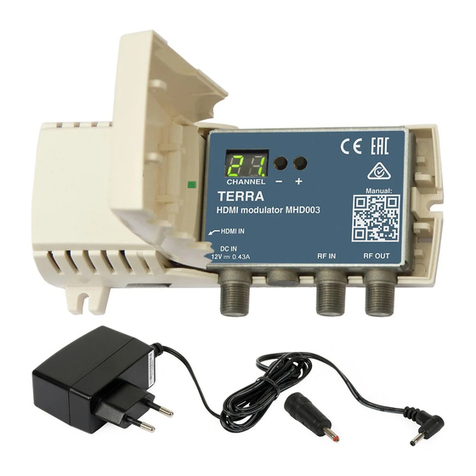
Terra MHD001P User manual

1
5
6
34
2
1
7
mounting hole mounting hole
8 9
2. 1.
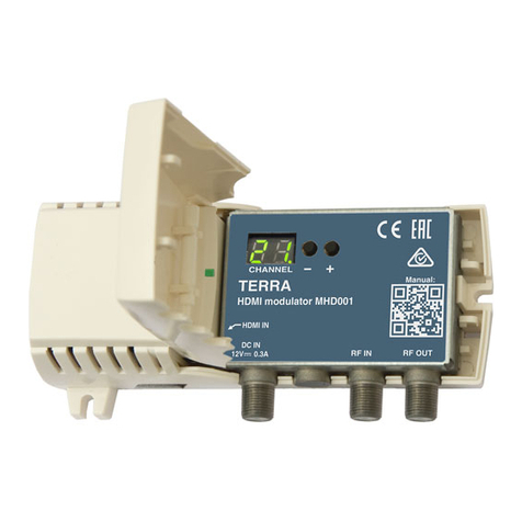
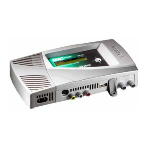
HDMI MODULATORS MHD001, MHD001P
1 -HDMI input connector
2 -DC IN - DC entry 3.5/1.3 mm (DC jack)
3 -RF IN - RF signal input connector (F type)
4 -RF OUT - RF signal output connector (F type)
5 -two-digit LED display
6 -DC voltage indicator
7 -exterior lid (open by hand)
8 -setting mode indicator
9- HDMI signal presence indicator Figure 1.
Vers. 1.02
PRODUCT DESСRIPTION
HDMI modulators MHD001, MHD001P are intended to encode HDMI video and audio signal to DVB-T signal and modulate
it in VHF and UHF ranges. MHD001P is packed with external mains power supply.
The modulators are intended for indoor use only. Suitable for moderate and tropical climates.
SAFETY INSTRUCTIONS
Installation of the modulator must be done according IEC60728-11 and national safety standards.
The modulator is powered from external power supply +12 V. This voltage is not dangerous to life.
Any repairs must be done by a qualied personnel.
To avoid the electric shock follow these instructions:
Do not plug mains power supply of the modulator into the mains until all cables have been connected correctly;
To disconnect the modulator from mains completely, disconnect plug of modulator power supply from mains socket;
Modulator shall not be exposed to dripping or splashing water and no objects lled with liquids, such as vases, shall be
placed on it;
Avoid placing modulator next to central heating components, near highly compustible materials and in areas of high humidity;
Before connecting the modulator to multimedia system, be sure that system is installed in accordance to national safety standards;
Devices of multimedia system should have easy access to disconnect them from the mains supply;
No naked ame sources, such as lighted candles, should be placed on modulator;
If the modulator has been kept in cold conditions for a long time, keep it in a warm room no less than 2 hours before
plugging into the mains;
Do not insert any objects into ventilation openings;
The ventilation should not be impeded by covering the ventilation openings with items, such as newspapers, table-cloths, curtains;
Mount the modulator on not ammable wall or in not ammable installation box in vertical position with power supply
located on the left. The modulator must be xed with steel screws Ø 3.5-4 mm. The screws are not included in a package;
From top, front and bottom of installed modulator must be at least 10 cm free space.
EXTERNAL VIEW
Manual:

2
INSTALLATION INSTRUCTIONS
Read the safety instruction rst.
Installation of system according standard IEC60728-11 ensures safety of personnel and prevents apparatus against
damaging due to lightning or other sources of overvoltage surges.
To change the modulator settings, open the plastic cover.
If RF IN connector on the modulator is not used, connect the 75 Ω load supplied.
To wall mount the modulator - screw the modulator to the wall (see Figure 1).
Do not connect TV antennas to modulator RF IN connector directly. If you intend to combine TV signals of antennas
and the modulator, plug in booster with output-to-input isolation ≥20 dB between antenna output and RF IN connector.
DEFAULT SETTINGS
1. Output channel 21;
2. Protection from unauthorized access OFF (Preset oF);
3. Service name MHD001 CH_21 (Preset 00);
4. Output signal attenuator 15 dB (Preset I5);
5. Output signal ON (Preset on);
6. Region Europe (Preset EU).
OPERATING
CHANGING OF SETTINGS
The modulator has two modes of operating:
1. normal: sets after plug in;
Output channel can be selected in normal mode by pressing buttons “-“ or “+” (see tables 2-6).
2. setting: to enter the setting mode press “-“ and “+” buttons simultaneously, to exit setting mode press “-“ and “+” buttons
simultaneously for 1 second. The setting mode is indicated by point after rst digit.
Select of necessary to change parameter by pressing button “-“ and set necessary parameter value by pressing “+” button.
1. Protection from unauthorized access setting (displayed L.C):
a) after switching settings mode, indicator displays protection from unauthorized access parameter name L.C;
b) select protection from unauthorized access parameter value by pressing “-“ button (displayed o.nor o.F) ;
c) change protection from unauthorized access parameter value by pressing “+“ button.
In the normal operation mode the symbol "LO" appears, if you try to change output channel in locked mode and output
channel remains unchanged.
2. service number:
a) press “-“ button (displayed n.O);
b) press “-“ button again (displayed number from 00 to 99);
c) change service name by pressing “+“ button.
When the service number is set to number greater that 00, the logical channel number will be added and service name is
set to MHD001 CH_service number. For New Zeland region service name is set according Table 7. When the service number
is set to 00, the logical channel numbering is o and service name is set to MHD001 CH_channel number.
Note: set dierent service numbers for cascaded modulators.
3. output attenuator:
a) press “-“ button (displayed A.t);
b) press “-“ button again (displayed number from 00 to 30);
c) change attenuator value by pressing “+“ button.
4. output signal switching:
a) press “-“ button (displayed r.F);
b) press “-“ button again (displayed o.nor o.F);
c) switching between RF ON and RF OFF by pressing button “+”, “on”- RF ON, “oF”- RF OFF.
5. region switching:
a) press “-“ button (displayed r.9);
b) press “-“ button again (displayed region name (see Table 1);
b) switching between regions by pressing button “+”.
REGION SETTING
Table 1.
Region Displayed Channel tables
Europe EU Table 2, Table 4
New Zealand n2 Table 2, Table 4
Australia AU Table 3, Table 5
United Kingdom Table 2, Table 4
Russia rU Table 2, Table 6
UK

3
REQUIREMENTS FOR EXTERNAL POWER SUPPLY UNIT (PSU) FOR MHD001
• Output voltage +12 V ± 1 V
• Output current > 0.3 A
• Ripple at single and/or double mains frequency < 10 mV p-p
• Ripple & noise < 180 mV p-p
• Output connector type 3.5/1.3 (+) plug or 5.5/2.1 mm (+) plug
• Short circuit protection
• Double insulated (marked )
• Meet EN 55022 class B conducted emisions requirements, measuring with grounded load
Caution (mark on rear side).
Risk of electric shock (mark on rear side).
This product complies with the relevant clauses of the European Directive 2002/96/EC. The unit must be recycled
or discarded according to applicable local and national regulations (mark on rear side) .
Equipment intended for indoor usage only (mark on rear side).
This product is in accordance to following norms of EU: EMC norm EN50083-2, safety norm EN60065 and RoHS norm EN50581.
This product is in accordance with Custom Union Technical Regulations: “Electromagnetic compatibility of technical
equipment“ CU TR 020/2011, “On safety of low-voltage equipment“ CU TR 004/2011.
This product is in accordance with safety standard AS/NZS 60065 and EMC standards of Australia.
PACKAGE CONTENTS
1. Encoder-modulator................................................................................. 1 pcs.
2. DC power supply adapter from 5.5/2.1 mm to 3.5/1.3 mm..................... 1 pcs.
3. Load 75 Ω, type F.................................................................................. 1 pcs.
4. External mains power supply +12 V 1 A max. (only for MHD001P) ....... 1 pcs.
5. User manual .......................................................................................... 1 pcs.
TECHNICAL CHARACTERISTICS
Type MHD001 MHD001P
Video input input signal type HDMI
video coding MPEG-4 AVC/H.264, Baseline prole 4.0
Audio input input signal type HDMI
audio coding MPEG-1 Layer II, AAC
H.264 encoder standard MPEG-4 AVC/H.264
Output resolution up to 1920x1080x30p
Transport stream automatic generation PAT, SDT, PMTs tables
processing
RF output DVB standard DVB-T
frequency range 174 - 230 MHz, 470-862 MHz
MER, typical 32 dB
modulation QAM64
channel bandwidth 7 MHz/ 8 MHz
shoulder attenuation > 36 dB
level/impedance 90 dBμV/75 Ω
output level adjustment 0÷-30 dB by 1 dB step
loop through frequency range/loss 45-862 MHz / ≤ 2.5 dB
Current consumption 12 ± 1 V 300 mA -
Power consumption - 100-240 V~ 50/60 Hz 4 W
Operating temperature 00 C ÷ +400 C
Dimensions/Weight (packed) 133x63x39 mm/0.18 kg 133x63x39 mm/0.34 kg
pr.
pr.
pr.
software control
pr.

4
Draugystes str. 22, LT-51256 Kaunas, Lithuania, tel.: +370 37
-
31 34 44, fax: +370 37
-
31 35 55
UHF BAND CHANNELS
(REGIONS: EUROPE, NEW ZEALAND,
UNITED KINGDOM, RUSSIA)
UHF BAND CHANNELS
(REGION: AUSTRALIA)
Bandwidth Channel Displayed Center freq.
5 05 177.5 MHz
6 06 184.5 MHz
7 07 191.5 MHz
7 MHz 8 08 198.5 MHz
9 09 205.5 MHz
10 10 212.5 MHz
11 11 219.5 MHz
12 12 226.5 MHz
Bandwidth Channel Displayed Center freq.
6 06 177.5 MHz
7 07 184.5 MHz
8 08 191.5 MHz
7 MHz 9 09 198.5 MHz
9A 10 205.5 MHz
10 11 212.5 MHz
11 12 219.5 MHz
12 13 226.5 MHz
Bandwidth Channel Displayed Center freq.
6 06 178 MHz
7 07 186 MHz
8 08 194 MHz
8 MHz 9 09 202 MHz
10 10 210 MHz
11 11 218 MHz
12 12 226 MHz
VHF BAND CHANNELS
(REGIONS: EUROPE, NEW ZEALAND,
UNITED KINGDOM)
Table 4
Table 5
Table 6
Table 7
Bandwidth Channel Center freq.
21 474 MHz
22 482 MHz
23 490 MHz
24 498 MHz
25 506 MHz
26 514 MHz
27 522 MHz
28 530 MHz
29 538 MHz
30 546 MHz
31 554 MHz
32 562 MHz
33 570 MHz
34 578 MHz
35 586 MHz
36 594 MHz
37 602 MHz
38 610 MHz
39 618 MHz
40 626 MHz
41 634 MHz
42 642 MHz
43 650 MHz
8 MHz 44 658 MHz
45 666 MHz
46 674 MHz
47 682 MHz
48 690 MHz
49 698 MHz
50 706 MHz
51 714 MHz
52 722 MHz
53 730 MHz
54 738 MHz
55 746 MHz
56 754 MHz
57 762 MHz
58 770 MHz
59 778 MHz
60 786 MHz
61 794 MHz
62 802 MHz
63 810 MHz
64 818 MHz
65 826 MHz
66 834 MHz
67 842 MHz
68 850 MHz
69 858 MHz
Bandwidth Channel Center freq.
20 473.5 MHz
21 480.5 MHz
22 487.5 MHz
23 494.5 MHz
24 501.5 MHz
25 508.5 MHz
26 515.5 MHz
27 522.5 MHz
28 529.5 MHz
29 536.5 MHz
30 543.5 MHz
31 550.5 MHz
32 557.5 MHz
7 MHz 33 564.5 MHz
34 571.5 MHz
35 578.5 MHz
36 585.5 MHz
37 592.5 MHz
38 599.5 MHz
39 606.5 MHz
40 613.5 MHz
41 620.5 MHz
42 627.5 MHz
43 634.5 MHz
44 641.5 MHz
45 648.5 MHz
46 655.5 MHz
47 662.5 MHz
48 669.5 MHz
49 676.5 MHz
50 683.5 MHz
51 690.5 MHz
52 697.5 MHz
53 704.5 MHz
54 711.5 MHz
55 718.5 MHz
56 725.5 MHz
57 732.5 MHz
58 739.5 MHz
59 746.5 MHz
60 753.5 MHz
61 760.5 MHz
62 767.5 MHz
63 774.5 MHz
64 781.5 MHz
65 788.5 MHz
66 795.5 MHz
67 802.5 MHz
68 809.5 MHz
69 816.5 MHz
70 823.5 MHz
71 830.5 MHz
72 837.5 MHz
73 844.5 MHz
74 851.5 MHz
75 858.5 MHz
Table 2 Table 3
VHF BAND CHANNELS
(REGION: AUSTRALIA)
VHF BAND CHANNELS
(REGION: RUSSIA)
SERVICE NAMES FOR NEW ZEALAND
Displayed service
number Service name
01 SKY1
02 SKY2
03 SKY3
04 SKY4
05 SKY5
06 APPLE TV 1
07 APPLE TV 2
08 APPLE TV 3
09 APPLE TV 4
10 APPLE TV 5
11 BLU-RAY 1
12 BLU-RAY 2
13 BLU-RAY 3
14 BLU-RAY 4
15 BLU-RAY 5
This manual suits for next models
1
Other Terra Modulator manuals
