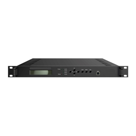
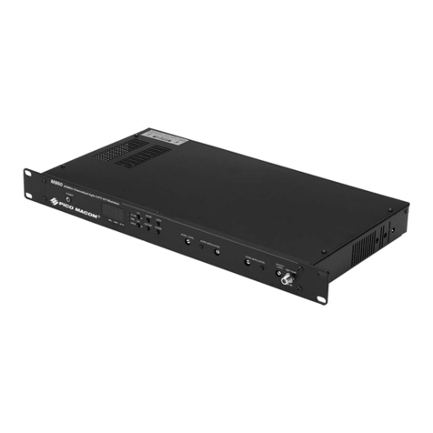
Terra S2C16 User manual

2
Vers. 1.09
16 channels DVB-S/S2 to DVB-C
transmodulators
S2C16, S2C16P
User's manual
●English
●Russian

3
Stand-alone headend S2Cbox
1. Product description
Device is a 16 channels transmodulator with DVB-S/S2 input and DVB-C output. It has 4 main and 2 auxiliary
SAT ports for connecting SAT signal. Integrated RF multiswitch allows connection 16 demodulators to SAT
ports. Demodulated transport stream reaches processor, which lters services, modies SI (Service
Information), generates NIT (Network Information table), LCN (Local Channel Number), restamps PCR
(Program Clock Reference). Then transport stream is forwarded to 16 QAM modulators, which produces 16
independent DVB-C RF signals.
All of the congurations can be changed by using the Web Interface.
S2C16P version of transmodulator with redundant power supply (PS) has two PS to increase reliability of
supply voltages.
Transmodulator can be used as a stand alone device.
The product is intended for indoor usage only.
2. Safety instructions
Installation of the transmodulator must be done according IEC60728-11 and national safety standards.
Transmodulator is powered from mains 230 V~. This voltage is dangerous to life.
Any repairs must be done by a qualied personnel only.
To avoid the electric shock follow these instructions:
● Do not plug transmodulator into the mains supply if the power cord or plug is damaged.
● To disconnect the transmodulator from the mains completely, disconnect plug from mains socket.
● The mains socket must be easily accessible.
● The transmodulator shall not be exposed to dripping or splashing water and no objects lled with
liquids, such as vases, shall be placed on it.
● Avoid placing device next to the central heating components and in areas of high humidity.
● No naked ame sources, such as lighted candles, should be placed on transmodulator.
● If the device has been kept in cold conditions for a long time, keep it in a warm room no less than 2
hours before plugging into the mains.
● Do not insert any objects into ventilation openings.
● The ventilation should not be impeded by covering the transmodulator with items, such as
newspapers, table-cloths, curtains.
● Mount the transmodulator on not ammable wall or in not ammable installation box in vertical
position with power supply located on the right.

4
3. Specications
software control
* recommended level imbalance between inputs < 10 dB
** without external DC load; with maximal external DC load up to 44 W
pr.
Number of transponders 16
SAT frequency range (950 - 2150 MHz)
ports input level/impedance 45-85 dBµV/75 Ω*
LNB powering and control V, Lo 0 V / 13 V
H, Lo 0 V / 18 V 500 mA max. total
V, Hi 0 V / 13 V 22 kHz or DiSEqC
H, Hi 0 V / 18 V 22 kHz or DiSEqC
Aux 1 0 V / 13 V 250 mA max. total
Aux 2 0 V / 18 V
return loss ≥14 dB
modulation DVB-S demodulator (QPSK) DVB-S2 demodulator (QPSK, 8PSK)
symbol rate 2 ÷ 45 MS/s 2 ÷45 MS/s (QPSK), 2 ÷31.5 MS/s (8PSK)
code rate 1/2, 2/3, 3/4, 5/6, 7/8 QPSK 1/2, 3/5, 2/3, 3/4, 4/5, 5/6, 8/9, 9/10
8PSK 3/5, 2/3, 3/4, 5/6, 8/9, 9/10
roll off 35 % 20 %, 25 %, 35 %
signal processing ETSI 300 421 ETSI 302 307
RF output frequency range 48 - 858 MHz, by step 100 kHz
RF channel allocation independent from other channels
output level per carrier/impedance 90 dBµV/75 Ω
total output level adjustment 15 dB by 0.5 dB step
carrier output level adjustment +3 dB...-3 dB by 0.5 dB step
MER ≥43 dB
modulation DVB-C QAM16, QAM32, QAM64, QAM128, QAM256
channel bandwidth / symbol rate 4...8.3 MHz / 3.5 ÷ 7.2 MS/s
return loss ≥14 dB
roll off 15 %
signal processing EN 300 429, ITU-T J.83 A (Annex A)
loop through (RF IN) frequency range 45-862 MHz
loop through (RF IN) loss 3 dB
test point (directional) -20 dB
Input data rate max. 90 Mbps per transponder
Supply voltage limit values 190-250 V~ 50/60 Hz
Power consumption** up to 29 W
Operating temperature range -10o ÷ +55o C
Dimensions/Weight (packed) 373x135x69 mm / 3.1 kg (S2C16) 500x135x69 mm / 3.54 kg (S2C16P)
Management port 10/100 Base-T Ethernet
Default IP address 192.168.1.10
Default login information Username: admin
Password: admin
pr.
pr.
pr.
pr.
pr.
pr.
pr.
pr.

5
4. External view
Picture 1. External view of the S2C16
Picture 2. External view of the S2C16P
19
21
22
20
1
2
3
4
613 7 8
14
15
9
16
10
17
11 12
5
18

6
1. V, Lo - vertical Lo band SAT input. +13 V output to LNB can be supplied from this connector.
2. H, Lo - horizontal Lo band SAT input. +18 V output to LNB can be supplied from this connector.
3. V, Hi - vertical Hi band / DiSEqC SAT input. +13 V/22 kHz output to LNB can be supplied
from this connector.
4. H, Hi - horizontal Hi band / DiSEqC SAT input. +18 V/22 kHz output to LNB can be supplied from
this connector.
5. AUX INPUT1 - auxiliary 1 SAT input. +13 V output to LNB can be supplied from this connector.
This port can be accessible from 9th -16th demodulators only.
6. AUX INPUT2 - auxiliary 2 SAT input. +18 V output to LNB can be supplied from this connector.
This port can be accessible from 9th -16th demodulators only.
7. TEST OUT - -20 dB RF output signal test point for testing and trouble shooting (without loop
through RF input).
8. RF OUT - RF output.
9. RF IN - RF loop through input. An output of another transmodulator can be connected here.
10. 10/100 Mb ETH - Ethernet control port.
11. Ethernet link indicator. Green LED indicates valid Ethernet link.
12. Ethernet activity indicator, yellow LED.
13. Startup progress and channel status indicators:
1. Indicate the progress of startup when the device is powered on or rmware upgrade is going on.
2. Each indicator indicate channel status when the device is up and running:
Does not glow when the channel is completely inactive.
Glows yellow if either demodulator or modulator is active, but not both.
Glows green if demodulator and modulator are active and there are no any errors related to channel
processing.
Glows red if demodulator and modulator are active and any error appeares in channel processing.
14. ADDRESSED - addressing indicator. It blinks on when the device is being accesed via control panel.
15. STATUS - error indicator. Red light indicates, that at least one error exists at the moment.
16. Reset button. Intended for two functions:
1. Press this button at operating time to restart the device.
2. Restore default IP address and admin’s password. Press the button when the device is turned off.
Keep it pressed and plug the powering on. Release the button not earlier than yellow LEDs (13)
will start light on. After that default IP address and default admin’s pasword will be restored. All the
rest parameters will be unchanged and device will keep operating as previously was set up.
17. Functional grounding clamp.
18. Power cord.
19. Power cord of the left power supply.
20. Power cord of the right power supply.
21. Power Left. Indicates correct DC voltages from left power supply.
22. Power Right. Indicates correct DC voltages from right power supply.

7
5. Installation instructions
Read the safety instruction rst.
Installation of system according standard IEC60728-11 ensures safety of personnel and prevents apparatus
against damaging due to lightning or other sources of overvoltage surges.
Mount the transmodulator on not ammable wall or in not ammable installation box in vertical position with
power supply located on the right.
Transmodulator must be xed with steel screws Ø 4-5 mm. The screws are not included in a package.
If any RF connector on the transmodulator is not used, connect the 75 Ω load supplied.
Connect power plug of transmodulator to the mains when functional grounding and RF cables are connected
correctly.
Shielded cable is recommended for Ethernet connection.
It is recommended to connect power plugs of S2C16P to different lines of the mains or one to the line
directly, another through uninterruptible power source (UPS).
System indicates error when one of PS is disconnected. Disconnected PS does not disturb working
of other PS.
6. Operation
Power on the device. Yellow LEDs (13) will light on from the left to the right one by one. It indicates powering
on progress. When powering on is nished, device will run according to the latest used conguration. LEDs
will indicate the status of each channel. The led is turned off when particular demodulator and RF output is
disabled. Green LEDs (13) indicates, that whole channel path is active, no errors detected. Red LEDs (13)
indicates an error in the channel. Yellow LEDs indicates, that either demodulator or modulator is activated
and the full path is congured not properly.
Device monitores PMT (Program Map Table) and CAT (Conditional Access Tables) of every active service
constantly and updates transport stream parameters to the output if any changes detected, for ex: new PIDs
(Packet Identier) detected or removed. So the end-equipment should detect any changes of transport
stream automatically as well. The exception is very rare situation, when the same PMT PID is shared
between several services. In this case, PMT monitoring is disabled for these services.
7. Initial conguration
All modules leave the factory with this control over Ethernet interface IP address: 192.168.1.10. In order to
avoid conicts with other IP addresses, it is necessary to perform an initial conguration in the local mode.
Subsequently, it will be possible to access the module via local area network (LAN), either to change the
conguration or to check the operating status.
The modules leave the factory with the following control over Ethernet interface TCP/IP conguration:
IP address of the module: 192.168.1.10
Subnet mask: 255.255.255.0
Default Gateway: 192.168.1.1
Figure 3. Login window

8
To access each module, use a personal computer (PC) equipped with an Ethernet card and RJ-45 cable
(CAT-5E or CAT-6). The IP address of the PC/MAC must be congured within the following range: 192.168.1.2
- 192.168.1.254 (do not use 192.168.1.10, since this is the IP address of the module to be congured). To start
the conguration of the module, open your web browser and type in the following direction: http://192.168.1.10.
The login prompt will appear on the screen (see Figure 3).
Access to the module is protected by user name and password. The default user name and password is
admin. Enter the user name and password and click on “Login” button.
NOTE*: the default password - admin - can (and must) be changed as explained in the section 8.8.5
“User management”. During initial conguration you need to change the default control interface TCP/IP
conguration as explained in the section 8.6 “IP parameters”.
NOTE**: If you are using Internet Explorer Web browser, supported versions are version 10 or higher.
Control interface IP address reset to default procedure: press the “RESET” [16] button for more than
3 seconds and release it. After this operation the control interface IP address will be set to 192.168.1.10, user
name and password set to admin.
8. Control panel
8.1. Main window
„Device information“ table shows main device information – serial number, device model, software
version, etc.
Parameter „Title“ can be changed by pressing „Change“ button. This title will be displayed as a browser title
and will be seen on the right top side of the browser.
„Output bitrates“ table shows the output bitrate status of each channel in real time (Picture 4.). Horizontal bar
shows percentage of used available bandwidth of the channel. The 1st number right to the bar shows actual
bitrate in Mbps. Next number shows maximum allowed bitrate in the channel and it depends on modulation
parameters. Ensure, that maximum actual bitrate would not reach more than 95% of available bandwidth.
Otherwise bitrate overow may occur.
„Diagnostic information“ table shows actual errors.
„Temperature measurement“ table shows temperature of several points of the device - demodulator,
modulator and internal temperature. Ensure, that none of these temperatures would reach 90°C degree.
Otherwise output quality parameters may get worse. Reaching 110°C may damage the device.

9
"Supply voltage" shows main and LNB voltages.
S2C16P: “Power supplies” table shows status of each PS. Green ON indicates that both voltages from PS
are correct. Red OFF indicates disconnected PS or it’s voltages are out of range.
Picture 4. Output bitrates
8.2. LNB settings
Picture 5. Structure of SAT inputs

10
Picture 5 shows internal structure of satellite inputs. Each SAT port has individual settings, where a power
supply can be switched on/off, LNB Lo/Hi frequency or DiSEqC parameters set up:
V, Lo: 0 V or +13 V;
H, Lo: 0 V or +18 V, see picture 6.
V, Hi: 0 V or +13 V 22 kHz. This port supports DiSEqC as well, see picture 7.
H, Hi: 0 V or +18 V 22 kHz. This port supports DiSEqC as well;
Aux In1: 0 V or +13 V. When Aux In1 LNB power is set to „RF V,Hi“, this port is disabled, see pictures 5, 8.
Aux In2: 0 V or +18 V. When Aux In2 LNB power is set to „RF H,Hi“, this port is disabled.
Picture 6: LNB power setup window
Picture 7: LNB DiSEqC parameters
setup window
Picture 8: LNB power setup of AUX inputs
RF signal from Aux In1 and Aux In2 ports can be connected to 9-16th demodulators only or be disabled.
When Aux In1 LNB power is set to 0V or +13V, switch S1 connects Aux In1 port to 9-16th demodulators and
connects DC 0V or +13V for LNB. When Aux In1 LNB power is set to „RF V,Hi“, switch S1 connects 9-16th
demodulators from port Aux In1 to port V,Hi, disconnecting DC from this port, see picture 5.
Summary output current for LNB from ports V,Lo, V,Hi, H,Lo, H,Hi is shown in Specications independing
from Aux In1, Aux In2 settings.
Summary output current for LNB from ports Aux In1, Aux In2 is shown in Specications independing from
another ports settings.
8.3 RF inputs
16 demodulators can be set up in this section. See picture 9. „SAT input“ parameter can switch demodulator off
or connect to any available RF input. Demodulators 1-8th can connect only to V,Lo/H,Lo/V,Hi/H,Hi inputs.
Depending on „Aux In/LNB Power“ parameter of „LNB Settings“ section, in case of „SAT input“ 3rd and 4th
selection, demodulators 9-16th will be connected either to V,Hi/ H,Hi or to Aux In1/2 ports.
„Input frequency“ parameter is a frequency of transponder in MHz. Ensure, that SAT IF frequency
(FRtransponder - LNB Lo/Hi) ts into demodulator’s input frequency range.
In case of DiSEqC, device will try (if possible) to automatically select Lo or Hi frequency to t into the IF
frequency range.
„Symbol rate“ parameter is a symbol rate of transponder in kSym/s.
„Modulation standard“ allows to select modulation type of DVB-S or DVB-S2.
Press „Update“ button to set new parameters.
There are various status parameters of input signal right to the „Update“ button. „Lock status“ can have
following values:

11
- „Inactive“, when the input channel (demodulator) is turned off;
- „Locked“, when demodulator is locked to the transponder;
- „Unlocked“, when demodulator is unlocked. This state generates error in diagnostic window as well. If the
channel is not used, it’s recommended to turn it off instead of leaving unlocked. It will save power consumption.
„RF level“ and „SNR“ (Signal Noise Ratio) are measured parameters of input signal. „Bitrate“ is the transport
stream’s bitrate of the transponder. PER (Packet Error Ratio) shows the ratio of invalid received packets and
total received packet. A sign „<“ before the value means, that there was no any errors within that number of
packets. To reset PER counters, simply click onto the PER value.
Picture 9: RF inputs
RF level and SNR parameters can be monitored for error generation, if values drops down under specied
thresholds. Select "RF level" or/and "SNR" checkbox in the "Error thresholds" table (see Picture 10) to enable this
feature.
For example: if RF level threshold is 50 dBμV and RF level will drop less than 50 dBμV - diagnostic error will
be generated.
Picture 10: Error thresholds

12
8.4 RF outputs
Picture 11: RF outputs
16 independent QAM modulators can be setup in this section. There is no requirement for channels to be
adjacent or sorted by frequency, see picture 11. Each channel can have own constallation
QAM-16/32/64/128/256, symbol rate 3500..7200 Mbps. Note, that symbol rates higher than 6956 kSym/s
will exceed 8 MHz bandwidth, so these symbol rates should be used carefully.
„Output frequency“ parameter can be entered manually or selected as a channel from combobox. Only
C21(474 MHz)...C69 (858 MHz) can be selected from the list. If you need any other frequency – just add it
manually. Frequency step is 0.1 MHz.
RF level for each channel can be adjusted in a range of -3...+3 dB. „Enable“ checkbox will enable channel
to the output. Global attenuator can be entered up to 15 dB.
Press „Update“ to change settings. In case, if any modulation parameter was changed, whole 16 modulators
will be restarted with new settings. Exceptions are „RF level“ and „Attenuator“. Changes in these parameters
will not restart the modulator.
8.5 TS outputs
Several tables related to NIT generation exist in this section. „Global TS parameters“ (picture 12) describes
following TS parameters:
Picture 12: Global TS parameters

13
- "Network ID" is unique within the geographical region dened by the “country_code”. For a cable network,
usually this is a single country code plus 0x2000 (8192). If there are more modulators in the network, they
must have the same Network ID.
Proper value depending on your country and operator can be found here:
http://www.dvbservices.com/identiers/network_id?page=1
- "Private data specier" (in hex format) can be inserted in the NIT table for proper LCN description. This
value is described in TS 101162 specication. NorDig standard requires 00 00 00 29 value, UK should use
00 00 23 3A value. Other options can be found here:
http://www.dvbservices.com/identiers/private_data_spec_id?page=1
The parameter will not be inserted into NIT if value is set to zero.
- „Network name“ is the name of the network.
- „Timezone“ parameter is used for proper time records in logs. It has no effect to broadcast.
- „Date and time source“ is a channel for a source of time. It is used for proper time records in logs and has
no effect to broadcast. All original TDT/TOT (Time Data Table/ Time Offset Table) PID 20 pass directly from
demodulators to each output without modication.
The 2nd table in the page describes "Transport stream ID" and "Original network ID" of each channel
(see picture 13). Each stream in a network must have unique ID, called „Transport stream ID“. An
"Original Network ID" is dened as the “unique identier of a network”. It can be linked to "Network ID" or
used value from this location:
http://www.dvbservices.com/identiers/original_network_id?page=1
Picture 13: Transport stream and original network IDs
In case of transparent mode, "Original network ID" and "Transport stream ID" elds will be disabled. These
values will be the same as in input transport stream, and will be updated automatically if any changes detected.
Very important part in this page is the 3rd table (picture 14), where other streams in the network can be
described.

14
Picture 14: Description of other streams in the network
Every channel in the network must be described in NIT. Otherwise TV automatic channel tuning function will
not nd all channels. So, if there are more modulators in the network, all channels must be included in this
table. If there are more devices, which are controlled via Ethernet, all broadcast information can be captured
automatically by adding it’s IP address and pressing „Load“ button. In case if the same frequency was added
already, that record will be updated. Otherwise, a new record will be inserted.
All listed frequencies will be monitored in the network via standard SSDP protocol. NIT tables will be
regenerated if any change in any listed frequencies detected. Be sure, Ethernet router is congured properly
to pass SSDP packets (239.255.255.250:1900 and 239.255.255.246:7900).
8.6 IP parameters
All device IP settings can be setup here – IP address, subnet mask, gateway, DNS (Domain Name System),
see picture 15. DNS server is used for e-mail sending only.
Device can take all IP settings from DHCP server as well, if the "Enable DHCP" checkbox is checked. Device
will be accessable at the new IP address, which provides DHCP server. Control panel will NOT redirect to
the new address automatically. This is user's responsibility to learn, which IP address the DHCP server has
assigned to the device.
This feature is for advanced users only.
IP parameters will be updated immediately after pressing „Update“ button and redirect to new location.
Picture 15: IP parameters
The device can send e-mail reports if errors
were detected (since 1.12 software version).
SMTP protocol is used for that. Picture 16 shows
parameters related to this feature. "Enable e-mail
error report" checkbox enables error monitoring.
All errors within "timeout" period will be gathered, and send to the e-mail address, provided in "Receiver
e-mail address" input box. Comma separated e-mail addresses can be used to send report to multiple
addresses. The timer will be started as soon, as the rst error is detected and stopped when e-mail is sent.
The timer will be restarted again if a new error will appear.
"Sender e-mail address" can be used as authentication in the SMTP server side.
Secured e-mail send protocol (TLS - Transport Layer Security) is available since 1.26 software release.
Port numbers used for e-mails sending usually are 25 for regular connection, 465 for secured TLS connection.
Internet service provider may use other ports.
SSL (SMTPS) protocol is not supported.
Picture 16: E-mail settings

15
Figure 17 "SNMP settings" is located in “IP parameters” tab.
The description of the SNMP conguration parameters:
"sysLocation", "sysContact", "sysName" acts as contact
information of device owner.
"Read Community" - community name acts as a password that
is shared by multiple SNMP agents and one or more SNMP
managers. "Read Community" password is used for read-only
access to the modules parameters.
"Write Community" - is the password used for read-write access
to the modules parameters.
"Enable TRAP" - SNMP traps are alerts generated by
agents on a managed device. Check this box to enable
TRAP
generation. The module generates traps when the diagnostic
message occurs.
"TRAP Community" - is the password used for accessing of
TRAPS.
"Trap IP #1","Trap IP #2", "Trap IP #3" - IP addresses of hosts
with SNMP managers, where TRAPS will be send.
Use downloaded MIB le with your SNMP manager for accessing
all device parameters.
Picture 17: SNMP settings
8.7 Services
One channel at a time can be setup in this page. Select proper channel from the list at „Choose input channel“
combobox (see picture 18).
Picture 18: Services
A list of scanned services of selected channel will appear. „Rescan“ button will load all service information of
that channel. „List of services“ table shows a list of available services. Icon before the service name indicates
service type. Bitrate of each service is measured in real time. „LCN“ eld is a Logical Channel Number. Every
service can have a „channel number“ and TV will sort channels according to it. Just ensure, that all services
in all channels have different numbers. Value 0 means, that LCN for that service is not used at all and TV will
sort these channels according to it’s own rules. If channel numbers are added, but TV does not recognize it,
check the following:
- If TV supports LCN?
- If Network ID and Original Network ID values are valid for the country, which is selected on TV?
„Enable“ checkbox enables the service to the output.
Press onto „+“ sign and service information will be extended (see picture 19).

16
Picture 19: Service details
Service title and provider can be edited (multilanguage character support). „Scrambled ag“ will be inserted
into SDT (Service Description Table). Unchecking this checkbox will not descramble the content. It only
carries information about the scrambling status of the service.
Individual streams can be disabled as well.
Note: transparent mode will ignore all these settings.
Press onto „Update“ button to save changes and execute.
In case of transparent mode, all services of transponder will be passed to the output, including original PAT,
SDT, PMT, EIT, CAT tables. Note, that "Original network ID" and "Transport stream ID" values will be used
original.
Use the following steps to turn on transparent mode: press "Rescan" button to scan services for the rst time;
mark "transparent mode" checkbox, like in picture 18; press "Update".
8.8 System menu
This menu tab contains following submenu items: “Event logs”, “Export parameters”, “Import parameters”,
“Firmware upgrade”, “User management”, “Restore defaults“, “Reset the device“, “Language”. Mouse over
to show the list of this submenu.
8.8.1 Event logs
Various important events, errors, warnings will be logged into the system (see picture 20).
Picture 20: Event logs
Each record has an event type, which can be used to lter particular messages. Just select checkboxes in
the „Logs ltering“ table and press „apply“. Other messages will be hidden.
„Erase logs“ button will erase all logs from the system.
Each record has a log time when the event appeared. Device has internal clock and it’s value is updated from
the transport stream. Timezone takes effect there, which can be setup at „TS output/Timezone“.
8.8.2 Export parameters
All settings of transmodulator can be exported for backup or copying to another device. Press “Export parameters”
and “parameters.xml” le will be downloaded to PC. This le can be imported only to the same type of device.

17
8.8.3 Import parameters
Exported parameters can be imported back to the device. Press onto “Click to select le” button
(see picture 21) to select exported le.
Picture 21: Import parameters
Press “Upload” button to send the le to the device. Several seconds will take to update all parameters after
le upload. After that, device will start to work with new conguration. No restart requires.
8.8.4 Firmware upgrade
Device rmware can be upgraded via web browser. Press onto “Click to select le” button and select rmware
binary le. If valid le was selected, a version number of new rmware will be displayed. Otherwise an error
message will appear. Press “Upload” button to upload new rmware to the device. Upload progress bar will
appear and may take about a minute or more, depending on the size of a le and a network connection
speed. A message will be displayed asking to restart the device when the le was sent to the device. New
rmware will be programmed into the device only after restart. Red indicators of the device will light on left
to right and then back right to left indicating the progress of programming. It may take additional minute or
more to nish the process. Device will startup with a new rmware and continue to operate with previous
parameters. Additional new rmware features (if any) may need to setup additionally to take affect.
Avoid power supply interruption when a programming process is going on.
Device has possibility to load software revision history and check availability for new software release. Click
onto “Check online” link. If computer (not device!) has internet access, it will show a list of all software
releases with links to binary les.
Picture 22: Firmware upgrade and software revision history
Binary le can be downloaded and saved to computer (see picture 23). After that, use the rmware upgrade
method as described above.

18
This product complies with the relevant clauses of the European Directive 2002/96/EC. The unit must be recycled
or discarded according to applicable local and national regulations.
Equipment intended for indoor usage only.
Equipment is double insulated from the mains, with functional earthing.
Functional earthing. Connect to the main potential equalization.
This product is in accordance to following norms of EU: EMC norm EN50083-2, safety norm EN60065, RoHS norm
EN50581, RED norm ETSI EN 303 372-2.
This product is in accordance with Custom Union Technical Regulations: “Electromagnetic compatibility of technical
equipment“ CU TR 020/2011, “On safety of low-voltage equipment“ CU TR 004/2011.
This product is in accordance with safety standard AS/NZS 60065 and EMC standards of Australia.
8.8.5 User management
User may change a password here. Length of password up to 16 symbols. Type current password and double
enter new password to change it.
If logged in user has admin role, new users can be added on another table (see picture 23).
Picture 23: User management
Enter it’s username, password, select a role and press „Add“ button.
Only administrator (user with a role „admin“) may manage other users.
8.8.6 Restore defaults
All parameters will be restored back to factory defaults after conrmation. The exception – IP address and
users – these parameters will be unchanged. To restore IP address and system password to system defaults,
see „reset“ button at section 4, pos.16.
Several seconds can take to restore all parameters, so be patient.
8.8.7 Reset the device
Device will be restarted after conrmation to do it. This is an alternative to pressing a „reset“ button when the
device is operating.
8.8.8 Language
Device control panel supports several preinstalled languages. A change of language requires system restart.
Note, that all previously logged records will remain in previous language.
Additional languages can be installed under request. Contact our distributors for such possibility.

19
16-и канальные SAT в QAM трансмодуляторы S2C16, S2C16P
1. Назначение изделия
Изделие является 16-и канальным трансмодулятором с входом DVB-S/S2 и выходом DVB-C. Для
подключения SAT сигналов предназначены 4 основных и 2 дополнительных SAT порта. Интегрированный
RF мультисвитч позволяет к SAT портам подключить 16 демодуляторов. Демодулированный
транспортный поток достигает процессор, который фильтрует сервисы, модифицирует SI (сервисную
информацию), генерирует NIT (таблицы сетевой информации), LCN (номер местного канала),
обновляет PCR (Program Clock Reference). Затем транспортный поток направляется к 16-и QAM
модуляторам, которые формируют 16 независимых DVB-C RF сигналов.
Все конфигурации могут быть изменены с помощью Web интерфейса.
Трансмодулятор S2C16P имеет два источника питания (PS) для повышения надежности напряжения
питания.
Трансмодулятор может быть использован в качестве самостоятельного блока.
Трансмодулятор предназначен работать в закрытом помещении.
2. Инструкция по электробезопасности
Инсталляция трансмодулятора должна быть проведена в соответствии с требованиями
IEC60728-11 и национальных стандартов безопасности.
Трансмодулятор работает от сети 230 V~. Напряжение опасно для жизни.
Ремонтировать трансмодулятор может только квалифицированный персонал.
Чтобы избежать поражения электрическим током:
● Не подключайте трансмодулятор в сеть, если шнур или вилка питания повреждены.
● Трансмодулятор от сети питания полностью отключается с помощью вилки питания.
● Розетка питания должна быть легко доступна.
● Не устанавливайте трансмодулятор в местах где есть возможность попадания брызг
или капель воды.
● Не ставьте сосудов (напр. ваз) с водой или другими жидкостями вблизи трансмодулятора,
чтобы избежать попадания жидкостей внутрь трансмодулятора.
● Не устанавливайте трансмодулятор вблизи приборов отопления и вблизи
легковоспламеняющихся материалов, а также в помещениях повышенной влажности.
● На трансмодуляторе не должно быть источников открытого пламени, напр. таких как свеча.
● После длительного хранения мультисвича при низкой температуре, необходимо перед
включением выдержать его в теплом помещении не менее двух часов.
● Не всовывайте какие либо предметы в вентиляционные отверстия трансмодулятора.
● Не закрывайте вентиляционные отверстия трансмодулятора посторонними предметами, напр.
газетами, шторами.
● При инсталляции крепите трансмодулятор на непожароопасной стене или в негорючем
инсталляционном щите в вертикальном положении с блоком питания на правой стороне.

20
3. Технические характеристики
переключается программным путем
* рекомендуемый уровень дисбаланса между входами < 10 dB
** без внешней нагрузки по ПТ; с максимальной нагрузкой по ПТ до 44 W
pr.
Число транспондеров 16
SAT частотный диапазон (950 - 2150 MHz)
порты входной уровень/импеданс 45-85 dBµV/75 Ω*
питание конвертеров и V, Lo 0 V / 13 V
управление H, Lo 0 V / 18 V 500 mA макс. суммарный
V, Hi 0 V / 13 V 22 kHz или DiSEqC
H, Hi 0 V / 18 V 22 kHz или DiSEqC
Aux 1 0 V / 13 V 250 mA макс. суммарный
Aux 2 0 V / 18 V
возвратные потери ≥14 dB
модуляция DVB-S демодулятор (QPSK) DVB-S2 демодулятор (QPSK, 8PSK)
скорость цифрового потока 2 ÷ 45 MS/s 2 ÷ 45 MS/s (QPSK), 2 ÷ 31.5 MS/s (8PSK)
коэффициент избыточности 1/2, 2/3, 3/4, 5/6, 7/8 QPSK 1/2, 3/5, 2/3, 3/4, 4/5, 5/6, 8/9, 9/10
8PSK 3/5, 2/3, 3/4, 5/6, 8/9, 9/10
спад 35 % 20 %, 25 %, 35 %
обработка сигнала ETSI 300 421 ETSI 302 307
РЧ выход частотный диапазон 48 - 858 MHz, by step 100 kHz
частотный план ТВ каналов независимо от других каналов
уровень несущей на вых./импеданс 90 dBµV/75 Ω
диапазон регулирования вых. 15 dB с шагом 0.5 dB
уровня суммарного сигнала
пределы регулирования вых. +3 dB...-3 dB с шагом 0.5 dB
уровня несущей на выходе
MER ≥43 dB
модуляция DVB-C QAM16, QAM32, QAM64, QAM128, QAM256
ширина полосы / 4...8.3 MHz / 3.5 ÷ 7.2 MS/s
скорость цифрового потока
возвратные потери ≥14 dB
спад 15 %
обработка сигнала EN 300 429, ITU-T J.83 A (Приложение A)
частотный диапазон выходного 45-862 MHz / 3 dB
ответвления (RF IN) / потери (RF IN)
тестовая точка -20 dB
(через направленный ответвитель)
Скорость потока на входе макс. 90 Mbps через канал
Предельные значения напряжения питания 190-250 V~ 50/60 Hz
Потребляемая мощность** до 29 W
Диапазон рабочих температур -10o ÷ +50o C
Габариты/Вес (в упаковке) 373x135x69 mm / 3.1 kg (S2C16) 500x135x69 mm / 3.54 kg (S2C16P)
Порт управления 10/100 Base-T Ethernet
IP адрес выставленный производителем 192.168.1.10
Сетевое подключение (login) выставленное Имя пользователя (User name): admin
производителем Пароль (Password): admin
pr.
pr.
pr.
pr.
pr.
pr.
pr.
pr.

21
4. Внешний вид
Рис.1. Внешний вид S2C16
Рис.2. Внешний вид S2C16P
19
21
22
20
1
2
3
4
613 7 8
14
15
9
16
10
17
11 12
5
18
This manual suits for next models
1
Table of contents
Languages:
Other Terra Modulator manuals
Popular Modulator manuals by other brands

Lemco
Lemco HDMOD 5F quick start guide
Thor Broadcast
Thor Broadcast H-HDMI-CC-RF user manual
Scientific Atlanta
Scientific Atlanta Continuum DVP eXtra Dense QAM Array 24 Configuration guide
Blankom
Blankom PALIOS-IPM4 5105.10 operating instructions

Multiplex
Multiplex Channel Plus 5425 installation manual

Sencor
Sencor SWM 3777 user manual
