GSS HDTV 1000 FM User manual

English
CLASS
KLASSE
HDTV 1000 FM
Head-End Modulator FM
2xSAT+ASI to 12xFM
GSS
Grundig SAT Systems GmbH
Beuthener Strasse 43
D-90471 Nuremberg
Phone: +49 (0) 911 / 703 8877
Fax: +49 (0) 911 / 703 9210
E-mail: [email protected]
Internet: http://www.gss.de

- 2 - HDTV 1000 FM
Contents
1 Safety regulations and notes..............................................................................3
2 General information ..........................................................................................4
2.1 Packing contents ................................................................................ 4
2.2 Meaning of the symbols used............................................................... 4
2.3 Technical data.................................................................................... 4
2.4 Description ........................................................................................ 6
2.5 Software query .................................................................................. 7
3 Assembly ..........................................................................................................8
3.1 Installing the cassette .......................................................................... 8
3.2 EMC regulations ................................................................................ 9
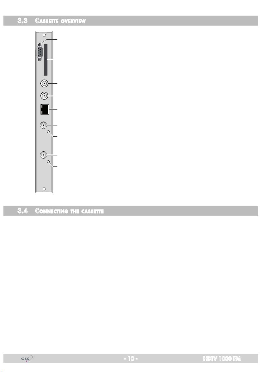
3.3 Cassette overview ............................................................................ 10
3.4 Connecting the cassette..................................................................... 10
3.5 Retrofitting a CA module ................................................................... 11
4 The control panel at a glance ...........................................................................12
4.1 Menu items...................................................................................... 12
4.2 Control panel................................................................................... 12
5 Programming ..................................................................................................13
5.1
Programming procedure.........................................................................13
5.2 Programming the cassette.................................................................. 15
Selecting the cassette........................................................................ 15
Input parameters .............................................................................. 16
LNB oscillator frequency .............................................................. 16
Input symbol rate ........................................................................ 17
DVB mode.................................................................................. 17
Setting the input frequency ........................................................... 18
Operation with a CA module ....................................................... 19
PID monitoring............................................................................ 19
CA module................................................................................. 19
Delete programme locations .............................................................. 21
Programme locations ........................................................................ 22
Submenus output parameters ............................................................. 22
Output frequency ........................................................................ 24
Channel selection........................................................................ 24
Language selection...................................................................... 25
Frequency deviation adjustment .................................................... 25
Kind of transmission .................................................................... 26
RDS........................................................................................... 26
Output level..................................................................................... 27
Factory reset.................................................................................... 28
Saving settings................................................................................. 28
6 Final procedures..............................................................................................29

- 3 - HDTV 1000 FM
1 safety regulations and notes
• Assembly, installation and servicingshould be carried out byauthorised
electricians.
• Switchofftheoperatingvoltageofthesystembeforebeginningwithassem-
bly or service work or pull out the mains plug.
• Donotperforminstallationandserviceworkduringthunderstorms.
• Installthesystemsoitwillnotbeabletovibrate…
- inadust-free,dryenvironment
- insuchamannerthatitisprotectedfrommoisture,fumes,splashingwa-
ter and dampness
- somewhere protected from direct sunlight
- not within the immediate vicinity of heat sources
- in an ambient temperature of 0 °C to +50 °C. In case of the formation of
condensation wait until the system is completely dried.
• Ensurethatthehead-endstationisadequatelyventilated.Donotcoverthe
ventilation slots.
• Bewareofshortcircuits
• Noliabilityisacceptedforanydamagecausedbyfaultyconnectionsor
inappropriate handling.
• Observetherelevantstandards,regulationsandguidelinesontheinstalla-
tion and operation of antenna systems.
• ThestandardsIEC/EN/DINEN50083resp.IEC/EN/DINEN60728must
be observed.
• For further information please read the assembly instructions for the head-
end station used.
• Test the software versions of the head-end station and the cassette and
update them if necessary. The current software versions can be found at
”www.gss.de”.
Take action to prevent static discharge when working on the device!
Electronic devices should never be disposed of in the household rubbish. In
accordance with directive 2002/96/EC of the European Parliament and the
European Council from January 27, 2003 which addresses old electronic and
electrical devices, such devices must be disposed of at a designated collection
facility. At the end of its service life, please take your device to one of these
public collection facilities for proper disposal.

- 4 - HDTV 1000 FM
2 general information
2.1 PaCking Contents
1 Cassette HDTV 1000 FM 2 HF cables
1 Brief assembly instructions
2.2 meaning of the symbols used
Important note
—> General note
• Performingworks
2.3 teChniCal data
The devices meet the following EU directives:
2006/95/EC,2004/108/EC
The product fulfils the guidelines and standards for CE labelling (see page 30).
Unless otherwise noted all values are specified as “typical”.
HF Input
Frequency range ........................................................ 925…2150MHz
Level range ............................................................. 60dBμV…80dBμV
Input impedance.............................................................................75 Ω
DVB-S modes .......................................... QPSK 1/2,2/3,3/4,5/6,7/8
DVB-S2 modes ...............QPSK1/2,3/5,2/3,3/4,4/5,5/6,8/9,9/10
8PSK3/5,2/3,3/4,5/6,8/9,9/10
Symbol rate DVB-S............................................. QPSK:2…45MSymb/s
Symbol rate DVB-S2......................................... QPSK:10…30MSymb/s
8PSK:10…31MSymb/s
HF output
Frequency range .......................................... 87.50MHz…108.00MHz
Tuning steps................................................................................50kHz
Type of modulation ............................................................................ FM
Return loss ......................................................................................8 dB
Output level .............................................................................. 93 dBμV
Signal-to-harmonics ratio ..............................................................>60 dB

- 5 - HDTV 1000 FM
Output impedance..........................................................................75 Ω
External voltage difference
Mono........................................................................................66 dB
Stereo .......................................................................................53 dB
Non-linear distortion factor
Mono.......................................................................................0,06%
Stereo ........................................................................................0,6%
Overall output frequency deviation ................................................75kHz
FM modulator
Number of available services (programme locations) ..............................12
RDS signal processing..................................................................................57kHz
Pilot signal..................................................................................................19kHz
Preemphasis.................................................................................................. 50 μs
ASI-Schnittstelle
Standard
........................................................................DIN EN 50083-9
Format ...............................................................MPEG ISO IEC 13818-1
Impedance
......................................................................................75 Ω
User data rate..................................................................2…90Mbit/s
Level ...................................................................................... 800 mVPP
Return loss .........................................................>17dB(5…270MHz)
Anschlüsse
SAT inputs.............................................................................2 F-Buchsen
HF output............................................................................ 1 IEC-Buchse
ASI input .......................................................................... 1 BNC-Buchse
Connection strip ........................................................................... 10-pin
For supply voltages and control circuits
Update interface............................................................... Buchse RS 232
Common Interface ................................................................................1
Several channels can be descrambled
Remote maintenance
Remotely controllable (via PSW 1000*): ..............................................yes
Remote update (via BEflash*):.............................................................yes
(* and a corresponding management unit)

- 6 - HDTV 1000 FM
2.4 desCriPtion
The cassette converts 12 stereo audio channels from two DVB-S /DVB-S2 stand-
ard modulated transponders and the ASI input signal into 12 FM modulated
stereo output channels.
The RDS station code is automatically taken from the station name of the trans-
ponder or can be entered manually.
Via SAT input A and a corresponding CA module scrambled channels can be
descrambled.
Principle signal path:
HF output
TS A
SAT input ”A“ Receiving stage
"A" CA module
ASI input
TS ASI
SAT input ”B“ Receiving stage
"B"
TS B
Combiner
12 fold modulator
TPS
The cassette is controlled with the head-end station control unit.
Two LEDs indicate by their colour the quality of the input signals (see figure on
page 10).10).).
LED indicator Indication
Green Signal quality is good
Yellow Signal quality is poor
Red No signal
To operate this cassette the software version of the control unit must be “V44”
or higher. You can find the current operating software for the control unit and
thecassette,thesoftware“BE-Flash”andthecurrentassemblyinstructionson
the website “www.gss.de”.
The cassette is designed for use in head-end stations of the standard line.

- 7 - HDTV 1000 FM
2.5 software query
Control unit
If necessary, you can activate the indication of the software version of the
control unit manually:
• Pressanytwokeysonthecontrolunitofthehead-endstationsimultaneously
untilthedisplaygoesdarkandthesoftwareversion,e.g.“V44”appears.
Cassette
After activating the cassette the software version of the cassette is displayed
(see page 15).

- 8 - HDTV 1000 FM
3 assembly
3.1 installing the Cassette
– Ensure the head-end station is mounted so it will not be able to vibrate.
Avoid,forexample,mountingthehead-endstationontoaliftshaftorany
other wall or floor construction that vibrates in a similar way.
– Before installing or changing a cassette unplug the power cable from the
mains power socket.
• Removethefasteningscrews1of an unoccupied slot from the bracket of
the head-end station.
• Insertthecassetteinthisslotandpushitintothehousing.
• Alignthecassetteandapplyslightpressuretoconnectittotheconnections
of the board and the HF bus bar.
• Fastenthecassettewiththescrews1.
CASSETTE
CASSETTE
CASSETTE
CASSETTE
CASSETTE
CASSETTE
CASSETTE
CASSETTE
CASSETTE
CASSETTE
CASSETTE
CASSETTE
MESSAUSGANG
A
CLASS
KLASSE
ACHTUNG!
Vor dem Cassettenwechsel
unbedingt Netzstecker ziehen!
CAUTION!
Before changing cassettes remove
mains plug!
0°
1
1

- 9 - HDTV 1000 FM
3.2 emC regulations
To comply with the current EMC regulations, it is necessary to connect the lines
leading in and out of the head-end station using cable terminals.
When mounting the cassette in a head-end station which is installed in a 19”
cabinet, make sure the connections leading in and out for the 19” cabinet are
made using cable terminals.
CLASS
KLASSE
The attenuation of shielding of the connection lines for ASI and antenna must
meet the requirements for “Class A”.
• Inserttherequirednumberofcableterminalsintheopeningsprovidedin
the head-end station or in the 19
”
cabinet.
Tighten the nuts on the cable terminals until the teeth on the lock washer have
penetrated the exterior coating and a good connection is made between the hous-
ing and cable terminals.

- 10 - HDTV 1000 FM
3.3 Cassette overview
1
2
3
4
5
6
7
8
9
1D-SUB socket “RS 232“
2 Slot for CA module
3 not used
4 ASI input
5 not used
6 SAT input (tuner “A”)
7 Status LED of input “A”
8 SAT input (tuner “B”)
9
Status LED of input “B”
The operating software of the cassette can be updated via the
9-pin D-SUB socket “RS 232” using a PC or notebook and the
software “BE-Flash”. You can find the current operating software
on the website
“www.gss.de”.
3.4 ConneCting the Cassette
• ConnecttheSATinputsockets“A”(tuner“A”)and“B”(tuner“B”)tothecor-
responding output sockets of the input distributor.
Use a 6dB attenuator for a direct connection without the input distributor.
• ConnecttheASIsocket.
• Connectthehead-endstationtothemains.

- 11 - HDTV 1000 FM
3.5 retrofitting aCa module
The cassette is equipped with a common interface. It allows you to connect a
CA module for various scrambling systems and service providers. Scrambled
stations can only be descrambled with a CA module suitable for the scram-
bling system and the corresponding smart card. The smart card contains all
theinformationforauthorisation,descramblingandsubscription.
Caution
– Check with the distributor or manufacturer of the CA module to be used to
ensure that it is suitable for descrambling several channels.
– Any changes made by programme providers to the structures in the pro-
gramme data might impair or even prevent this function.
– WhenworkingwiththeCAmodule,pleasereadthecorrespondingoperat-
ing manual from the respective provider.
• InsertthesmartcardintotheCAmodulesothatthechip3on the smart
card 1faces the thicker side (top) of the CA module 2.
• InserttheCAmoduleintotheslot4with the top side of the CA module
facing the RS-232 socket of the cassette.
• PushtheCAmodulewithoutcantingintotheguiderailsoftheCAslot4
and contact it to the common interface.
34 12

- 12 - HDTV 1000 FM
4 the Control Panel at aglanCe
4.1 menu items
Programme the
cassette
using the buttons on the control unit of the head-end
station. The two-line display of the control unit then shows the menus.
The parameters and functions to be set are underlined.
Use the key to select the following main menu items:
– Input parameters
– Deleting services (programme locations)
– Output parameters
– Output level
– Factory reset
4.2 Control Panel
The key pad on the head-end station is used to scroll through the menus:
scrolls forward through the menus.
select parameters in the menus.
setvalues,initiateactions.
selects sub-menus.
scrolls backward through the menus.
saves all entries.
BE-Remote V44
please wait . . .

- 13 - HDTV 1000 FM
5 Programming
5.1
Programming ProCedure
nur mit CA-Modul
nur Tuner A /
only with CA module
only tuner A
*) Die angezeigte Information ist abhängig
vom verwendeten CA-Modul.
The information displayed is dependent
on the CA module used.
Bx 4A 01/05
Information *)
MENU
Bx 4A
PID Check on
CA-MENU
=>
▶
▶
▶
Ein / On
BE–Remote
please wait …
V 44
Box 4
V 1
DVBS2-FM
– – –
Bx 1A
C5-12,S3-24
TWIN-SAT
C07
Böx 4
C5-12,S3-24
TWIN-SAT
C07
Box 5
..............
..............
..............
Bx 4
TunerA
INPUT
OK =>
B
t > 10 s
FM 01
Bayern 1
87.50
=>
Bx 4
LEVEL
0 dB
A
Bx 4A/B
10600 MHz
LNB
FM 01
87.50
FREQ
=> auto
Senderauswahl
Station selection
Tuner A /
Tuner B /
ASI
Bx 4A/B
27500
SYMBOL
DVB–S
Bx 4A/B
12265 +0.3
FREQ
CN 13
FM 01 RA
Bayern 1
001/091
Sprachauswahl
Language selection
FM 01
01/01 ger
AUDIO
Hubanpassung
Deviation adjustment
FM 01
0.0 dB
VOLUME
<=>C
FM 01 AUDIO
AUTO
FM 01
Bayern 1
RDS-NAME
=> auto
0 … - 10 dB
Bx 4
FM =>
SERVICES
CLEAR ALL
▶
▶
Box …
………
……
……
DVB-S / QPSK… /
8PSK… / DTV…
AUTO / MONO / STEREO
M
B
A
▶
Bx 4
Defaults
FACTORY
=>
Bx 4
STORE
FACTORY
=> M
auf Werkseinstellung
zurücksetzen und speichern
reset to factory defaults
and store
9750 / 10600
22000 / 27500
FM 01…12
FM 12…01
FM 01…12
FM 12…01
FM 01…12
FM 12…01
FM 01…12
FM 12…01
FM 01…12
FM 12…01
FM 01…12
FM 12…01
FM 01…12
FM 12…01
<zu klein too small
=OK
>zu groß too big
CBegrenzung clipping
Bedienhinweise
"blättert" Menüs vorwärts.
"blättert" Menüs rückwärts.
wählen die Eingabeposition
wählt Untermenü
stellen Werte ein,.
speichert alle Eingaben.
1zeigt die Eingabeposition
Operating Hints
scrolls forward through the menu.
scrolls backward through the menu.
select the enter position.
selects a submenu.
set values and triggers actions.
saves all entries.
1shows the enter position
page 14

- 14 - HDTV 1000 FM
nur mit CA-Modul
nur Tuner A /
only with CA module
only tuner A
*) Die angezeigte Information ist abhängig
vom verwendeten CA-Modul.
The information displayed is dependent
on the CA module used.
Bx 4A 01/05
Information *)
MENUBx 4A
PID Check on
CA-MENU
=>
▶
▶
▶
Ein / On
BE–Remote
please wait …
V 44
Box 4
V 1
DVBS2-FM
– – –
Bx 1A
C5-12,S3-24
TWIN-SAT
C07
Böx 4
C5-12,S3-24
TWIN-SAT
C07
Box 5
..............
..............
..............
Bx 4
TunerA
INPUT
OK =>
B
t > 10 s
FM 01
Bayern 1
87.50
=>
Bx 4
LEVEL
0 dB
A
Bx 4A/B
10600 MHz
LNB
FM 01
87.50
FREQ
=> auto
Senderauswahl
Station selection
Tuner A /
Tuner B /
ASI
Bx 4A/B
27500
SYMBOL
DVB–S
Bx 4A/B
12265 +0.3
FREQ
CN 13
FM 01 RA
Bayern 1
001/091
Sprachauswahl
Language selection
FM 01
01/01 ger
AUDIO
Hubanpassung
Deviation adjustment
FM 01
0.0 dB
VOLUME
<=>C
FM 01 AUDIO
AUTO
FM 01
Bayern 1
RDS-NAME
=> auto
0 … - 10 dB
Bx 4
FM =>
SERVICES
CLEAR ALL
▶
▶
Box …
………
……
……
DVB-S / QPSK… /
8PSK… / DTV…
AUTO / MONO / STEREO
M
B
A
▶
Bx 4
Defaults
FACTORY
=>
Bx 4
STORE
FACTORY
=> M
auf Werkseinstellung
zurücksetzen und speichern
reset to factory defaults
and store
9750 / 10600
22000 / 27500
FM 01…12
FM 12…01
FM 01…12
FM 12…01
FM 01…12
FM 12…01
FM 01…12
FM 12…01
FM 01…12
FM 12…01
FM 01…12
FM 12…01
FM 01…12
FM 12…01
<zu klein too small
=OK
>zu groß too big
CBegrenzung clipping
Bedienhinweise
"blättert" Menüs vorwärts.
"blättert" Menüs rückwärts.
wählen die Eingabeposition
wählt Untermenü
stellen Werte ein,.
speichert alle Eingaben.
1zeigt die Eingabeposition
Operating Hints
scrolls forward through the menu.
scrolls backward through the menu.
select the enter position.
selects a submenu.
set values and triggers actions.
saves all entries.
1shows the enter position
Seite 13

- 15 - HDTV 1000 FM
5.2 Programming the Cassette
—> Pressing the button for longer than 2 seconds cancels the
programming procedure. This takes you back to the program item
“Selecting the cassette” from any menu. Any entries that have not
been saved are reset to the previous settings.
—> Entries in the menus can be saved by pressing the key. You are
taken back to the “Selecting the cassette” menu item.
—>
Pressing the
button returns to the previous menus.
• Switchonthehead-endstation
Ein / On BE–Remote
please wait …
V 44
t > 10 s
—> The display shows the software version (e.g. V 44)
—> The processor reads the
cassettes
‘ data (approx. 10 seconds).
seleCting the Cassette
Box 4
V 1
DVBS2-FM
– – –
Bx 1A
C5-12,S3-24
TWIN-SAT
C07
Böx 4
C5-12,S3-24
TWIN-SAT
C07
Box 5
..............
..............
..............
Box …
………
……
……
• Selectthe
cassette
you want to program (e.g. Box 4) by repeatedly pressing
the button if necessary.
—>
The display shows e.g. the menu "Box 4 DVBS2-FM":
"Box 4" stands for
slot
4,
"
DVBS2-FM
" type of cassette
"V 1" software version of the cassette
• Pressthe button.
—> The
"
Input parameters
"
– "INPUT"
main menu is activated
.

- 16 - HDTV 1000 FM
inPut Par a meters
Inthismenuyouselecttheinput,forwhichyouwouldliketosettheinputpa-
rameters in the submenus.
Bx 4
TunerA
INPUT
OK =>
—> The indication “OK” serve for information:
OK - input signal is present at tuner A.
• Usethe
buttons to select the input
(
“
Tuner A
” / “
Tuner B
”/ "ASI"),
for which you would like to set the input parameters.
—> There are no input parameter settings for the ASI input.Select"ASI",
in order to check whether a ASI input signal is present ("OK" is
displayed).
—> To skip the settings of the input parameters press the but-
ton. The “Delete programme locations” – “SERVICES” main menu is
activated (page 21).
• Pressthe button.
—>
The “LNB oscillator frequency” – “LNB” submenu is activated.
lnb osCillator frequenCy
Set the oscillator frequency of the LNB used in this menu.
Bx 4A/B
10600 MHz
LNB
• Usingthe button the oscillator frequencies ”10600“ or ”9750“
can be selected directly.
• Tosetotheroscillatorfrequenciesusethe buttons to place the cursor
under the digit of the oscillator frequency displayed to be set.
• Press to enter the respective digit of the oscillator frequency of the
LNB used.
• Repeattheprocedurebythequantityofthedigitstobeset.

- 17 - HDTV 1000 FM
• Pressthe button.
—> The“Inputsymbolrate,DVBmode”–“SYMBOL” menu is activated.
inPut symbol r ate
dvb mode
The symbol rates of the satellite transponders can be found in the current chan-
neltableof the satelliteoperator,invarioussatellitemagazines and inthe
Internet.
ThecassetterecognizesthetransmittedDVBmodeandswitchesoverbetween
the normal QPSK mode (DVB-S) and the DVB-S2 mode. Receiving stations with
DVB-S2mode,wesuggesttopresettheDVBmodemanuallytoshortenthe
time for searching stations.
Bx 4A/B
27500
SYMBOL
DVB–S
Setting the input symbol rate
• Usingthe button the symbol rates 27500“ or ”22000“ can be
selected directly.
• Tosetothersymbolratesusethe buttons to position the cursor under
the digit of the symbol rate displayed to be set.
• Press
to enter the respective digit of the symbol rate needed.
• Repeattheprocedurebythequantityofthedigitstobeset.
Setting the DVB mode
• Usethe button to place the cursor under “DVB-S” and set the required
DVB-S2-mode with the
buttons.
• Pressthe button.
—> The “Setting the input frequency” – “FREQ” menu is activated.

- 18 - HDTV 1000 FM
setting the inPut frequenCy
If three dots “ …“appearinthesecondlineofthedisplay,thecassetteisin
the “station search” mode. Please wait until the process has finished.
OncetheHFreceiverhassynchronisedtotheinputsignal,anyoffsettothe
targetfrequencyisdisplayedinMHz,e.g.“+0.3”.
If a question mark “?”appearsinthesecondlineofthedisplay,thereisno
input signal present. Check the configuration of the antenna system and head-
end station as well as the preceding settings of the cassette.
Bx 4A/B
12265 +0.3
FREQ
CN 13
• Usethe buttons to position the cursor under the digit of the frequency
displayed to be set.
• Press
to set the input frequency.
• Set the frequency offset shown in the display
(e.g. “+ 1.3”)
to less than
1.0MHz
by varying the input frequency
using the
buttons.
—> The ”CN 13” display indicates the signal to noise ratio of the signal
received.
—> Ifstationsareselected,thequalityofthereceivedtransportstream
(level and C/N) is indicated by a status LED.
1
2
3
4
5
6
7
8
9
7Status LED Tuner A
9Status LED Tuner B
LED indicator Indication
Green Signal quality is good
Yellow Signal quality is insufficient
Red No signal
• Pressthe button.
—> Using a CA-Modul, submenu“
CA settings
” – “CA-MENU” is acti-
vated.
—> Not using a CA-Modul you will be r
eturned to the
“Input parameter”
– “INPUT”
main menu (page 16).

- 19 - HDTV 1000 FM
oPeration with aCa module
Inordertodescramblescrambledchannels,acorrespondingCAmoduleis
needed.
Pid monitoring
Ca module
In this menu you can switch off the PID monitoring and configuring the CA
module (dependent on the CA module).
Bx 4A
PID Check on
CA-MENU
=>
PID monitoring
By default the PID monitoring is switched on.
If particular PIDs are not descrambled the CI module is reset. Additionally
dropouts may occur if several stations are descrambled. To prevent this the PID
monitoring can be switched off.
Bx 4A
PID Check on
CA-MENU
=>
• Usethe buttons to switch “off” or “on” the PID monitoring.
Configuring the CA module
• Usethe button to activate the menu of the CA module.
The menu varies according to which CA module you are using. For this rea-
son,pleaserefertotheoperatingmanualofyourparticularCAmodule.The
relevant information is shown in the display of the head-end station. This may
appear as a fixed display or as scrolling text according to display capabilities.
Bx 4A 01/05
Information *)
MENU
Bx 4A
PID Check on
CA-MENU
=>
▶
▶

- 20 - HDTV 1000 FM
—> The display shows e.g.: Bx 4 01/05 MENU
Information
Meaning of the indicators:
“Bx 4” Slot 4
“
01/05
” The first of five menu items is activated.
“
MENU
” The menu of the CA module is activated.
For the explanation of further details please use the operating instructions of
the CA module used.
• Usethe buttons to activate the menu desired.
• Pressthe button to activate the menu.
• Usethe buttons to select the function desired.
• TosettheCAmoduleusethe and buttons.
• Allsettingsaresavedbypressingthe button.
—> You will be returned to the “PID monitoring” – “CA” main menu.
—> By pressing the button you can cancel the settings in the
menu of the CA module and are returned to the “PID monitoring” –
“CA” main menu.
• Pressthe button.
—> You will be r
eturned to the
“Input parameter” – “INPUT”
main menu
(page 16).
• Pressthe button.
—> The menu “Delete programme locations” – “SERVICES” is activated.
This manual suits for next models
1
Table of contents
Other GSS Modulator manuals

GSS
GSS HDMC 1000 FM User manual

GSS
GSS HDTV 1000 TD User manual

GSS
GSS HMM 470 User manual

GSS
GSS HD2CT 860 C User manual

GSS
GSS HDMC 1000 T User manual

GSS
GSS HDMA 784 C ASI User manual

GSS
GSS PMDF 1000 User manual

GSS
GSS HDM 2380 P CI User manual

GSS
GSS HDMC 1000 C User manual

GSS
GSS HDTA 614 T ASI Installation guide

GSS
GSS HDMT 1290 User manual

GSS
GSS HDMT 1000 ASI LAN User manual

GSS
GSS STI 1932 CT User manual

GSS
GSS HDMT 263 User manual

GSS
GSS HDM 500 C User manual

GSS
GSS HDTV 610 CI TPS User manual

GSS
GSS HDTV 1000 ASI LAN User manual

GSS
GSS HDTV 1000 ASI LAN User manual

GSS
GSS PAMS 4000 User manual

GSS
GSS HDTA 614 C ASI User manual