Terrasat IBUC User manual

Intelligent Block Upconverter (IBUC)
Operation Manual
No part of this manual may be reproduced,
transcribed, translated into any language or
transmitted in any form whatsoever without
the prior written consent of
Terrasat Communications, Inc.
© Copyright 2006 Terrasat Communications, Inc.
O&M – 10770-0001
Revision A
235 Vineyard Court, Morgan Hill, CA 95037 Phone: 408-782-5911 Fax: 408-782-5912
www.terrasatinc.com
24-hour Tech Support: 408-782-2166

IBUC Operation Manual
Terrasat Communications, Inc.
Rev. A
ii
Table of Contents
______________________________________________________________________
1. Introduction
Overview ………………………………………………………………………1-1
Reference documents ............................................................................ 1-2
Furnished Items...................................................................................... 1-4
Storage Information................................................................................ 1-6
Warranty Information.............................................................................. 1-6
Warranty Policy ...................................................................................... 1-8
2. IBUC Systems: Description
Functional Description............................................................................ 2-1
System Configurations ........................................................................... 2-2
System Block Diagrams ......................................................................... 2-3
3. IBUC Systems: Component Descriptions
Intelligent Block Upconverter (IBUC)...................................................... 3-1
Low Noise Block Converter (LNB).......................................................... 3-4
Power Supply Units (PSUI) .................................................................... 3-5
Interface Unit (IFU) ................................................................................ 3-5
Software................................................................................................. 3-7
4. IBUC Systems: Installation and Setup
Unpacking .............................................................................................. 4-1
Installing the Outdoor Unit (ODU)........................................................... 4-1
Installing the Indoor IFU ......................................................................... 4-4
System Cabling Requirements............................................................... 4-5
Grounding............................................................................................. 4-12
System Alignment and Operation......................................................... 4-14
Final Checks......................................................................................... 4-16
5. IBUC Systems: Service and Maintenance
Service and Maintenance....................................................................... 5-1
Fault Isolation......................................................................................... 5-1
6. IBUC Systems: M&C Functions
Description of Operation......................................................................... 6-1
Multi-Function LED................................................................................. 6-1
Hand Held Terminal................................................................................ 6-2
Frequency Shift Key Link........................................................................ 6-4
RS 485 ................................................................................................... 6-5
TCP/IP.................................................................................................. 6-11
Embedded Web Pages......................................................................... 6-28
Power Measurement ............................................................................ 6-36

IBUC Operation Manual
Terrasat Communications, Inc.
Rev. A
iii
7. IBUC Redundant Systems
Introduction............................................................................................. 7-1
Description.............................................................................................. 7-1
Component Descriptions ........................................................................ 7-3
Installation and Setup............................................................................. 7-8
System Alignment and Operation......................................................... 7-21
Final Checks......................................................................................... 7-23
M&C Setup........................................................................................... 7-24
Service and Maintenance..................................................................... 7-32
M&C Functions..................................................................................... 7-35
Embedded Web Pages......................................................................... 7-57
8. Glossary
Glossary of Terms……………………………………………………………8-1
9. Component Specifications and Reference Drawings
C-Band IBUC Specifications................................................................... 9-2
Ku-Band IBUC Specifications................................................................. 9-4
Outdoor Power Supply Specifications .................................................... 9-6
Interface Unit Specifications…………………………………..……………..9-8
1+1 Protection System Specifications ……………………..……………..9-10
Reference Drawings:
5/10W C-band IBUC Outline Drawing, Waveguide Output
5/10W C-band IBUC Outline Drawing, N-Type Output
20/25W C-band IBUC Outline Drawing, N-Type Output
20/25W C-band IBUC Outline Drawing, Waveguide Output
40W C-band IBUC Outline Drawing, N-type Output
40/80W C-band IBUC Outline Drawing, Waveguide Output
2-8W Ku-band IBUC Outline Drawing
12W Ku-band IBUC Outline Drawing
16/20W Ku-band IBUC Outline Drawing
2-8W Full Ku-band IBUC Outline Drawing
16/20W Full Ku-band IBUC Outline Drawing
25-40W Full Ku-band IBUC Outline Drawing
C-band LNB Outline Drawing
Ku-band LNB Outline Drawing
400W PSUI Outline Drawing
700W PSU Outline Drawing
IFU Outline Drawing
C-Band 1+1 Outline Drawings (6 Sheets)
Ku-Band 1+1 Outline Drawings (4 Sheets)
RX 1+1 Interface Assembly Outline Drawing
PSUI, IDU, 200W, Dual Power Supply Outline Drawing

IBUC Operation Manual
Terrasat Communications, Inc.
Rev. A
iv
FIGURES
Figure 2-1 Low Power System Configuration ......................................... 2-3
Figure 2-2 High Power System Configuration......................................... 2-4
Figure 2-3 Low Power System Configuration with IFU........................... 2-5
Figure 3-1 IBUC Block Diagram ............................................................. 3-3
Figure 3-2 LNB Block Diagram............................................................... 3-4
Figure 3-3 IFU, Tx/Rx, Block Diagram.................................................... 3-6
Figure 4-1 IBUC Front Panel.................................................................. 4-5
Figure 4-2 PSUI Front Panel………………………………………………...4-8
Figure 4-3 IFU Back Panel………………………………………………... 4-10
Figure 6-1 IBUC Hand Held Terminal..................................................... 6-3
Figure 6-2 IBUC Hand Held Terminal Menu Tree................................... 6-4
Figure 6-3 Login Web Page.................................................................. 6-29
Figure 6-4 Alarm Status Web Page...................................................... 6-30
Figure 6-5 Transmit Status Web Page ................................................. 6-31
Figure 6-6 Transmit Config Web Page................................................. 6-32
Figure 6-7 Interface Config Web Page................................................. 6-33
Figure 6-8 System Config Web Page................................................... 6-34
Figure 6-9 Alarm Config Web Page...................................................... 6-35
Figure 6-10 Burst Power Measurement................................................ 6-37
Figure 7-1 IBUC Redundant System...................................................... 7-2
Figure 7-2 TX 1+1 Interface Module Block Diagram............................... 7-4
Figure 7-3 RX 1+1 Interface Module Block Diagram .............................. 7-6
Figure 7-4 TX 1+1 Interface Module Top View..................................... 7-12
Figure 7-5 RX 1+1 Interface Module Front Panel................................. 7-16
Figure 7-6 RX 1+1 Interface Module Back Panel ................................. 7-16
Figure 7-7 RX 1+1 Interface Module Side View.................................... 7-16
Figure 7-8 IBUC Hand Held Terminal................................................... 7-37
Figure 7-9 RX 1+1 Hand Held Terminal Menu Tree............................. 7-38
Figure 7-10 IBUC 1+1 M&C Web Page................................................ 7-57
Figure 7-11 RX 1+1 Login Web Page................................................... 7-58
Figure 7-12 Network Config Web Page................................................ 7-59
Figure 7-13 Alarm Config Web Page.................................................... 7-60
Figure 7-14 Threshold Config Web Page............................................. 7-61
Figure 7-15 Alarm Status Web Page.................................................... 7-62
Figure 7-16 Sensor Status Web Page.................................................. 7-63
Figure 7-17 Alarm Control Web Page................................................... 7-64
Figure 7-18 Redundant Control Web Page .......................................... 7-65
TABLES
Table 1-1 Reference Documents ........................................................... 1-2
Table 2-1 Transmit Frequency Plans...................................................... 2-1
Table 2-2 Receive Frequency Plans....................................................... 2-2
Table 4-1 IBUC Connector Schedule ..................................................... 4-6
Table 4-2 IBUC M&C Connector J2, Pin Assignments........................... 4-7

IBUC Operation Manual
Terrasat Communications, Inc.
Rev. A
v
Table 4-3 IBUC Power Connector J3 Pin Assignments.......................... 4-8
Table 4-4 PSUI Connector Schedule...................................................... 4-9
Table 4-5 PSUI AC Power Connector J1 Pin Assignments.................... 4-9
Table 4-6 PSUI DC Output Connector J2, Pin Assignments .................. 4-9
Table 4-7 PSUI Fan Connection Pin Assignments............................... 4-10
Table 4-8 IFU Connector Schedule...................................................... 4-10
Table 4-9 Recommended Test Equipment........................................... 4-14
Table 6-1 LED Alarms............................................................................ 6-2
Table 6-2 IBUC Data Packet Byte Configuration.................................... 6-6
Table 6-3 Table of BUC Commands....................................................... 6-7
Table 6-4 Response to BUC Commands 0x01, 0x02, 0x03,
0x04, and 0x08...................................................................... 6-8
Table 6-5 Response to BUC Commands 0x05, 0x06 (when Data
Byte 1 of command message =0x00).................................... 6-9
Table 6-6 Response to BUC Command 0x06 (when Data
Byte 1 of command message=0x01)..................................... 6-9
Table 6-7 Response to command 0x07.................................................. 6-9
Table 6-8 Response to command 0x09................................................ 6-10
Table 6-9 IBUC M&C Command Set.................................................... 6-12
Table 6-10 Alarm Flags........................................................................ 6-28
Table 7-1 1+1 Interface Module............................................................ 7-13
Table 7-2 RS232, HHT & Alarm Connectors J1 and J8 Pin
Assignments......................................................................... 7-14
Table 7-3 M&C Interface Connectors J2 and J4, Pin Assignments...... 7-14
Table 7-4 User Interface Connector J3, Pin Assignments.................... 7-15
Table 7-5 RX 1+1 Interface Module...................................................... 7-17
Table 7-6 User Interface Connector J1, Pin Assignments.................... 7-18
Table 7-7 Power Connectors J2 and J3, Pin Assignments................... 7-18
Table 7-8 “Y” Adapter Connector Schedule.......................................... 7-19
Table 7-9 Recommended Test Equipment........................................... 7-21
Table 7-10 RX 1+1 Command Set………………………………………...7-41
Table 7-11 Alarm Flags........................................................................ 7-56
Warnings
Failure to observe all Warnings and Cautions may result in personnel injury and/or
equipment damage not covered by the warranty.
Follow standard Electrostatic Discharge (ESD)
procedures when handling the Terrasat
Equipment.

IBUC Operation Manual
Terrasat Communications, Inc.
Rev. A
vi
Only factory-trained and – authorized technicians
may perform any internal maintenance.
Observe normal safety precautions when
operating, servicing, and troubleshooting this
equipment.
Use care when working with high voltages.
Take standard safety precautions with hand
and/or power tools
Ensure that it is safe to transmit prior to enabling
the transmission.
Cautions
Use care when lifting the Terrasat equipment to
avoid physical injury.
Maintain a clear airflow passage around the
PSU’s and the IBUC (front, back, and sides) for the
fan intake and exhaust.
Ensure that the IBUC heat sink has been mounted
so that the heat may escape.
AC transients and surges can cause data
transmission errors.
Warranty seals are designed to break upon
internal access. Access to the internal electronics
without written approval will void the warranty.

IBUC Operation Manual
Terrasat Communications, Inc.
Rev. A 1-1
Chapter 1 Introduction
____________________________________________________________________
Overview
This user manual is for use with the Terrasat Communications, Inc. C and Ku-Band
Intelligent Block Upconverters (IBUC’s), Power Supply Units (PSUI’s), Low Noise
Block Converters (LNB’s), associated Interface Units (IFU’s, Tx 1+1 and Rx 1+1)
and accessories supplied with IBUC systems.
Intelligent Block Upconverters (IBUC’s)
The C and Ku-Band IBUC’s block upconvert an L-Band IF to one of four C-Band
uplink frequencies or one of three Ku-band uplink frequencies. The rated power of
the IBUC is specified at P1dB at the output waveguide flange or N-type connector.
The IBUC comes in a single weatherproof housing suitable for antenna or feedhorn
mounting. Refer to Table 2-1 for available frequency plans and power levels.
The term “Intelligent Block Upconverter” refers to the advanced features and Monitor
and Control (M&C) capabilities of the IBUC product. The IBUC includes Automatic
Gain Control (AGC) and Automatic Level Control (ALC) features as well as internal
diagnostics. It also provides extensive monitoring and control through a menu of
software commands and alarms providing access to the numerous operating
parameters and features available in the unit. Access to features and M&C is
provided via several methods including: Hand held terminal, RS232, RS485, TCP/IP
and FSK link via the IFL cable. The IBUC is also fitted with a multi-function LED for
visual status indications.
Power Supply Units (PSUI’s)
The PSUI converts the universal AC input (100-240VAC) to 24 or 48 VDC,
depending on the option ordered, to power the IBUC. The power supply is available
in two versions: indoor rack-mount and outdoor types. The 200W hot-swappable
dual Power Supply (indoor rack-mount) is housed in a Standard 1RU (19 inches
rack) and powers Low Power Tx and Rx Redundant Systems. The outdoor PSUI
comes in a single weatherproof housing suitable for antenna mounting and can
power all of the Terrasat IBUC’s. There are three versions of the outdoor PSUI
available: 400W 24V, 400W 48V and 700W 48V (same Power Supply as 400W 48V
with external cooling fan in a fan housing).
Low Noise Block Converters (LNB’s)
The C and Ku-Band LNB’s block downconvert one of three C-Band downlink
frequencies or one of three Ku-band downlink frequencies to an L-Band IF. The
noise temperature of the LNB is specified in degrees Kelvin. The LNB comes in a

IBUC Operation Manual
Terrasat Communications, Inc.
Rev. A 1-2
single weatherproof housing suitable for antenna feedhorn mounting. Refer to Table
2-2 for available frequency plans and noise temperature ratings.
Interface Unit (IFU)
The IFU (Interface Unit) allows the integrator to multiplex a 10MHz reference, a DC
voltage (24V or 48V) for Low Power IBUC’s, as well as 24V DC supply for the LNB,
onto the IFL that connects the Modem to the IBUC and LNB. The IFU comes in a
variety of configurations to fulfill customer specific needs.
Interface for Redundant Systems (Tx 1+1 and Rx 1+1)
The Tx 1+1 Interface module is a passive unit. This module divides the FSK, 10MHz
reference and L-Band signals, as well as routes the Ethernet connection to the
IBUC’s through an Ethernet switch. It supports various interface connectors and
includes a bank of LEDs for visual indication of alarm conditions. The user interface
may be through any of the following: via web browser to embedded web pages,
TCP/IP through Telnet session, handheld terminal, RS232, RS485, as well as FSK
link to both IBUC’s.
The Rx 1+1 Interface is a separate outdoor Rx interface module that is powered by
the IBUC power supplies and performs all required functions for redundant operation
of LNB’s. No indoor controller is necessary. The user interface may be through any
of the following: via web browser to embedded web pages, TCP/IP through Telnet
session, handheld terminal, RS232, or RS485. It also includes a bank of LEDs for
visual indication of alarm conditions.
This manual provides information on:
•How to install, operate, maintain and troubleshoot the IBUC’s, Power Supply
Units, Interface Units and Redundant Systems.
•How to use the user interface protocols for remote monitor and control
capabilities of the IBUC and Redundant Systems.
Reference Documents
Table 1-1 Reference Documents
Earth station Standards
Intelsat IESS 309 Performance Characteristics for Intermediate Data Rate
Digital Carriers Using Convolutional Encoding and QPSK
Modulation
Eutelsat EESS 502 Minimum Technical and Operational Requirements for
Earth Stations Transmitting to a Eutelsat Transponder for
Non-Standard Structured Types of SMS Transmissions.

IBUC Operation Manual
Terrasat Communications, Inc.
Rev. A 1-3
Standard M.
ETS 300-332 Satellite Earth Stations (SES); Transmit–only or transmit-
and-receive Very Small Aperture Terminals (VSATs)
used for communications operating in the Fixed Satellite
Service (FSS) 6 GHz and 4 GHz frequency bands.
ETS 300-159 Satellite Earth Stations (SES); Transmit/receive Very
Small Aperture Terminals (VSATs) used for data
communications operating in the Fixed Satellite Service
(FFS) 11/12/14 GHz frequency bands.
ETS 300-160 Satellite Earth Stations (SES); Control and monitoring
functions for VSAT networks.
ETSI EN 301 428 Satellite Earth Stations and Systems (SES); Harmonized
EN for Very Small Aperture Terminal (VSAT); Transmit-
only, transmit/receive or receive only satellite earth
stations operating in the 11/12/14 GHz frequency bands
covering essential requirements under article 3.2 of the
R&TTE directive.
ETSI EN 301 443 Satellite Earth Stations and Systems (SES); Harmonized
EN for Very Small Aperture Terminal (VSAT); Transmit-
only, transmit-and-receive, receive-only satellite earth
stations operating in the 4 GHz and 6 GHz frequency
bands covering essential requirements under article 3.2
of the R&TTE Directive.
Environmental Standards
ETS 300 019-1-1 Equipment Engineering (EE): Environmental Conditions
and Environmental Tests for Telecommunications
Equipment. Part 1-1: Classification of environmental
conditions. Storage.
ETS 300 019-1-2 Equipment Engineering (EE): Environmental Conditions
and Environmental Tests for Telecommunications
Equipment. Part 1-2: Classification of environmental
conditions. Transportation.
ETS 300 019-1-4 Equipment Engineering (EE): Environmental Conditions
and Environmental Tests for Telecommunications
Equipment. Part 1-4: Classification of environmental
conditions. Stationary use at non-weather protected
locations.
EMC/EMI Standards
99/5/EEC The Radio and Telecommunications Terminal Equipment
Directive
EN 301 489-12 v1.2.1 Electromagnetic Compatibility and Radio Spectrum
Matters (ERM); Electromagnetic Compatibility (EMC)
standard for radio equipment and services; Part 12:
Specific conditions for Very Small Aperture Terminal,
Satellite Interactive Earth Stations operated in the
frequency ranges between 4 GHz and 30 GHz in the

IBUC Operation Manual
Terrasat Communications, Inc.
Rev. A 1-4
Fixed Satellite Services (FSS)
EN 55022A Measurement of Radio Disturbance Characteristics
EN 61000-3-2/3 Electromagnetic Compatibility (EMC)
Safety Standards
73/23/EEC The Low Voltage Directive
EN 60950-1 Information technology equipment – Safety -
Furnished Items
Intelligent Block Upconverters (IBUC’s)
•A C-band or Ku-Band Intelligent Block Up-Converter (IBUC) with an
integrated SSPA
•Operating Manual in CD-ROM format
•WG Gaskets and Hardware (WG Units Only)
•Mounting Bracket (optional)
•Mounting Bolts
•Test datasheet and Certificate of Conformance
•Quick Setup Guide
Power Supply Units (PSUI’s)
•Indoor PSUI:
•A Single or Dual 200W Indoor Power Supply Unit (PSUI)
•A mating DC connector for the indoor PSUI
•Mounting Hardware
•AC Cable
•Spare Fuses
•Outdoor PSUI:
•A 400W Power Supply Unit
•A DC cable to interconnect to IBUC
•Mounting Bracket (optional)
•Mounting Bolts
•Mating AC Connector
•Spare Fuses
•A 700W Power Supply Unit
•A DC cable to interconnect to IBUC
•Mounting Bracket (optional)

IBUC Operation Manual
Terrasat Communications, Inc.
Rev. A 1-5
•Mounting Bolts
•Mating AC Connector
•Spare Fuses
Low Noise Block Converters (LNB’s)
•A C-band or Ku-band LNB (optional)
•WG Gasket and Hardware
Interface Unit (IFU)
•An Interface Unit
•Mounting Hardware
•AC Power Cord
•Spare Fuses
Redundant Systems (Tx 1+1 and Rx 1+1)
•A 1+1 Tx Interface Module
•A Waveguide Switch and WG pieces (C-band or Ku-band)
•Mounting plate with brackets (optional)
•BUC Interface cables (L-Band and M&C)
•Switch cable
•Power Supply Mounting Kit (optional)
•M&C Mating Connector
•Operating Manual in CD-ROM format
•Quick Setup Guide
•A 1+1 Rx Interface Module
•A Waveguide Switch (C-band or Ku-band)
•WG Pieces for Ku-band LNB Mounting
•M&C Mating Connector
•Mounting Bracket & Bolts
•Mounting Plate (optional)
•DC Cables and Y-cable Adapter (optional)
•L-Band cables
•Switch cable
•Operating Manual in CD-ROM format
•Quick Setup Guide
Accessories
•A handheld terminal (optional)

IBUC Operation Manual
Terrasat Communications, Inc.
Rev. A 1-6
•A TX reject filter - attached to the LNB (optional)
•A waveguide RX reject filter (optional)
•TCP/IP test cable (optional)
•Installation kits (optional)
Storage Information
•There are no storage limitations on the IBUC, outdoor PSUI or 1+1 Interfaces
for Redundant Systems other than avoiding excessive exposure beyond the
-40°C to +60°C external ambient temperature, as stated in Chapter 9,
Environmental Conditions.
•There are no storage limitations on the indoor PSUI’s or IFU’s other than
avoiding excessive exposure beyond the 0°C to +50°C external ambient
temperature, as stated in Chapter 9, Environmental Conditions.
Warranty Information
•All equipment warranty shall be in accordance with the Terrasat
Communications, Inc. Warranty Policy. See page 1-8.
•Returned Material Authorization (RMA)
•If any equipment is determined to be defective:
•Have available the following information:
•Unit serial number
•Unit part number and description
•Complete description of the failure
•Designated contact name and phone number
•Billing information
•Shipping information
•Contact Terrasat Customer Service to request a RMA number. The
phone number is listed on the front cover of this manual.
•Properly package the defective equipment in its original container (if
available and undamaged), and mark the RMA number on the outside
of the shipping container.

IBUC Operation Manual
Terrasat Communications, Inc.
Rev. A 1-7
•Ship the equipment to the address shown on the front cover of this
manual.
•After the unit is received at Terrasat, an initial evaluation will be
performed.
•If the unit is found to be in-warranty, the unit will be repaired and
returned at no charge.
•If the unit is found to be out-of-warranty, Terrasat Customer Service
will contact the designated contact for authorization to proceed with the
repair.
•Authorization in the form of a purchase order will be required.
•Once authorization is received, the unit will be repaired and returned.

IBUC Operation Manual
Terrasat Communications, Inc.
Rev. A 1-8
TERRASAT COMMUNICATIONS, Inc.
PRODUCTS WARRANTY POLICY
(A) This warranty is for equipment of Terrasat Communications, Inc. The term “Terrasat” as used
throughout this warranty shall mean Terrasat Communications, Inc, if the equipment was
manufactured by Terrasat Communications, Inc.
(B) Terrasat warrants that its equipment will be free from defects in material or workmanship at the
time of shipment and that it will conform to applicable specifications.
•For all Satcom products, the buyer shall exercise any and all warranty claims within a period of
twenty four (24) months.
•For all Radio products, the buyer shall exercise any and all warranty claims within a period of
eighteen (18) months.
(1) The warranty does not apply to any part of a product if it has been altered, repaired or misused
in a way that, in the opinion of Terrasat, affects the reliability of, or detracts from the performance
of any part of the product, or if it is damaged as a result of the use of such part in or in connection
with equipment not previously approved by Terrasat.
(2) The warranty does not apply to any product or parts thereof if its serial number or the serial
number of any of its part has been altered, defaced, or removed.
(3) The warranty does not cover damages or losses incurred in transportation.
(4) The warranty does not cover replacement or repair necessitated by loss or damage resulting
from any cause beyond the control of Terrasat.
(5) The warranty does not include the furnishing of any labor involved or connected with the
removal and/or reinstallation of warranted equipment or parts on site, or any labor required to
diagnose the necessity for replacement or repair.
(6) IN NO EVENT SHALL TERRASAT BE LIABLE TO BUYER FOR ANY INDIRECT,SPECIAL OR CONSEQUENTIAL
DAMAGES OR LOST PROFITS ARISING FROM THE USE OF THE EQUIPMENT OR PRODUCTS,EVEN IF
TERRASAT HAS BEEN ADVISED OF THE POSSIBILITY THEREOF,OR FOR ANY INABILITY TO USE THEM EITHER
SEPARATED FROM OR IN COMBINATION WITH ANY OTHER EQUIPMENT OR PRODUCTS.
(C) TERRASAT’S WARRANTY,AS STATED HEREIN,IS IN LIEU OF ALL OTHER WARRANTIES,EXPRESSED,
IMPLIED,OR STATUTORY,INCLUDING THOSE OF MERCHANTABILITY AND FITNESS FOR A PARTICULAR PURPOSE,
AND TERRASAT NEITHER ASSUMES NOR AUTHORIZES ANY PERSON TO ASSUME FOR IT ANY OTHER OBLIGATION
OR LIABILITY TO ANY PERSON IN CONNECTION WITH THE SALE OR USE OF TERRASAT’S PRODUCTS.The buyer
shall pass on to any purchaser, lessees, or other user of Terrasat’s products, the aforementioned
warranty, and shall indemnify and hold harmless Terrasat from any claim or liability of such purchaser,
lessees, or user based upon allegations that the buyer, its agents, or employees have made additional
warranties or representations as to product preference or use.
(D) A fixed charge established for each product will be imposed for all equipment returned for warranty
repair and where the cause of failure cannot be identified by Terrasat.

IBUC Operation Manual
Terrasat Communications, Inc.
Rev. A 2-1
Chapter 2 IBUC Systems: Description
______________________________________________________________________
Functional Description
Outdoor Equipment
The Terrasat line of C-band and Ku-band Outdoor Units (ODU’s) consists of a range of
Intelligent Block UpConverters (IBUC’s), Power Supply Units for IBUC’s (PSUI’s), and
Low Noise BlockConverters (LNB’s) for use in satellite earthstations. The outdoor
equipment is designed to interface directly with an L-band satellite modem.
The Interfacility Link (IFL) between the ODU’s and the L-band modem utilizes 950 to
1750 MHz (L-Band) as the interface frequency. This approach allows transmission and
reception over the entire satellite band as opposed to a single transponder. The L-band
IFL also carries associated signals (10MHz, DC voltage, FSK) simplifying installation
and reducing costs. Terrasat IBUC’s are available in C-Band or Ku-band and can be
used for SCPC/MCPC, point-to-point, or point-to-multipoint network applications (voice,
data, video or IP services). All outdoor units are weatherized and designed to mount
outdoors, in most climates, and on most satellite earthstation antennas. Refer to Figures
2-1, 2-2 and 2-3 for typical equipment configurations.
The IBUC is available in Standard C-band, Palapa C-band, Insat C-band, Extended C-
Band, Standard Ku-band, Extended Ku-band, or Full Ku-band. See Table 2-1 for actual
frequencies. The IBUC houses the IF Interface (de-mux), the UpConverter (UPC), the
Monitor and Control (M&C) card, a DC to DC converter and associated circuitry, and a
Solid State Power Amplifier (SSPA) assembly. The 20-80 watt C-band IBUC’s and the
12-40 watt Ku-band IBUC’s also have an external cooling fan assembly. The input
interface to the IBUC interfaces to a 50 Ωor 75 Ω(optional) coaxial cable that carries
the L-Band transmit signal, 10 MHz reference oscillator signal, DC power and bi-
directional M&C FSK signals.
Table 2-1 Transmit Frequency Plans
Standard Palapa Insat Extended Standard Extended Full
Signal C-band C-band C-band C-band Ku-band Ku-band Ku-band
L-band 950-1525MHz 1150-1450MHz 1150-1450MHz 950-1750MHz 950-1450MHz 950-1450MHz 950-1700MHz
LO fr. 7.375GHz 7.875GHz 8.175GHz 7.600GHz 13.050GHz 12.800GHz 12.800GHz
RF fr. 5.850-6.425GHz 6.425-6.725GHz 6.725-7.025GHz 5.850-6.650GHz 14.00-14.50GHz 13.75-14.25GHz 13.75-14.50GHz
Output
Power 5,10,20,25,40,
60, 80W 5,10,20,25,40,
60, 80W 5,10,20,25,40,
60, 80W 5,10,20,25,40,
60, 80W 4,8,12,16,20,25,
30,40W 4,8,12,16,20,25,
30,40W 4,8,12,16,20,25,
30,40W
The LNB is available in Standard C-band, Palapa C-band, Insat C-band, or one of three
Ku-band frequency bands. See Table 2-2 for actual frequencies. The C-band LNB
comes standard with a typical noise temperature of 35oK whereas the Ku-band typical
noise temperature is 60oK. The LNB houses the Low Noise Amplifier (LNA), the RX
conversion circuitry, and the L-band IF Interface (de-mux). The interface with the LNB

IBUC Operation Manual
Terrasat Communications, Inc.
Rev. A 2-2
consists of a 50 or 75 Ω(optional) coaxial cable that carries the L-Band receive signal,
10 MHz reference oscillator signal, and DC power.
Table 2-2 Receive Frequency Plans
Standard Palapa Insat
Signal C-band C-band C-band Ku-band
RF fr. 3.625-4.200GHz 3.400-4.200GHz 4.500-4.800GHz 10.95-11.70GHz or
11.70-12.20GHz or
12.25-12.75GHz
L-band Out fr. 950-1525MHz 950-1750MHz 960-1260MHz 950-1700MHz or
950-1450MHz
Noise temperature 35°K 35°K 35°K 60°K
The PSUI converts the universal AC input (100-240VAC) to 24VDC or 48 VDC to
power the IBUC. The 400W outdoor PSUI comes in a single weatherproof housing
suitable for antenna mounting and can power 5-40W C-band and 4-25W Ku-band
IBUC’s. The 700W outdoor PSUI comes in a single weatherproof housing suitable for
antenna mounting. The 700W PSUI includes a cooling fan and a fan housing and can
power 60-80W C-band and 30-40W Ku-band IBUC’s.
Indoor Equipment
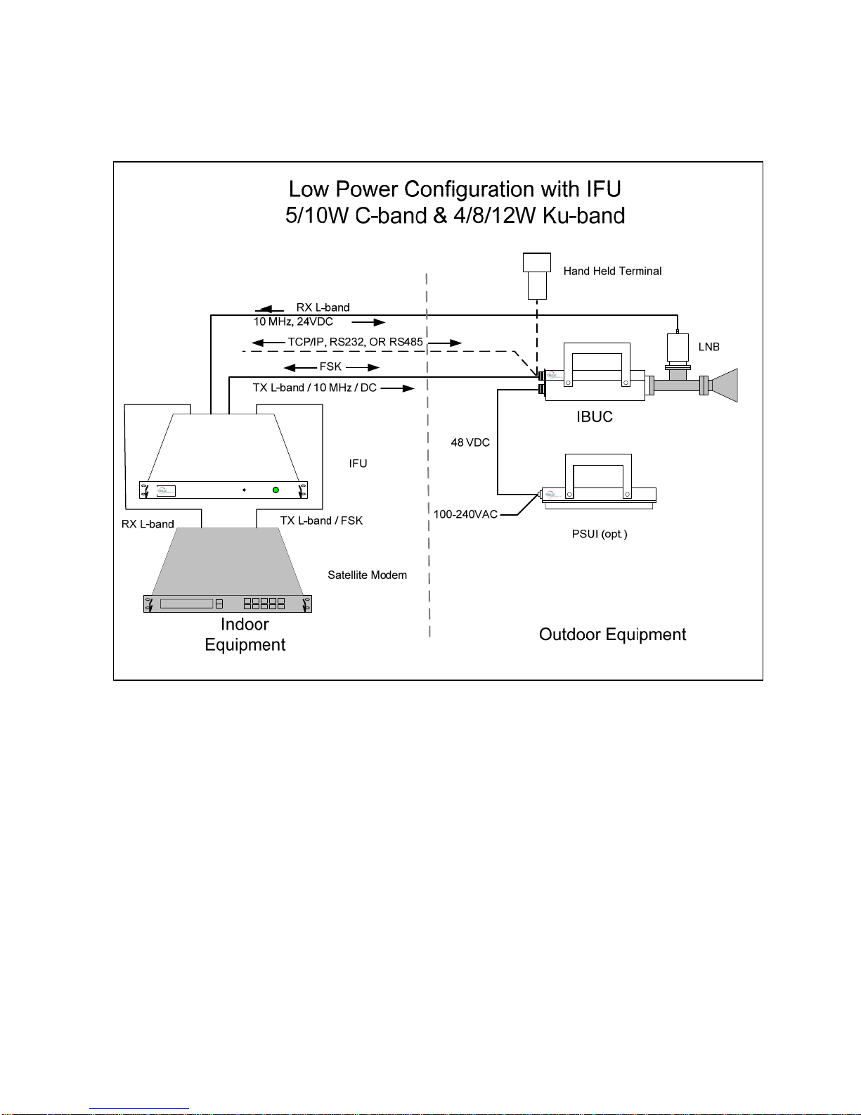
The indoor IFU (Interface Unit) allows the integrator to multiplex a 10MHz reference, a
DC voltage (24V or 48V) for Low Power IBUC’s (up to 12W Output Power), as well as
24V DC supply for the LNB, in case the Modem doesn’t offer these features. Any
combination can be configured at the factory; for example, IBUC Supply only, 10 MHz
reference only, both IBUC Supply and 10 MHz, etc. The IFU also provides a pass for
the FSK signal, allowing the Modem to communicate with IBUC. The IFU is housed in a
1RU rack mount (19 inches) and has to be connected between the Modem and the
IBUC and LNB.
System Configurations
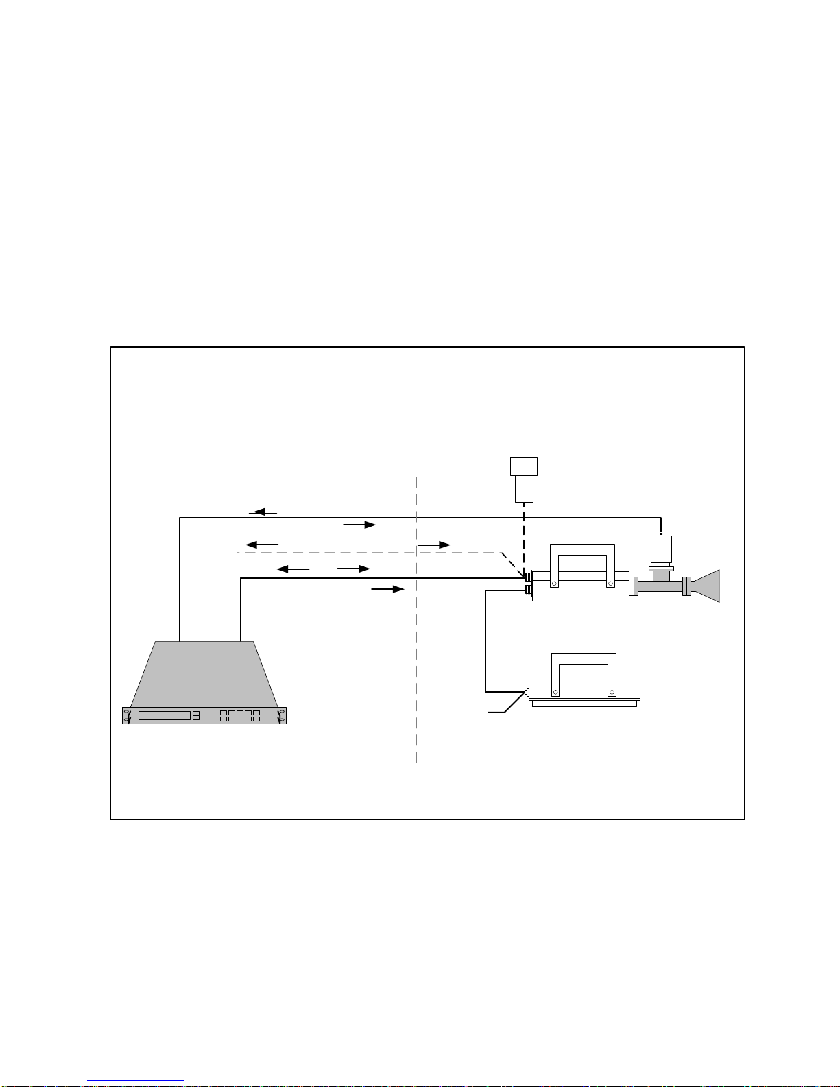
Figures 2-1, 2-2 and 2-3 show typical earth station installations using Terrasat
transceivers. In normal operation the IBUC, the LNB, and the PSUI are mounted
outdoors on the antenna. The IBUC and the LNB can interface directly to a satellite
modem, a 70MHz to L-band rackconverter, a modem combiner network, or an IFU. In
any case, the indoor unit must provide the 10MHz for the LNB and the IBUC, the DC
voltage for the LNB, and the TX L-band signal for the IBUC. The modem may supply the
DC voltage via the IFL cable to the IBUC (4-12Watt units). In addition, the indoor
equipment will receive the RX L-band signal from the LNB.
Monitor and Control (M&C) is available via an FSK signal (through the IFL) or through a
separate cable for either RS-232, RS-485 or TCP/IP. A Hand Held Terminal is available
for local M&C. Refer to chapter 6 for actual M&C capabilities and commands for the
IBUC.
IBUC Operation Manual
Terrasat Communications, Inc.
Rev. A 2-3
Certain considerations must be taken when selecting the IFL since appropriate shielding
and signal levels are required for normal system operation. The IBUC is designed to
operate with a –30 dBm TX L-band input signal to achieve rated power at maximum
gain. The IBUC provides a user accessible variable attenuator that allows the gain of
the unit to be reduced by up to 16dB in 0.1dB steps. The attenuator can be used to
prevent overdrive to IBUC in configurations with a short cable run (IFL) and thereby
preserving Modem dynamic range. In addition the IBUC and LNB must have a 10MHz
input signal, at +3 to -12 dBm for the IBUC, and 0 to –10 dBm for the LNB. The
maximum voltage drop for a 24VDC BUC is 4 volts and for a 48VDC BUC is 11 volts.
PSUI (opt.)
48 VDC
Indoor
Equipment Outdoor Equipment
Satellite Modem
Hand Held Terminal
IBUC
FSK
100-240VAC
TCP/IP, RS232, OR RS485
RX L-band
10 MHz, 24VDC
Low Power Configuration
5/10W C-band & 4/8/12W Ku-band
3
TX L-band / 10 MHz / DC
LNB
Note: 12W IBUC has a cooling fan
Figure 2-1 Low Power System Configuration

IBUC Operation Manual
Terrasat Communications, Inc.
Rev. A 2-4
Note: PSUI could be -548 or -648 (with cooling fan)
Figure 2-2 High Power System Configuration
IBUC Operation Manual
Terrasat Communications, Inc.
Rev. A 2-5
Note: 12W IBUC has a cooling fan
Figure 2-3 Low Power System Configuration with IFU

IBUC Operation Manual 3-1
Terrasat Communications, Inc.
Rev. A
Chapter 3 IBUC Systems: Component
Descriptions
_____________________________________________________________________
As described in earlier chapters the ODU consists of an Intelligent Block Upconverter
(IBUC) and could include a Power Supply Unit for IBUC’s (PSUI) and / or a Low Noise
Blockconverter (LNB). The indoor IFU may also be part of the configuration. This
chapter explains the functionality of each component and their interrelationships. Refer
to chapter 9 for the specifications of each of the components.
Intelligent Block Up-Converter (IBUC)
The IBUC is the heart of the Terrasat ODU. The IBUC comes in a variety of frequency
band and power level configurations. The IBUC is available in Standard C-band,
Palapa C-band, Insat C-band, Extended C-band, Standard Ku-band, Extended Ku-
band and Full Ku-band. The C-band IBUC is available in 5, 10, 20, 25, 40, 60, and 80
watt configurations. The Ku-band IBUC is available in 4, 8, 12, 16, 20, 25, 30 and 40
watt configurations. The IBUC houses the IF Interface (de-mux), the Upconverter
(UPC), the Monitor and Control (M&C) card, a DC to DC converter and associated
circuitry, and a Solid State Power Amplifier (SSPA) assembly. The 20-80 watt C-band
IBUC’s and the 12-40 watt Ku-band IBUC’s also have an external cooling fan
assembly. The interface with the IBUC is through a 50Ωor 75Ω(optional) coaxial cable
that carries the L-Band transmit signal, 10 MHz reference oscillator signal, DC power
and bi-directional M&C FSK signals. The IBUC also comes standard with an M&C port
for TCP/IP, RS-232, RS-485, and Hand Held Terminal access. The IBUC also provides
a status alarm output (Form-C relay). A multi-function LED is installed on the IBUC to
provide visual status indications.
Refer to the IBUC block diagram on page 3-3.
DC Supply
For lower power units (12W and below) DC power can be applied through the L-band
input N-connector or F-connector (J1) or through the external power connector (J3).
DC power for the higher power units (16W and above) is applied through the DC input
6-pin circular connector (J3). The high power units cannot accept the DC input through
the L-band input N-connector or F-connector (J1) due to the higher current draw. In all
cases the DC power input source is automatically sensed and protected so that an
input to one connector does not result in an output to the other connector. If for some
reason a DC power source is applied to both connectors simultaneously the protection
circuitry prioritizes which DC power source will be utilized. The priority connector is the
DC input 6-pin circular connector (J3).
Table of contents
Other Terrasat Media Converter manuals


Popular Media Converter manuals by other brands


H&B
H&B TX-100 Installation and instruction manual

Bolin Technology
Bolin Technology D Series user manual

IFM Electronic
IFM Electronic Efector 400 RN30 Series Device manual

GRASS VALLEY
GRASS VALLEY KUDOSPRO ULC2000 user manual

Linear Technology
Linear Technology DC1523A Demo Manual

Lika
Lika ROTAPULS I28 Series quick start guide

Weidmuller
Weidmuller IE-MC-VL Series Hardware installation guide

Optical Systems Design
Optical Systems Design OSD2139 Series Operator's manual

Tema Telecomunicazioni
Tema Telecomunicazioni AD615/S product manual

KTI Networks
KTI Networks KGC-352 Series installation guide

Gira
Gira 0588 Series operating instructions

Lika
Lika SFA-5000-FD user guide