Terrasat IBUC 2 User manual
Cyber Hardened Intelligent Block
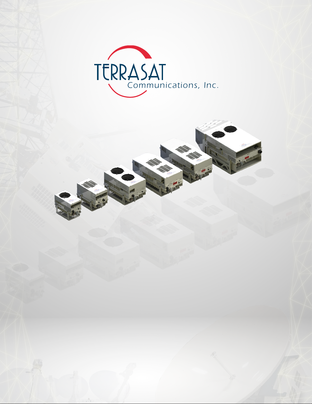
Upconverter
IBUC 2, IBUC 2e, IBUC 2G, IBUC R and IBUC G
Operations Manual
24-Hour Technical Support: +1 669.258.9740
Engineered t o Endure

This document is provided to customers who have purchased Terrasat Communications, Inc.
equipment. This document is copyright protected and no part of this manual may be reproduced,
transcribed, or translated into any language or transmitted in any form whatsoever without the
prior written consent of Terrasat Communications, Inc.
Technical information contained in this publication is for reference purposes only and is subject
to change without notice. Every effort has been made to supply complete and accurate
information; however, Terrasat Communications, Inc. assumes no responsibility and will not be
liable for any errors, omissions, damage, or loss that might result from any use of this manual or
the information contained therein (even if this information is properly followed and problems still
arise).
© October 2020 Terrasat Communications, Inc.
Part Number: O&M-22062-0003
Revision: B
315 Digital Drive Phone: +1 408.782.5911
Morgan Hill, CA 95037 FAX: +1 408.782.5912
www.terrasatinc.com

i
TABLE OF CONTENTS
Engineered t o Endure
Preface
Conventions and References .................................................................................................... P-1
Cautions and Warnings ..................................................................................................... P-2
Trademarks........................................................................................................................ P-2
Electrical Safety Notice .................................................................................................... P-2
Chapter 1, Introduction
Block Upconverters.................................................................................................................. 1-1
Reference Documents .............................................................................................................. 1-2
Warranty Information............................................................................................................... 1-5
Chapter 2, Functional Description
Introduction .............................................................................................................................. 2-1
System Components................................................................................................................. 2-2
DC Supply............................................................................................................................ 2-8
AC Supply............................................................................................................................ 2-8
Fuses..................................................................................................................................... 2-13
Monitor and Control............................................................................................................. 2-15
RF Signal Flow .................................................................................................................... 2-16
Software ............................................................................................................................... 2-22
System Configurations......................................................................................................... 2-23
Storage Information ............................................................................................................. 2-28
Chapter 3, Installation
Introduction .............................................................................................................................. 3-1
General Requirements.............................................................................................................. 3-1
Unpacking ......................................................................................................................... 3-1
Furnished Items................................................................................................................. 3-2
Accessories........................................................................................................................ 3-3
Installing the ODU ............................................................................................................... 3-3
Test Equipment ................................................................................................................. 3-4
Site Considerations ........................................................................................................... 3-4
Mounting Considerations.................................................................................................. 3-4
Power Requirements ......................................................................................................... 3-5
Grounding ......................................................................................................................... 3-7
Antenna Recommendations .............................................................................................. 3-7
Antenna Mounting ............................................................................................................ 3-8
System Pressurization ....................................................................................................... 3-12
System Cabling Requirements.......................................................................................... 3-13

ii
Engineered t o Endure
Cable and Waveguide Connections .................................................................................. 3-18
Basic System Alignment...................................................................................................... 3-20
Setting the Tx and Rx Frequencies ................................................................................... 3-21
Transmit Power Alignment............................................................................................... 3-21
Transmit RF Output Adjustment with Modem or Converter (70 MHz to L-band).......... 3-22
Final Checks............................................................................................................................. 3-23
Chapter 4, Operations
Introduction.............................................................................................................................. 4-1
Start-up Checklist..................................................................................................................... 4-1
Turning On the IBUC .......................................................................................................... 4-2
Setting Operating Parameters .............................................................................................. 4-2
Setting the Tx Frequency (L-band)................................................................................... 4-4
Setting Alarm Thresholds ................................................................................................. 4-4
Configuring Alarm States ................................................................................................. 4-5
Configuring ALC/AGC .................................................................................................... 4-5
Configuring the External Mute ......................................................................................... 4-6
Common Errors........................................................................................................................ 4-7
LED is Red........................................................................................................................ 4-7
No Power to the Cyber Hardened IBUC 2, IBUC 2e, IBUC 2G, IBUC R or IBUC G. 4-7
Time Stamp Data is Incorrect ........................................................................................... 4-8
Satellite Network Operations Center Doesn’t Recognize Signal ..................................... 4-8
Transmit Power in Saturation ........................................................................................... 4-9
Tx Input/Output Level Verification.................................................................................. 4-9
Chapter 5, Monitor and Control Features
Introduction.............................................................................................................................. 5-1
M&C Interfaces........................................................................................................................ 5-1
RS232................................................................................................................................... 5-1
Multifunction LED .............................................................................................................. 5-2
Ethernet................................................................................................................................ 5-3
Determining the IP Address of Your IBUC...................................................................... 5-4
SSHv2 ............................................................................................................................... 5-4
SNMPv3............................................................................................................................ 5-5
Embedded Web Pages ...................................................................................................... 5-7
Power Measurement................................................................................................................. 5-7
Input Power Overdrive Protection ....................................................................................... 5-8
Chapter 6, Troubleshooting
Maintenance ............................................................................................................................. 6-1
Transceiver Fault Isolation .................................................................................................. 6-1
AC Power Problems/Conditioning ................................................................................... 6-1
Site-Related Problems....................................................................................................... 6-2
M&C Checks .................................................................................................................... 6-2

iii
Engineered t o Endure
Power Supply Checks ....................................................................................................... 6-3
Transmit Power Setting .................................................................................................... 6-3
Common Problems .............................................................................................................. 6-5
Tx Output is Disabled ....................................................................................................... 6-5
Incorrect Frequency Settings ............................................................................................ 6-5
Damaged Cables ............................................................................................................... 6-5
10 MHz Reference Signal is at the Wrong Level or Missing........................................... 6-6
Antenna is Pointed Toward Wrong Satellite or is Misaligned ......................................... 6-6
Moisture Migrated Into the Cyber Hardened IBUC ......................................................... 6-7
Bad Orthogonal Mode Transducer and/or Antenna.......................................................... 6-7
LED is Red........................................................................................................................ 6-7
Repair Policy............................................................................................................................ 6-8
Returned Material Authorization (RMA) ............................................................................ 6-8
Appendix A, Part Numbering Schema
Identifying the Part and Serial Numbers.................................................................................. A-1
Decoding the Part Number....................................................................................................... A-1
Appendix B, Embedded Web Pages
Introduction.............................................................................................................................. B-1
Screen Shots............................................................................................................................. B-4
Log In................................................................................................................................ B-4
Responsive Design............................................................................................................ B-5
Information Tab ................................................................................................................ B-6
Alarm Tab ......................................................................................................................... B-8
Sensor Tab ........................................................................................................................ B-11
Transmit Configuration Tab ............................................................................................. B-12
Interface Configuration Tab.............................................................................................. B-16
System Configuration Tab ................................................................................................ B-17
Alarm Configuration Tab.................................................................................................. B-18
Charts ................................................................................................................................ B-21
Appendix C, ASCII Command/Response Structure
Cyber Hardened IBUC Console and SSHv2 Command Set.................................................... C-1
Appendix D, Component Specifications and Reference Drawings
Reference Drawings................................................................................................................. D-1
Data Sheets............................................................................................................................... D-7
Appendix E, Firmware Upgrade
Update Procedure..................................................................................................................... E-1


v
LIST OF TABLES
Engineered t o Endure
Table P.1 Typographical Conventions ........................................................................................ P-1
Table 1.1 Satellite Operation Standards...................................................................................... 1-2
Table 2.1 IBUC 2 Transmit Frequency Plans............................................................................. 2-3
Table 2.2 IBUC 2e Transmit Frequency Plans ........................................................................... 2-4
Table 2.3 IBUC 2G Transmit Frequency Plans ......................................................................... 2-5
Table 2.4 IBUC R Transmit Frequency Plans............................................................................ 2-6
Table 2.5 IBUC G Transmit Frequency Plans............................................................................ 2-7
Table 2.6 AC Supply Operating Voltage Ranges ....................................................................... 2-8
Table 2.7 Fuse Markings............................................................................................................. 2-13
Table 2.8 External 10 MHz Reference Signal Parameters.......................................................... 2-16
Table 2.9 Internal 10 MHz Reference Signal Parameters........................................................... 2-16
Table 2.10 Basic System Requirements........................................................................................ 2-23
Table 3.1 Recommended Test Equipment .................................................................................. 3-4
Table 3.2 Terrasat Outdoor Power Supplies ............................................................................... 3-6
Table 3.3 Interface Connector Schedule ..................................................................................... 3-13
Table 3.4 Pin Assignments for M&C Interface Connector J2 .................................................... 3-15
Table 3.5 Pin Assignments for DC Power Connector J3............................................................ 3-16
Table 3.6 Pin Assignments for AC Power Connector J3............................................................ 3-16
Table 3.7 Pin Assignments for Milspec High-Power AC Connector J3..................................... 3-17
Table 3.8 Pin Assignments for Ethernet Connector J4 ............................................................... 3-17
Table 5.1 Default Alarm Configuration...................................................................................... 5-3
Table 6.1 Possible Scenarios for IBUCs with an External 10 MHz Reference Signal............... 6-6
Table B.1 Default Values for Power Monitor Frequency............................................................ B-13
Table B.2 Default Values for Burst Threshold............................................................................ B-14
Table C.1 Error Response Table.................................................................................................. C-1
Table C.2 Alarm Mask ................................................................................................................ C-6
Table C.3 Configurable Alarm Mask .......................................................................................... C-14
Table C.4 Default Values for the TAH, TAL, and TBT Commands ..........................................C-37
Table C.5 Band Numbering......................................................................................................... C-38
Table C.6 Default Values for the TFR Command....................................................................... C-40

vi
Engineered t o Endure

vii
LIST OF FIGURES
Engineered t o Endure
Figure 2.1 Front Panel of a Low Energy Consumption IBUC 2e................................................... 2-9
Figure 2.2 Front Panel of a DC-powered IBUC 2............................................................................. 2-10
Figure 2.3 Front Panel of an AC-powered IBUC 2G................................................................. 2-11
Figure 2.4 Front Panel of an AC-powered IBUC G using MilSpec connector .......................... 2-12
Figure 2.5 IEC 127 Compliant Fuse Marking............................................................................. 2-15
Figure 2.6 DC-powered Low-Power Cyber Hardened IBUC Block Diagram............................ 2-19
Figure 2.7 DC-powered Cyber Hardened IBUC Block Diagram................................................ 2-20
Figure 2.8 AC-powered Cyber Hardened IBUC Block Diagram................................................ 2-21
Figure 2.9 DC Low Power IBUC System Configuration............................................................ 2-25
Figure 2.10 DC Power IBUC System Configuration .................................................................... 2-26
Figure 2.11 AC Power IBUC System Configuration .................................................................... 2-27
Figure 3.1 Furnished items with Cyber Hardened IBUC 2......................................................... 3-2
Figure 3.2 IBUC 2 Field Installation........................................................................................... 3-9
Figure 3.3 IBUC 2 Installation .................................................................................................... 3-10
Figure 3.4 Location of Mounting Holes...................................................................................... 3-11
Figure 3.5 IBUC In Line Mounting Configuration ..................................................................... 3-11
Figure 3.6 Location of Adjustment Slots on Optional Mounting Bracket .................................. 3-12
Figure 3.7 Connector J1 Caution Symbol ................................................................................... 3-14
Figure 3.8 Applying the Anti-Seize Lubricant ............................................................................ 3-19
Figure 3.9 Waveguide Label and Channel for Gasket ................................................................ 3-20
Figure A.1 Identifying the Part and Serial Numbers.................................................................... A-1
Figure A.2 Part Numbering Schema for Cyber Hardened IBUC................................................. A-2
Figure A.3 Part Numbering Schema for Cyber Hardened IBUC with PSUI Systems................. A-3
Figure B.1 Ethernet Properties Window ...................................................................................... B-2
Figure B.2 Choosing the Internet Protocol (TCP/IP) Properties ................................................. B-2
Figure B.3 Host IP Address Configuration.................................................................................. B-3
Figure B.4 Login Tab................................................................................................................... B-4
Figure B.5 Mobile view of the Embedded Web Pages ................................................................ B-5
Figure B.6 Information Tab ......................................................................................................... B-6
Figure B.7 Alarm Status Tab ....................................................................................................... B-8
Figure B.8 Sensor Tab ................................................................................................................. B-11
Figure B.9 Tx Configuration Tab ................................................................................................ B-12
Figure B.10 Interface Configuration Tab....................................................................................... B-16
Figure B.11 System Configuration Tab ......................................................................................... B-17
Figure B.12 Alarm Configuration Tab........................................................................................... B-18
Figure B.13 Statistics Charts.......................................................................................................... B-21
Figure D.1 Fabrication Drawing, FBD-21012-XXXX, Rev A.................................................... D-2
Figure D.2 Fabrication Drawing, FBD-21984-XXXX, Rev B, page 1 of 2 ................................ D-3
Figure D.3 Fabrication Drawing, FBD-21984-XXXX, Rev B, page 2of 2 ................................. D-4
Figure D.4 Fabrication Drawing, FBD-20606-XXXX, Rev A.................................................... D-5
Figure D.5 Example Installation Drawing, IND-10521-0011, Rev A ......................................... D-6

viii
Engineered t o Endure
Figure E.1 Firmware Upgrade File.............................................................................................. E-2
Figure E.2 Software Update Web Page ....................................................................................... E-2
Figure E.3 Software Update progress.......................................................................................... E-3
Figure E.4 Software Update Wait for Reboot ............................................................................. E-4
3
REVISION HISTORY
Engineered t o Endure
Revision Date Description
A 08/06/2020 Initial Public Release
B 10/09/2020
Added Appendix B, Embedded Web Pages
Updated Appendix C, ASCII Command Response Structure
Added Appendix E, Firmware Upgrade

4
Engineered t o Endure
PREFACE
P
This manual provides information about the Terrasat Communications, Inc. line of
cyber hardened intelligent block upconverters.
Conventions and References
Before you start using this manual, it is important to understand the typographical
conventions and terms used in the documentation.
Table P.1 describes typographical conventions used in Terrasat Communications, Inc.
documentation. For definitions of specialized terms used in the documentation, see
Appendix F, Glossary.
Table P.1
Typographical Conventions
Convention Description/Example
Emphasis
Used to emphasize the importance of a point.
The IP Address must be a unique number.
Internal cross-references
References to a section in the same document are marked in blue and
are hyperlinked.
See Warranty Information on page 1-5.
Product and feature
names
Named Terrasat products and features are identified on first use.
...line of intelligent block upconverters (IBUCs).
Technical Publication
References
References to other Terrasat publications. If the reference is hyperlinked,
it is also underscored.
For detailed information, see the Terrasat Communications, Inc. IBUC
Operations Manual.
User-entered values
A special font marks text that you type.
At the password prompt, type MyPassword.

P-2 | Preface
Engineered t o Endure
Cautions and Warnings
Trademarks
Terrasat Communications Inc. is a registered trademark. Also, other product names
mentioned in this manual may be trademarks or registered trademarks of their
respective companies and are hereby acknowledged.
Electrical Safety Notice
This equipment has been designed to minimize exposure of personnel to hazards. All
operators and technicians must:
• Know how to work around, with, and on high-voltage equipment.
• Exercise every precaution to ensure safety of personnel.
• Exercise extreme care when working near high voltages.
• Be familiar with the warnings in this manual.
!CAUTION
CAUTION indicates a hazardous situation that, if not avoided, could result
in minor or moderate injury. CAUTION might also be used to indicate
other unsafe practices or risks of property damage.
HIGH-VOLTAGE
HIGH VOLTAGE indicates the presence of a high-voltage hazard.
!WARNING
WARNING indicates a potentially hazardous situation that, if not avoided,
could result in death or serious injury.

CHAPTER
1
CHAPTER 1INTRODUCTION
This manual is intended for users of Terrasat Communications, Inc. block upconverter
systems including the Cyber Hardened IBUC 2, IBUC 2e, IBUC 2G, IBUC R and
IBUC G. It contains information about
• Installation, operation, and maintenance of Cyber Hardened IBUC 2, IBUC 2e,
IBUC 2G, IBUC R and IBUC G systems.
• Use of user interface protocols for remote monitor and control capabilities
Block Upconverters
The term “intelligent” block upconverter (IBUC) refers to the advanced features and
monitor and control capabilities of the entire line of Terrasat IBUC models. Each
IBUC model includes automatic gain control (AGC) and automatic level control
(ALC) features as well as internal diagnostics. Terrasat IBUCs also provide extensive
monitoring and control through software commands and alarms providing access to
the numerous operating parameters and features available in the unit. Access to
features and monitor and control (M&C) functions is provided via several methods
including RS232, SSHv2, UDP (SNMPv3) and TCP/IP (HTTPS). Each IBUC model
is also fitted with a multifunction LED for visual status indications.

1-2 | Cyber Hardened IBUC 2, IBUC 2e, IBUC 2G, IBUC R, IBUC G Operations Manual: Introduction
Engineered t o Endure
Reference Documents
Use the satellite operation standards listed in Table 1.1 as reference documents.
Table 1.1
Satellite Operation Standards
Earth Station Standards
Intelsat IESS 308/309 Performance Characteristics for Intermediate Data Rate Digital
Carriers Using Convolutional Encoding and QPSK Modulation
Eutelsat EESS 502
Minimum Technical and Operational Requirements for Earth Stations
Transmitting to a Eutelsat Transponder for Non-Standard Structured
Types of SMS Transmissions. Standard M.
2014/53/EU Radio (and Telecommunications Terminal) Equipment Directive
(RED/RTTE)
ETSI EN 301 443 v2.1.1
(2016-05)
Satellite Earth Stations and Systems (SES); Harmonised Standard for
Very Small Aperture Terminal (VSAT); Transmit-only, transmit-and-
receive, receive-only satellite earth stations operating in the 4 GHz
and 6 GHz frequency bands covering the essential requirements of
article 3.2 of the Directive 2014/53/EU
ETSI EN 301 430 V2.1.1
(2016-05)
Satellite Earth Stations and Systems (SES); Harmonised Standard for
Satellite News Gathering Transportable Earth Stations (SNG TES)
operating in the 11 GHz to 12 GHz/13 GHz to 14 GHz frequency
bands covering the essential requirements of article 3.2 of the
Directive 2014/53/EU
ETSI EN 301 428 V2.1.2
(2017-05)
Satellite Earth Stations and Systems (SES); Harmonised Standard for
Very Small Aperture Terminal (VSAT); Transmit-only, transmit/receive
or receive-only satellite earth stations operating in the 11/12/14 GHz
frequency bands covering the essential requirements of article 3.2 of
the Directive 2014/53/EU
ETSI EN 301 360 V2.1.1
(2016-06)
Satellite Earth Stations and Systems (SES); Harmonised Standard for
Satellite Interactive Terminals (SIT) and Satellite User Terminals
(SUT) transmitting towards satellites in geostationary orbit, operating
in the 27,5 GHz to 29,5 GHz frequency bands covering the essential
requirements of article 3.2 of the Directive 2014/53/EU
ETSI EN 301 459 V2.1.1
(2016-05)
Satellite Earth Stations and Systems (SES); Harmonised Standard for
Satellite Interactive Terminals (SIT) and Satellite User Terminals
(SUT) transmitting towards satellites in geostationary orbit, operating
in the 29,5 GHz to 30,0 GHz frequency bands covering the essential
requirements of article 3.2 of the Directive 2014/53/EU
MIL-STD-188-164C Interoperability of Super High Frequency (SHF) Satellite
Communications Terminals.
ANSI/TIA/EIA 568 Commercial Building Telecommunications Cabling Standard
Environmental Standards
ETS 300 019-1-1
Equipment Engineering (EE): Environmental Conditions and
Environmental Tests for Telecommunications Equipment. Part 1-1:
Classification of environmental conditions. Storage.
ETS 300 019-1-2
Equipment Engineering (EE): Environmental Conditions and
Environmental Tests for Telecommunications Equipment. Part 1-2:
Classification of environmental conditions. Transportation.

Reference Documents | 1-3
Engineered t o Endure
ETS 300 019-1-4
Equipment Engineering (EE): Environmental Conditions and
Environmental Tests for Telecommunications Equipment. Part 1-4:
Classification of environmental conditions. Stationary use at non-
weather protected locations.
ETS 300 019-2-1
Equipment Engineering (EE): Environmental Conditions and
Environmental Tests for Telecommunications Equipment. Part 2-1:
Specification of environmental tests; Storage
ETS 300 019-2-2
Equipment Engineering (EE): Environmental Conditions and
Environmental Tests for Telecommunications Equipment. Part 2.2:
Specification of environmental tests; Transportation
ETS 300 019-2-3
Environmental Engineering (EE); Environmental conditions and
environmental tests for telecommunications equipment; Part 2-3:
Specification of environmental tests; Stationary use at weather
protected locations
ETS 300 019-2-4
Equipment Engineering (EE): Environmental Conditions and
Environmental Tests for Telecommunications Equipment. Part 2-4:
Specification of environmental tests; Stationary use at non-weather
protected locations
MIL-STD-810G Environmental Engineering Considerations and Laboratory Tests.
2011/65/EU Restriction of the use of certain hazardous substances (RoHS)
EN IEC 63000:2008
Technical documentation for the assessment of electrical and
electronic products with respect to the restriction of hazardous
substances
2015/863
Amending Annex II to Directive 2011/65/EU of the European
Parliament and of the Council as regards the list of restricted
substances
EMC/EMI Standards
2014/30/EU Electromagnetic Compatibility (EMC)
EN 55032:2015/AC:2016-07 Electromagnetic compatibility of multimedia equipment - Emission
requirements
EN 55024:2010/A1:2015 Information technology equipment - Immunity characteristics - Limits
and methods of measurement
EN 61000-3-2:2014
Electromagnetic compatibility (EMC) - Part 3-2: Limits - Limits for
harmonic current emissions (equipment input current <= 16 A per
phase)
EN 61000-3-3:2013
Electromagnetic compatibility (EMC) - Part 3-3: Limits - Limitation of
voltage changes, voltage fluctuations and flicker in public low-voltage
supply systems, for equipment with rated current <= 16 A per phase
and not subject to conditional connection
EN 61000-3-11:2000
Electromagnetic compatibility (EMC) - Part 3-11: Limits - Limitation of
voltage changes, voltage fluctuations and flicker in public low-voltage
supply systems - Equipment with rated current <= 75 A and subject to
conditional connection
EN 61000-3-12:2011
Electromagnetic compatibility (EMC) - Part 3-12: Limits - Limits for
harmonic currents produced by equipment connected to public low-
voltage systems with input current > 16 A and <= 75 A per phase
EN 61000-4-2:2009 Electromagnetic compatibility (EMC) - Part 4-2: Testing and
measurement techniques - Electrostatic discharge immunity test
Table 1.1
Satellite Operation Standards (Continued)

1-4 | Cyber Hardened IBUC 2, IBUC 2e, IBUC 2G, IBUC R, IBUC G Operations Manual: Introduction
Engineered t o Endure
EN 61000-4-3:2006/A2:2010
Electromagnetic compatibility (EMC) - Part 4-3: Testing and
measurement techniques - Radiated, radio-frequency,
electromagnetic field immunity test
EN 61000-4-4:2012 Electromagnetic compatibility (EMC) - Part 4-4: Testing and
measurement techniques - Electrical fast transient/burst immunity test
EN 61000-4-5:2014/A1:2017 Electromagnetic compatibility (EMC) - Part 4-5: Testing and
measurement techniques - Surge immunity test
EN 61000-4-6:2014/
AC:2015
Electromagnetic compatibility (EMC) - Part 4-6: Testing and
measurement techniques - Immunity to conducted disturbances,
induced by radio-frequency fields
EN 61000-4-11:2004/
A1:2017
Electromagnetic compatibility (EMC) - Part 4-11: Testing and
measurement techniques - Voltage dips, short interruptions and
voltage variations immunity tests
EN 61000-4-34:2007/
A1:2009
Electromagnetic compatibility (EMC) - Part 4-34: Testing and
measurement techniques - Voltage dips, short interruptions and
voltage variations immunity tests for equipment with mains current
more than 16 A per phase
ETSI EN 301 489-1 V1.9.2
(2011-09)
Electromagnetic compatibility and Radio spectrum Matters (ERM);
Electromagnetic Compatibility (EMC) standard for radio equipment
and services; Part 1: Common technical requirements
ETSI EN 301 489-12 V3.1.1
(2019-04)
Electromagnetic compatibility and Radio spectrum Matters (ERM);
Electromagnetic Compatibility (EMC) standard for radio equipment
and services; Part 12: Specific conditions for Very Small Aperture
Terminal, Satellite Interactive Earth Stations operated in the
frequency ranges between 4 GHz and 30 GHz in the Fixed Satellite
Service (FSS)
MIL-STD-461G Requirements for the Control of Electromagnetic Interference
Characteristics of Subsystems and Equipment
Safety Standards
2014/35/EU Low voltage (LVD)
EN 62368-1:2014/AC:2017-
03
Audio/video, information and communication technology equipment -
Part 1: Safety requirements (IEC 62368-1:2014, modified)
EN 60950-22:2017 Information technology equipment - Safety - Part 22: Equipment
installed outdoors
EN 60529:1991/A2:2013/
AC:2019-02 Degrees of protection provided by enclosures (IP Code)
Cyber Security Best Practices
FIPS 140-2 Security Requirements for Cryptographic Modules
Application Security and
Development STIG
Web Server SRG
Network Other Devices
STIG
General Purpose OS STIG
Table 1.1
Satellite Operation Standards (Continued)

Warranty Information | 1-5
Engineered t o Endure
Warranty Information
Determination of warranty status of equipment shall be in accordance with the
following Terrasat Communications, Inc. Warranty Policy.
(A) This warranty is for equipment of Terrasat Communications, Inc. The term
“Terrasat” as used throughout this warranty shall mean Terrasat Communications,
Inc., if the equipment was manufactured by Terrasat Communications, Inc.
(B) Terrasat warrants that its equipment shall be free from defects in material or
workmanship at the time of shipment and that it will conform to applicable
specifications.
For all Satcom products, the buyer shall exercise any and all warranty claims within a
period of thirty-six (36) months.
(1) The warranty does not apply to any part of a product if it has been altered,
repaired, or misused in any way that, in the opinion of Terrasat, affects the
reliability of, or detracts from the performance of, any part of the product; or it is
damaged as a result of the use of such part in or in connection with equipment not
previously approved by Terrasat.
(2) The warranty does not apply to any product or parts thereof if its serial number
or the serial number of any of its parts has been altered, defaced, or removed.
(3) The warranty does not cover damages or losses incurred in transport.
(4) The warranty does not cover replacement or repair necessitated by loss or
damage resulting from cases beyond the control of Terrasat.
(5) The warranty does not include the furnishing of any labor involved or
connected with the removal and/or reinstallation of warranted equipment or parts
on site, or any labor required to diagnose the necessity for replacement or repair.
(6) In no event shall Terrasat be liable to buyer for any indirect, special, or
consequential damages or lost profits arising from the use of the equipment or
products, even if Terrasat has been advised of the possibility thereof, or for any
inability to use them either separated from or in combination with any other
equipment or products.
(C) Terrasat’s warranty, as stated herein, is in lieu of all other warranties, expressed,
implied or statutory, including those of merchantability and fitness for a particular
purpose, and Terrasat neither assumes nor authorizes any person to assume for it any
other obligation or liability to any person in connection with the sale or use of
Terrasat’s products. The buyer shall pass on to any purchaser, lessee, or other user of
Terrasat’s products, the aforementioned warranty and shall indemnify and hold upon
allegations that the buyer, its agents, or employees have made additional warranties or
representations as to product preference or use.

1-6 | Cyber Hardened IBUC 2, IBUC 2e, IBUC 2G, IBUC R, IBUC G Operations Manual: Introduction
Engineered t o Endure
(D) A fixed charge established for each product will be imposed for all equipment
returned for warranty repair and where the cause of failure cannot be identified by
Terrasat.
Note:
Warranty seals are designed to break upon internal access. Access to the internal
electronic components without prior written approval will void the warranty.
For more information about returning a product for repair, see Repair Policy on
page 6-8
This manual suits for next models
4
Table of contents
Other Terrasat Media Converter manuals


