CPAT FLEX DSG1 User manual

v 1.1 / 2014.06.12
CPAT FLEX Operation Manual (DSG1)
© 2014 Efgis. All rights reserved. 006-000038-102

CPAT FLEX (DSG1)
2
This document provides information proprietary to Efgis and cannot be used or disclosed
without Efgis’ written authorization.
Efgis reserves the right to make changes without notice. Changes affecting the operation of
any component in this manual will be reected in a subsequent revision. Efgis assumes no
responsibility for any omissions or errors that may appear in this document or for any dam-
ages that may result from the use of information contained herein.
DSG1 User Manual
First edition (v1.1): June 2014
Part No. 5516
Published by:
Efgis
4101 Molson St., Suite 400
Montréal, Québec
CANADA H1Y 3L1
Telephone: + 1 514 495-0018
Toll-free (North America): + 1 888 495-6577
Fax: + 1 514 495-4191
Copyright © 2014 Efgis
All rights reserved
Contents
1. General Information ............................. 5
1.1 About this Manual ......................................5
1.2 Explanation of Symbols Used ..............................5
1.3 Certications..........................................5
1.3.1 Test Specications.................................5
1.3.2 Compliance......................................5
1.3.3 Note ...........................................5
1.4 Technical Support ......................................6
1.5 Calibration ...........................................6
1.6 Efgis Website. . . . . . . . . . . . . . . . . . . . . . . . . . . . . . . . . . . . . . . . .6
2. System Components............................. 7
2.1 Product Overview ......................................7
2.2 Initial Verication .......................................7
3. Installation ..................................... 9
3.1 Mounting the DSG1 in an Equipment Rack ....................9
3.2 Connecting RF Outputs ..................................9
3.3 Electrical Installation ...................................10
3.4 Internet Connection (optional).............................10
4. Setup ........................................ 11
4.1 Determining Frequencies and Output Levels ..................11
4.2 Set Parameters Remotely................................12
4.2.1 FTP connection ..................................12
4.2.2 Set DSG1 operating parameters ......................12
4.3 Set parameters using the DSG1 settings application ............12
4.3.1 Download and install the application...................12
4.3.2 Connection setup ................................12
4.3.3 Using the DSG1 settings applications ..................13
5. System Operation .............................. 16
5.1 Power On ...........................................16
5.2 LED and LCD Information................................16
5.3 Communication.......................................16
5.4 Shutdown ...........................................17
5.4.1 Normal Shutdown ................................17
5.4.2 Force Shutdown .................................17

efgis.com
3
Operation Manual
Contents
1. General Information ............................. 5
1.1 About this Manual ......................................5
1.2 Explanation of Symbols Used ..............................5
1.3 Certications..........................................5
1.3.1 Test Specications.................................5
1.3.2 Compliance......................................5
1.3.3 Note ...........................................5
1.4 Technical Support ......................................6
1.5 Calibration ...........................................6
1.6 Efgis Website. . . . . . . . . . . . . . . . . . . . . . . . . . . . . . . . . . . . . . . . .6
2. System Components............................. 7
2.1 Product Overview ......................................7
2.2 Initial Verication .......................................7
3. Installation ..................................... 9
3.1 Mounting the DSG1 in an Equipment Rack ....................9
3.2 Connecting RF Outputs ..................................9
3.3 Electrical Installation ...................................10
3.4 Internet Connection (optional).............................10
4. Setup ........................................ 11
4.1 Determining Frequencies and Output Levels ..................11
4.2 Set Parameters Remotely................................12
4.2.1 FTP connection ..................................12
4.2.2 Set DSG1 operating parameters ......................12
4.3 Set parameters using the DSG1 settings application ............12
4.3.1 Download and install the application...................12
4.3.2 Connection setup ................................12
4.3.3 Using the DSG1 settings applications ..................13
5. System Operation .............................. 16
5.1 Power On ...........................................16
5.2 LED and LCD Information................................16
5.3 Communication.......................................16
5.4 Shutdown ...........................................17
5.4.1 Normal Shutdown ................................17
5.4.2 Force Shutdown .................................17

CPAT FLEX (DSG1)
4
1. General Information
1.1 About this Manual
This manual describes the components, installation and operation of the CPAT FLEX DSG1
unit.
You will nd important safety information in this manual. We strongly recommend that all
users read this manual. Use of this product other than for its intended application may com-
promise the unit’s safety features.
1.2 Explanation of Symbols Used
The following symbols are used in this Manual:
Symbol Explanation
!Caution. Indicates that operations or procedures, if carried out without caution, may
cause personal injury or damage to the unit.
/Note. Indicates additional information about the product.
1.3 Certications
This section describes the certications the DSG1 complies with. (IN PROCESS)
1.3.1 Test Specications
FCC 47 CFR Part 15, Subpart B – Verication
ICES-003/NMB-003 Issue 4 February 2004
Electrical equipment for measurement, control and laboratory use – EMC requirements –
Part 1: Generic requirements.
1.3.2 Compliance
This Class A digital apparatus complies with Canadian ICES-003/NMB-003.
This Class A digital apparatus also complies with European EN61326-1: 2006.
1.3.3 Note
This device may not cause harmful interference.
This device must accept any interference received, including interference that may
cause undesired operation.
6. System Maintenance ........................... 18
6.1 Cleaning the Equipment.................................18
6.2 Preventive Maintenance.................................18
7. Updates and Recovery .......................... 18
7.1 Automatic Update .....................................18
7.2 Manual System Recovery................................18
8. Remote Troubleshooting ........................ 18
Appendix A – Specications........................ 19
A.1 System .............................................19
A.2 Physical ............................................19
Appendix B – Our Services......................... 20
B.1 System .............................................20
B.1.1 Equipment Return Instructions .......................20
B.2 Limited Product Warranty................................21
B.2.1 Hardware ......................................21
B.2.2 Software.......................................21
B.2.3 Exclusions .....................................21
B.2.4 Refurbished Parts and Prior Testing ...................22
B.2.5 Exclusive Remedies...............................22
B.2.6 Disclaimer .....................................22

efgis.com
5
Operation Manual
1. General Information
1.1 About this Manual
This manual describes the components, installation and operation of the CPAT FLEX DSG1
unit.
You will nd important safety information in this manual. We strongly recommend that all
users read this manual. Use of this product other than for its intended application may com-
promise the unit’s safety features.
1.2 Explanation of Symbols Used
The following symbols are used in this Manual:
Symbol Explanation
!Caution. Indicates that operations or procedures, if carried out without caution, may
cause personal injury or damage to the unit.
/Note. Indicates additional information about the product.
1.3 Certications
This section describes the certications the DSG1 complies with. (IN PROCESS)
1.3.1 Test Specications
FCC 47 CFR Part 15, Subpart B – Verication
ICES-003/NMB-003 Issue 4 February 2004
Electrical equipment for measurement, control and laboratory use – EMC requirements –
Part 1: Generic requirements.
1.3.2 Compliance
This Class A digital apparatus complies with Canadian ICES-003/NMB-003.
This Class A digital apparatus also complies with European EN61326-1: 2006.
1.3.3 Note
This device may not cause harmful interference.
This device must accept any interference received, including interference that may
cause undesired operation.
6. System Maintenance ........................... 18
6.1 Cleaning the Equipment.................................18
6.2 Preventive Maintenance.................................18
7. Updates and Recovery .......................... 18
7.1 Automatic Update .....................................18
7.2 Manual System Recovery................................18
8. Remote Troubleshooting ........................ 18
Appendix A – Specications........................ 19
A.1 System .............................................19
A.2 Physical ............................................19
Appendix B – Our Services......................... 20
B.1 System .............................................20
B.1.1 Equipment Return Instructions .......................20
B.2 Limited Product Warranty................................21
B.2.1 Hardware ......................................21
B.2.2 Software.......................................21
B.2.3 Exclusions .....................................21
B.2.4 Refurbished Parts and Prior Testing ...................22
B.2.5 Exclusive Remedies...............................22
B.2.6 Disclaimer .....................................22

CPAT FLEX (DSG1)
6
NOTE
This equipment has been tested and found to comply with the limits for a
Class A digital device, pursuant to Part 15 of the FCC Rules. These limits are
designed to provide reasonable protection against harmful interference when
the equipment is operated in a commercial environment. This equipment gen-
erates, uses, and can radiate radio frequency energy, and if it is not installed
and used in accordance with the instruction manual, it may cause harmful
interference to radio communications. Operation of this equipment in a resi-
dential area is likely to cause harmful interference, in which case the user will
be required to correct the interference at his owns expense.
NOTE
Any modications made to this device that are not approved by Efgis Geo-
Solutions Inc., may void the authority granted to the user by the FCC to operate
this equipment.
1.4 Technical Support
Efgis Technical Support Service is available from Monday through Friday from 9:00 AM to
5:00 PM Eastern Time.
Toll free from U.S. and Canada: + 1 888 495-6577
International: + 1 514 495-0018
Fax questions anytime to: + 1 514 495-4191
cpat@efgis.com
1.5 Calibration
Your DSG1 unit has been calibrated and tested in the factory, and does not need further
calibration before use.
However, if the unit suffers damage and needs repair, it is recommended that the unit be
returned to an authorized Efgis service center where it will be properly recalibrated.
If your company requires regular calibration of all equipment, or requires a calibration certi-
cate for the DSG1, a calibration service is available through Efgis.
For more information on calibration services, please contact your Efgis representative.
1.6 Efgis Website
Efgis’ website contains product specications, information, press releases, brochures,
downloads and Frequently Asked Questions (FAQs). Please visit our website at:
http://efgis.com

efgis.com
7
Operation Manual
2. System Components
2.1 Product Overview
This section describes the DSG1 unit, including its accessories.
The DSG1 is a dual-band signal generator that inserts an ultra-low level signal between
quadrature amplitude modulation (QAM) channels, without causing interference or MER deg-
radation. It utilizes 2 frequency-agile carriers. The rst band operates from 118-140 MHz to
satisfy government cable leakage regulatory requirements, and the second band operates
from 572-960 MHz to cover cable leakage affecting operation of the long-term evolution
(LTE) cellular band.
The 2 carriers can be inserted in the downstream cable network by connecting the two RF
outputs to the forward signal combiner. One output is used per carrier. The global operating
status is shown on the LCD display located on the DSG1’s front panel. Once installed, this
unit requires no further mechanical setup.
2.2 Initial Verication
Your DSG1 unit is calibrated and ready to use right out of the box. Upon reception, visually
inspect each item for any damage that may have occurred during shipping. If you see any
signs of physical damage, please contact Efgis:
• Callers from the U.S. and Canada can dial + 1 888-495-6577 (toll-free number).
• International callers can dial + 1 514-495-0018.
Make sure no items are missing. Your package should contain all the standard items as well
as any accessories you may have ordered. If you ordered the DSG1 - Head-end Based Digital
Signal Generator kit, the following items are included:
• DSG1 rack mount unit
• 2 rack mount right angle brackets
• AC/DC adapter
• Operation manual (this manual).

CPAT FLEX (DSG1)
8
Figure 1: DSG1, rack mount brackets and AC/DC adapter
If any of the standard accessories are lost or damaged, you can order a replacement for the
DSG1. Please quote the following part numbers when placing an order:
Part No. Accessory Description
(1) 5515 DSG1 AC/DC adapter
(2) 5516 DSG1 Operation Manual (this guide)
To place an order, please call Efgis at + 1 888-495-6577 or + 1 514-495-0018
3. Installation
This section describes how to install the DSG1. You may also refer to the installation diagram
at the end of this manual.
3.1 Mounting the DSG1 in an Equipment Rack
CAUTION!
Leave space for front, back and lateral ventilation.
3.2 Connecting RF Outputs
The RF outputs should be connected directly into the cable network’s RF forward combiners.
CAUTION!
In order to avoid unwanted interference with the QAMs in the cable network,
rst set up the frequencies and output levels as described in section 4 before
connecting the RF outputs.
NOTE
Do not leave any RF outputs unterminated. If one of the outputs is not connected
to the network, put a 75 Ohms F terminator on the output.
1 2

efgis.com
9
Operation Manual
3. Installation
This section describes how to install the DSG1. You may also refer to the installation diagram
at the end of this manual.
3.1 Mounting the DSG1 in an Equipment Rack
CAUTION!
Leave space for front, back and lateral ventilation.
3.2 Connecting RF Outputs
The RF outputs should be connected directly into the cable network’s RF forward combiners.
CAUTION!
In order to avoid unwanted interference with the QAMs in the cable network,
rst set up the frequencies and output levels as described in section 4 before
connecting the RF outputs.
NOTE
Do not leave any RF outputs unterminated. If one of the outputs is not connected
to the network, put a 75 Ohms F terminator on the output.

CPAT FLEX (DSG1)
10
3.3 Electrical Installation
The AC/DC adapter is supplied with the equipment. It is compatible with 110V/220V and
50/60 Hz power distribution networks.
3.4 Internet Connection (optional)
The DSG1 can utilize an Internet connection to read operating parameters from the CPAT
servers and to update rmware automatically. The Internet connection might also be useful
for remote diagnostics, if needed. When connected, the unit checks for new parameters or
updates every 5 minutes. Transfers amount to a few hundred kilobytes per day.
To ensure that the DSG1 can communicate with the CPAT FTP server and obtain its param-
eters and update les, you must have the following:
• DHCP enabled on the network
The DSG1’s IPv4 address is acquired through dynamic host conguration protocol (DHCP). If
no DHCP server is present on the network, the system will not be able to transmit data over
the network.
• FTP port 21 must be open
Make sure the unit can access the Internet and that le transfer protocol (FTP) port 21 is
open. Without this access, the unit will not be able to communicate with the CPAT FTP server
nor download its parameters and update les.
NOTE
It is recommended that you install the DSG1 behind a rewall, or a router with an
integrated rewall, to avoid malicious or unauthorized connections (Ref: http://
www.kb.cert.org/vuls/id/107886).

efgis.com
11
Operation Manual
4. Setup
CAUTION!
Any changes to the setup of the DSG1 carriers must also be made to the DRV3
receivers deployed on the eld. Using different parameters will prevent the
leakage detection from working as intended.
The table below details parameters that can be set:
Band Parameter Values
Mid
Frequency From 118 to 140 MHz
Mode 1: AM 3-110 Hz
Output Level From 10 to 50 dBmV
LTE
Frequency From 572 to 960 MHz
Mode 1: AM 3-110 Hz
Output Level From 10 to 50 dBmV
Both Transmit carriers 1:Yes 2:No
NOTE
When changing the frequencies on the DSG1 and DRV3, make sure that
you use the appropriate antenna on the DRV3 units to match the selected
frequencies.
4.1 Determining Frequencies and Output Levels
To avoid interference, the frequency of both carriers, Mid and LTE bands, must be set to t
between the adjacent QAMs. Hence, the frequency of DSG1’s carriers is set right on the
center of the gap between the adjacent QAMs.
The recommended output level is from 20 to 30 dB below the adjacent QAM level. Higher
levels will increase leakage detection efciency, but might cause MER degradation to adja-
cent QAMs. The reference level of the QAM must be measured on the whole QAM channel
bandwidth (6 MHz).

CPAT FLEX (DSG1)
12
4.2 Set Parameters Remotely
You can set the DSG1 operating parameters by remote through the CPAT web application.
It stores active parameters in its database and stores a copy in a text le that can be down-
loaded automatically by the DSG1.
4.2.1 FTP connection
Once step “3.4 Internet Connection” has been completed, make sure that the unit has ac-
cess to the Internet and that FTP port 21 is open. This is required in order for the DSG1 to
communicate with the CPAT FTP server.
4.2.2 Set DSG1 operating parameters
That step must be completed by the CPAT support team. To modify one or more parameters,
you must provided the DSG1 serial number (e.g.: DSG1-10001), its location (optional), and
the parameters you want to modify. The update will be entered in the CPAT database, and a
few minutes later, automatically downloaded by the DSG1.
4.3 Set parameters using the DSG1 settings application
4.3.1 Download and install the application
The DSG1 settings application is a standalone WinForms desktop application named
“DSG1Settings.exe”. It is available for download at http://efgis.com/produits/cpat-monitor-
ing-des-reseaux-hfc/ressources-cpat, in the Product download section.
.NET Framework 3.5 is a prerequisite and can be downloaded from http://www.microsoft.
com/en-us/download/details.aspx?id=22 (about 2.8 MB).
The Application can be saved anywhere on your computer and needs no further installation
or conguration.
4.3.2 Connection setup
To be able to communicate, the DSG1 must be physically connected with an RJ-45 Ethernet
cable to a device offering DHCP service. This service can be offered by the router to which
your computer is connected, or available directly through a standalone laptop computer with
a DHCP server installed on it.
The DSG1 exchange les with the CPAT FTP server every 5 minutes. It looks for parameters
le (less than 1 Kb).
efgis.com
13
Operation Manual
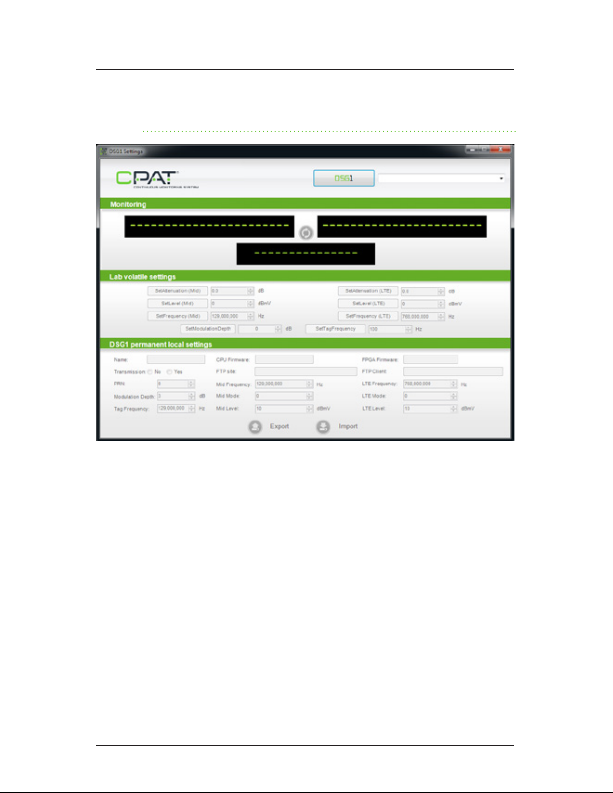
4.3.3 Using the DSG1 settings applications
At startup, the DSG1 settings application displays a “DSG1” button. When you click it, the
application starts looking for all DSG1 units connected on the network.
If several DSG1 units are found, the rst DSG1 found is selected by default. To select a dif-
ferent DSG1, choose another DSG1 from the dropdown menu next to the “DSG1” button.
If no DSG1 units are found, the system displays a special message (“No DSG1 found on the
network”). Make sure that:
• the DSG1 is connected to the network or laptop
• a DHCP server is available
• the IP address family of the DSG1 (displayed on the LCD screen) is reachable by
the computer
• no rewall is blocking UDP port 9051 (used by the DSG1 on rst connection)
CPAT FLEX (DSG1)
14
After the rst successful Export, an “Import” button becomes available in the “DSG1 Perma-
nent local settings”. The Import function applies the DSG1’s editable default settings (startup
frequency, mode and level for each band, transmission activation and startup PRN). These
settings are effective immediately, and they become the new default settings for the next
startup.
NOTE
The DSG1 will always try to connect to the CPAT FTP server. If it succeeds, the
DSG1 will download the active parameters le and overwrite the current one.
To avoid this, do not connect the DSG1 to the Internet until the parameters
have also been set on the CPAT database and stored on the FTP server.
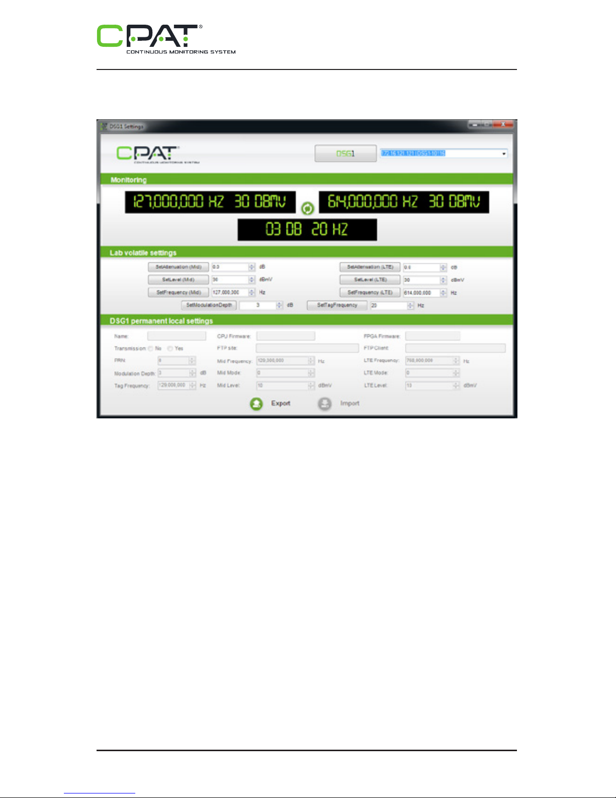
When a DSG1 is selected, the currently applied settings are summarized in the “Monitoring”
panel. All “Lab volatile settings” functions become available for modication, if necessary.
You can edit the attenuation, frequency and level of both bands within the allowed limits.
However, since these settings are volatile, any changes will be lost after a reboot of the
DSG1, and the default settings will be applied until you edit them again.
A “Refresh” button is available between the two outputs in the “Monitoring” panel to perform
a new current settings query.
An “Export” button is available in the “DSG1 Permanent local settings”: when pressed, the
default settings (CPU and FPGA rmware version, FTP URL and user name, startup fre-
quency, mode and level for each band, Transmission activation and startup PRN) are fetched
from the DSG1 and displayed in the “DSG1 Permanent local settings” panel.

efgis.com
15
Operation Manual
After the rst successful Export, an “Import” button becomes available in the “DSG1 Perma-
nent local settings”. The Import function applies the DSG1’s editable default settings (startup
frequency, mode and level for each band, transmission activation and startup PRN). These
settings are effective immediately, and they become the new default settings for the next
startup.
NOTE
The DSG1 will always try to connect to the CPAT FTP server. If it succeeds, the
DSG1 will download the active parameters le and overwrite the current one.
To avoid this, do not connect the DSG1 to the Internet until the parameters
have also been set on the CPAT database and stored on the FTP server.

CPAT FLEX (DSG1)
16
5. System Operation
5.1 Power On
To power on the unit, make sure that the power cable is properly connected to a surge-
protected outlet (recommended) and to the DSG1. Press the ON/OFF button on the front
panel for 3 seconds, and then release it. You should see both lights on the front panel turn
green, and then the PWR light will turn red.
5.2 LED and LCD Information
The two front LEDs indicate the status of the unit.
PWR (power):
• When steadily lit RED, the system is booting (takes about 1 minute to boot).
• When steadily lit GREEN, the system is powered up and booted.
DIAG (diagnostic):
• When OFF, the system is working normally.
• When ashing RED, an error has occurred.
The LCD screen provides information about the unit. It scrolls through the settings to display
the following information:
• Output frequencies for Mid and LTE bands
• Output levels for Mid and LTE bands
• IP address. When there is a problem, several messages can be displayed:
• “NO IP ADDRESS”: No IP address is assigned to the unit. Verify that the network
cable is plug into the Ethernet jack.
• “FTP ERROR”: The DSG1 unit cannot transmit data to the Efgis FTP server. Make
sure that the unit has access to the Internet. Note that the unit can acquire a valid
IP address, but if there is no routing to the Internet, this message will be displayed.
5.3 Communication
The DSG1 exchange les with the CPAT FTP server every 5 minutes. It looks for parameters
le (less than 1 Kb).

efgis.com
17
Operation Manual
5.4 Shutdown
There are two ways to power off the unit: Normal and Force Shutdown. The preferred mode is
Normal shutdown to avoid undesired ash memory corruption. The Force Shutdown function
should be used ONLY if the device is not responding.
5.4.1 Normal Shutdown:
In normal running mode, press the front panel ON/OFF push button for 1 second then let the
DSG1 shut down each process properly. A message will then appear on the front LCD screen,
and the device will turn off.
5.4.2 Force Shutdown:
To force the DSG1 to power down when it is running, press the ON/OFF button on the front
panel for 3 seconds. When the unit has shut down, release the button. Use this shutdown
method only if the normal shutdown method fails.

CPAT FLEX (DSG1)
18
6. System Maintenance
6.1 Cleaning the Equipment
Your DSG1 unit can be wiped clean with a damp cloth. Do not immerse the unit in water.
Avoid solvents and commercial cleaners.
6.2 Preventive Maintenance
The technician shall perform periodic visual inspections on the RF connections to make sure
that there is nothing loose or broken which could affect the performance of the system. If any
replacement parts are required, please contact Efgis for more information.
7. Updates and Recovery
The DSG1 device can be updated manually or automatically, obtaining its rmware when
needed via updates provided from the CPAT FTP server.
7.1 Automatic Update
The DSG1 device is usually automatically updated when needed. The updates are distributed
from the CPAT FTP server to the device. All update are tested to ensure high quality and ef-
ciency in Efgis products. There is no need for external intervention on the device to update
it when using the automatic update function.
7.2 Manual System Recovery
See the Remote Troubleshooting section.
8. Remote Troubleshooting
It is possible to access the DSG1 for remote assistance. Also, manual rmware and script up-
dates can be achieved. If the problem is the Internet connection, it will not possible to do so.
Contact support (see section 1.4 Technical Support)

efgis.com
19
Operation Manual
Appendix A – Specications
A.1 System
Modulator type Dual-band signal
Frequency range output 1 of 2 Agile from 118 to 140 MHz (Mid-band)
Frequency range output 2 of 2 Agile from 572 to 960 MHz (LTE-band)
Frequency stability Mid-band: ±1 kHz
LTE-band: ±5 kHz
Tuning resolution 1 kHz
Modulated signal AM 3 to 110 Hz
Output level from each RF output from +10 to 50 dBmV
Status display Through an LCD on front panel
Communication port 10/100Base-T Ethernet
Setup Through CPAT interface
Power 120 VAC, 0.5A (15W) fully loaded
A.2 Physical
Dimensions Standard 1RU chassis 4.4 cm x 21 cm x 33 cm /
1.75’’ x 8’’ x 13’’ [H x W x D]
Operating temperature -20° to +60° C / -4° to +140° F

CPAT FLEX (DSG1)
20
Appendix B – Our Services
Efgis offers a portfolio of services to deploy and support purchased equipment through its
Customer Support organization. Customer Support is standard with every product sale and
consists of business hour technical assistance, in-warranty repair and calibration.
B.1 System
Customer Support is accompanied with the sale of every Efgis product. Customer Support
services include:
• Product and Service Literature
• Technical Assistance (Business Hours)
• Equipment Repair (Under Warranty Repair and Calibration Services)
• Equipment Return Authorizations
Contact a Customer Support representative through your local distributor or by visiting
www.efgis.com for information on calibration and warranty policies.
B.1.1 Equipment Return Instructions
Please contact your local Customer Support location via telephone for Return Authorization
to accompany your equipment. For each piece of equipment returned for repair, attach a tag
that includes the following information:
• Owner’s name, address, and telephone number
• The serial number, product type, and model
• Warranty status (If you are unsure of the warranty status of your instrument,
contact Efgis’ Customer Support)
• A detailed description of the problem or service requested
• The name and telephone number of the person to contact regarding questions
about the repair
• The return authorization (RA) number
If possible, return the equipment using the original shipping container and material. If the
original container is not available, the unit should be carefully packed so that it will not be
damaged in transit; when needed, appropriate packing materials can be obtained by con-
tacting Efgis Support. Efgis is not liable for any damage that may occur during shipping.
The customer should clearly mark the Efgis’ issued RA or reference number on the outside
of the package and ship it prepaid and insured to Efgis.
Equipment repaired or replaced under warranty will be returned at Efgis’s expense to Cus-
tomer (Canada/USA) or Efgis’ representative (all other countries).
B.2 Limited Product Warranty
B.2.1 Hardware
Efgis warrants to the original end user (Customer) that the new Efgis branded products will
be free from defects in workmanship and materials, under normal use, for one (1) year from
the date of original shipment.
Efgis warrants repaired products for ninety (90) days from date of shipment. Any Product
repaired or replaced under warranty is only warranted for the period of time remaining in the
original warranty for the Product.
Any third party products, including software, included with Efgis products are not covered
by this Efgis warranty and Efgis makes no representations or warranties on behalf of such
third parties. Any warranty on such products is from the supplier or licensor of the product.
B.2.2 Software
Efgis warrants to the Customer that new Efgis branded software and rmware will perform
in substantial conformance to program specications for a period of ninety (90) days from
the date of original shipment. Efgis warrants the media containing software against failure
during the warranty period.
Efgis makes no warranty or representation that the operation of the software products will
be uninterrupted or error free, or that all defects in the software products will be corrected.
B.2.3 Exclusions
This warranty excludes:
• Damage to the physical surface of the product, including cracks or scratches to
any part.
• Damage caused by misuse, neglect, improper installation or testing, unauthorized
attempts to open, repair, or modify the product, or any other cause beyond
the range of the intended use.
• Use of the product with any non-recommended device or service if such device
or service causes the problem.
• Installation or maintenance of Product by someone other than Efgis or persons
certied by Efgis.
• Changes to the Customer environment in which Product was installed.
Table of contents
Popular Inverter manuals by other brands


enphase
enphase Microinverter System Reference manual

Tabor Electronics
Tabor Electronics 5064 user manual

XSY
XSY AT Series manual

SALUPO
SALUPO SOFT START PLUS 1 Instruction and installation manual

TECO-Westinghouse Motor
TECO-Westinghouse Motor EV INVERTER Series operating manual

Toshiba
Toshiba TOSVERT VF-nC3 manual


