TerraTrike Tour II User manual
www.TerraTrike.com - 800.945.9910
4460 40th St SE. Grand Rapids MI, 49512
USA
Assembly Guide
Pilot’s Handbook
Technical Illustration
&
Parts List

Table of Contents
Assembly Guide - Pg 1-15
Pg 1 - Serial Number & Boom Installation
Pg 2 - Rear Wheel Installation & Hubmount (Axle) Installation
Pg 3 - Idler Wheel Installation
Pg 4 - Steering Brace Installation & Tie Rod Installation
Pg 5 - Front Wheel Installation & Handlebar Installation
Pg 6 - Brake Caliper Installation
Pg 7-9 - Alignment
Pg 10 - Align Rear Derailleur Hanger & Rear Derailleur
Installation and Setup
Pg 11 - Front Derailleur Setup & Pedal Installation
Pg 12 - Chain Installation
Pg 13 - Handlebar Cable Housing Routing & Installation
Pg 14 - Seat Clamp Installation
Pg 15 - Seat Installation and Reector Installation
Owners Information - Pg 16-17
Pg 16 - Welcome, Unpackaging, Cautions/Safety, Riding Tips
Pg 17 - Warranty Information
Technical Drawing & Parts List - Pg 18-20
Pg 18 - Tour II Technical Drawing w/Part Numbers
Pg 19 - Tour II Parts List
Pg 20 - Seat Clamp Technical Drawing w/Part Numbers,
Seat Clamp Parts List
Boom Size Chart - Pg 21
Company Information - Pg 22
Assembly Guide
Dark Grey = Installation/Adjustment
PLEASE NOTE: Make sure you’re greasing bolts before installing them. Failure
to do so can cause “galling” to occur (heat and friction will fuse (weld) the fasteners
together). Adjustment will be impossible and not covered under warranty.
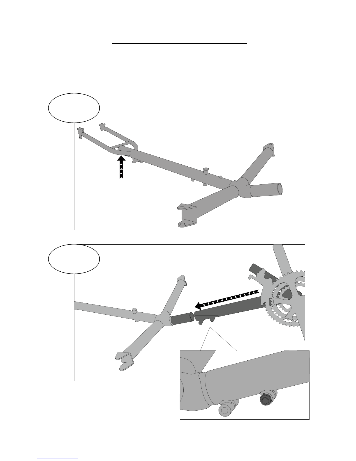
1
Locate/Record Serial Number
2
Boom Installation
Number is located under
the underside of the frame.
1
Boom must be slid all of the way
onto the boom receiver tube so that
none of the non-painted surface is
showing
Torque Spec: 100-125 in lbs
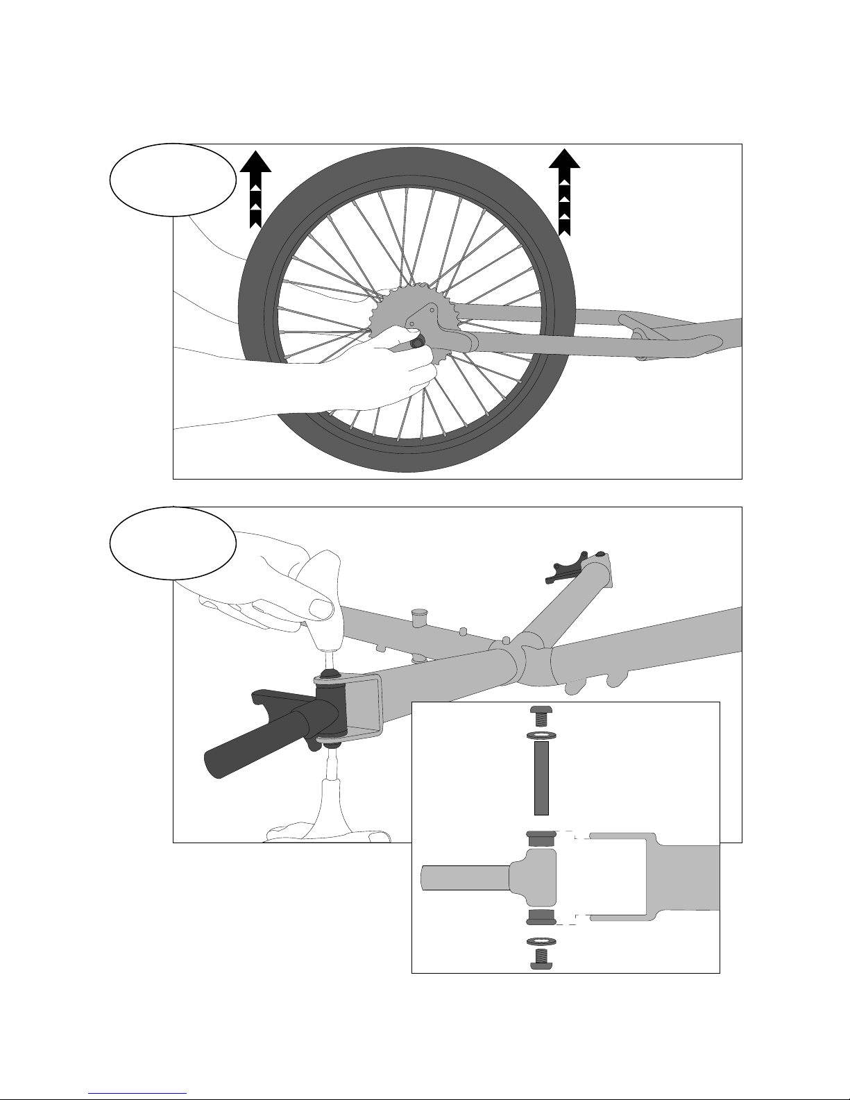
3
4
Rear Wheel Installation
Hubmount Installation
2
Tighten hubmount bolts completely. If
the hubmounts cannot rotate on the
kingpin easily, loosen bolts slightly
until they do. Failure to do so can
result in poor steering performance.
WARNING: please check the kingpins periodically.
Road vibration will cause them to loosen over time!

5
Idler Wheel Installation
M8 Flat
Washer
M8 x90 Bolt
M8 x90 Bolt
Idler Spacer
Idler Spacer
M8 Lock Nut
Idler L Bracket
Idler L Bracket
M8 Lock Nut
Idler Wheel
Idler Wheel
Chain Routing - under both Idlers
Chain Routing - under inside Idler
Chain Routing - over outside Idler
Trike Frame
Trike Frame
PLEASE NOTE: An Additional M8 washer (illustrated in white) may
be required for proper Idler spacing between“L” bracket and Idler.
RIGHT SIDE
OF TRIKE
LEFT SIDE
OF TRIKE
Front Idler Assembly
Rear Idler Assembly
IMPORTANT: Drive portion of chain must be routed on
the idlers closest (inside idlers) to the frame;“return”
portion of chain is routed on the outer idlers.
Idler Spacers
Rear Idler
Assembly
Front Idler
Assembly
3

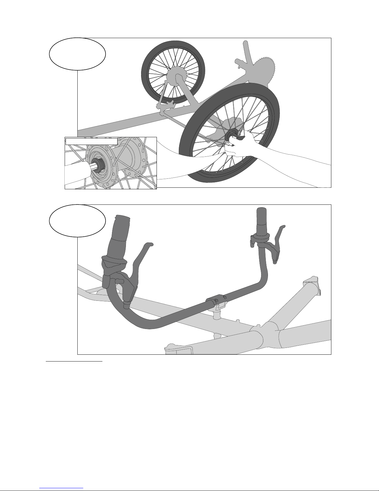
6
Steering Brace Installation
7
Tie Rod Installation
Use M8 washers on the under side of the
steering brace tongue. Install between
steering tongue and tie rod end. THERE
ARE NO WASHERS ON 2011 TOURS
Hubmount
“L” Bracket (computer
sensor mount)
Make sure lines on tie rods are attached as
pictured. This will make alignment easier.
4
8
Front Wheel Installation
9
Handle Bar Installation
Install Axle Bolts
Tighten to 325 in lbs
5
Apply grease to
axle bolts before
installing!
Tighten handlebar
clamp bolts uniformly
Handlebar Adjustment
Your handlebars are adjustable:
1) The Tour II stiffness/ease of steering can be adjusted - you can make your Tour II harder or easier to steer by
adjusting your “steeing brace lock nut.” (number 28 in the technical illustration).
2) Your Tour II handlebars can rotate forward or backward.
If you decide to adjust your Tour II handlebars, follow the below steps:
1) Loosen the 4 clamping bolts that secures your handlebar to the steering brace (number 26 in technical draw-
ing).
2) Rotate handlebars to a comfortable position (you should sit on the trike for this adjustment).
3) Retighten clamp bolts uniformly and securely!
Remember: The handle bars are NOT load bearing elements of the trike and should NOT be used to get in and
out of the trike. Use the seat frame, tops of the tires or derailleur stub tube to enter and exit the trike. THERE IS
A “HOW TO” VIDEO FOR ENTERING AND EXITING THE TRIKE ON THE TERRATRIKE WEBSITE.

Top
Mounted
Caliper
Bottom
Mounted
Caliper
Proper setup: you should see day-
light on either side of the rotor with
bolt screws tightened down. See
below image for bolt location and
fastener layout.
Hubmount M6 washers OR Fender stay
Caliper Bolts
Mounting
Bolts
10
Brake Caliper Installation
6

11
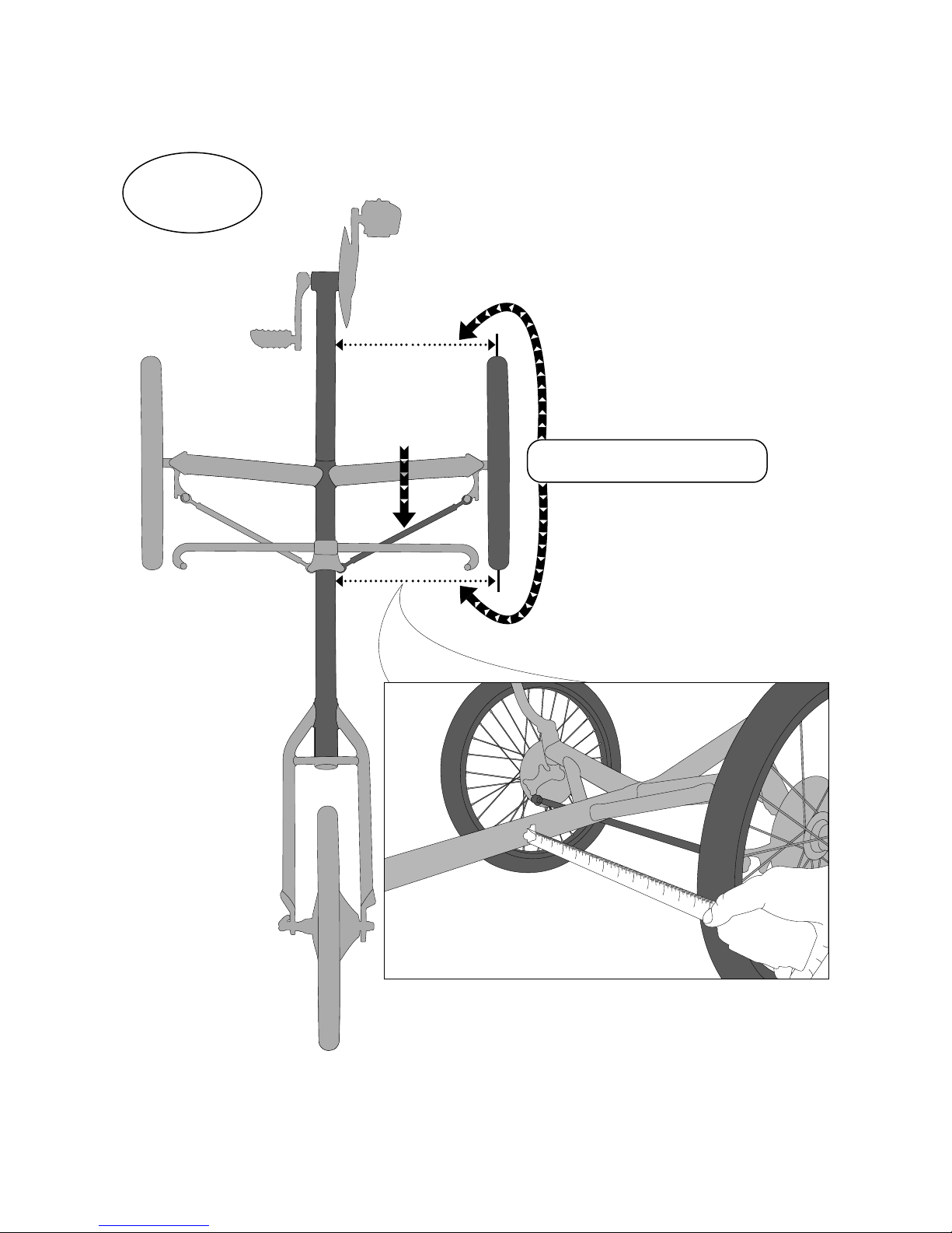
Front Wheel Alignment
Step 1: Make Handlebars Parallel to Outrigger Tubes
Distance = 4 3/4” or 120mm
1. Lock down Steering Brace Lock Nut - This will
prevent the handlebars from moving while
wheel alignment is completed. Loosen nut as
desired when steering setup is complete.
NUT IS ON THE UNDERSIDE OF THE FRAME.
Inate tires to proper PSI before alignment.
7
Tire Pressure
Tire pressure is indicated on the side-wall of of each tire.
TIRE PRESSURE SHOULD BE CHECKED BEFORE EACH RIDE.
11
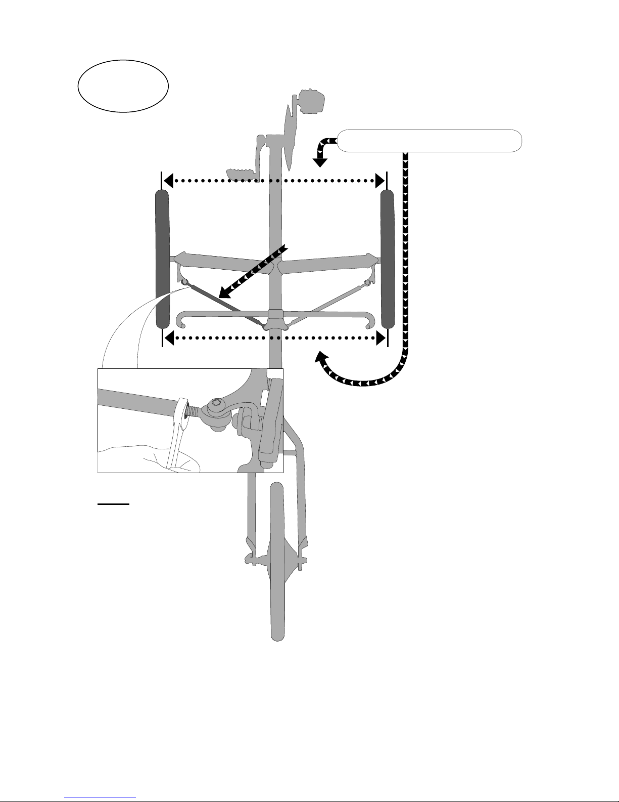
Front Wheel Alignment (Cont.)
Step 2: Make Right Hand Wheel Parallel To Main Tube (Frame)
Rotate tie rod
to move wheel
14 7/8” or 378 mm
8
11
Front Wheel Alignment (cont.)
Step 3: Align Right Wheel To Left Wheel
Distance = 31 5/8” or 803mm
Rotate the opposite tie
rod to align the second
wheel to the rst. Try
not to touch the rst
tie rod already aligned.
BE SURE TO LOCK DOWN
BOTH TIE ROD HEX NUTS
AFTER ALIGNMENT.
Remember to loosen
Steering Brace lock
nut to desired resistance
after alignment is
completed.
IMPORTANT: Try to measure
to the center of each tire. Also,
keep the measuring device
level when measuring.
A millimeter of toe-in on the
front wheel is acceptable. This
may improve high speed
handling.
Double check all measurements before riding. Sometimes the
handle bar can move during the process which alters all other
measurements. An improperly aligned trike will wear tires prema-
turely. This improper setup will not be covered under our war-
ranty. 9

12
Conrm Derailleur Hanger Alignment & Rear Derailleur Installation
Set Rear Derailleur High & Low Stops
13
Grease threads on derailleur before installing!
10
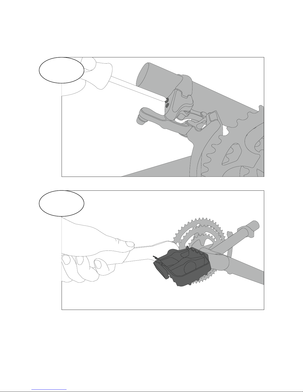
14
Set Front Derailleur High and Low Stops
15
Pedal Installation (tighten securely!)
Grease threads on pedals before installing!
11

16
Chain Installation and Routing
Trike Frame
Front Idler Assembly
Rear Idler Assembly
Trike Frame
Return Chain
Chain
Drive Chain Chain
LEFT SIDE
OF TRIKE
RIGHT SIDE
OF TRIKE
LEFT SIDE
OF TRIKE
RIGHT SIDE
OF TRIKE
Return
Drive
12

17
Shifter and Brake Cable Routing
Left Hand Side of Trike w/Grip Shifter Right Hand Side of Trike w/Grip Shifter
FOR TRIKES WITH GRIP SHIFTERS - Make
sure you route the brake cable behind
the shifter cables (Illustrated above).
LEFT HAND SHIFTER (FOR
FRONT) - Rotate the shifter
so the barrel adjuster faces
backwards.
Don’t forget to crimp cable ends on cables. Cable ends have been provided in your trike kit.
FOR TRIKES WITH BAR END (thumb)
SHIFTERS: The brake cable housing
doesn’t need to be routed behind the
shifter cable housing as shown above.
13

Rear of trike
Front of trike
18 Seat Clamp Installation
Some parts omitted for clarity
14
Seat Mesh and Seat Installation
Upper seat clamp bolt needs to be tight
enough to allow seat frame mounting
tabs to t over sliding seat clamp, use
detent ring pins to secure seat stays
together.
Tighten seat frame bolts before
tightening seat clamp bolts!
19
Install the seat mesh on the
seat frame. After the mesh
is installed on the seat
frame, tuck the excess strap
back up into the buckles.
15
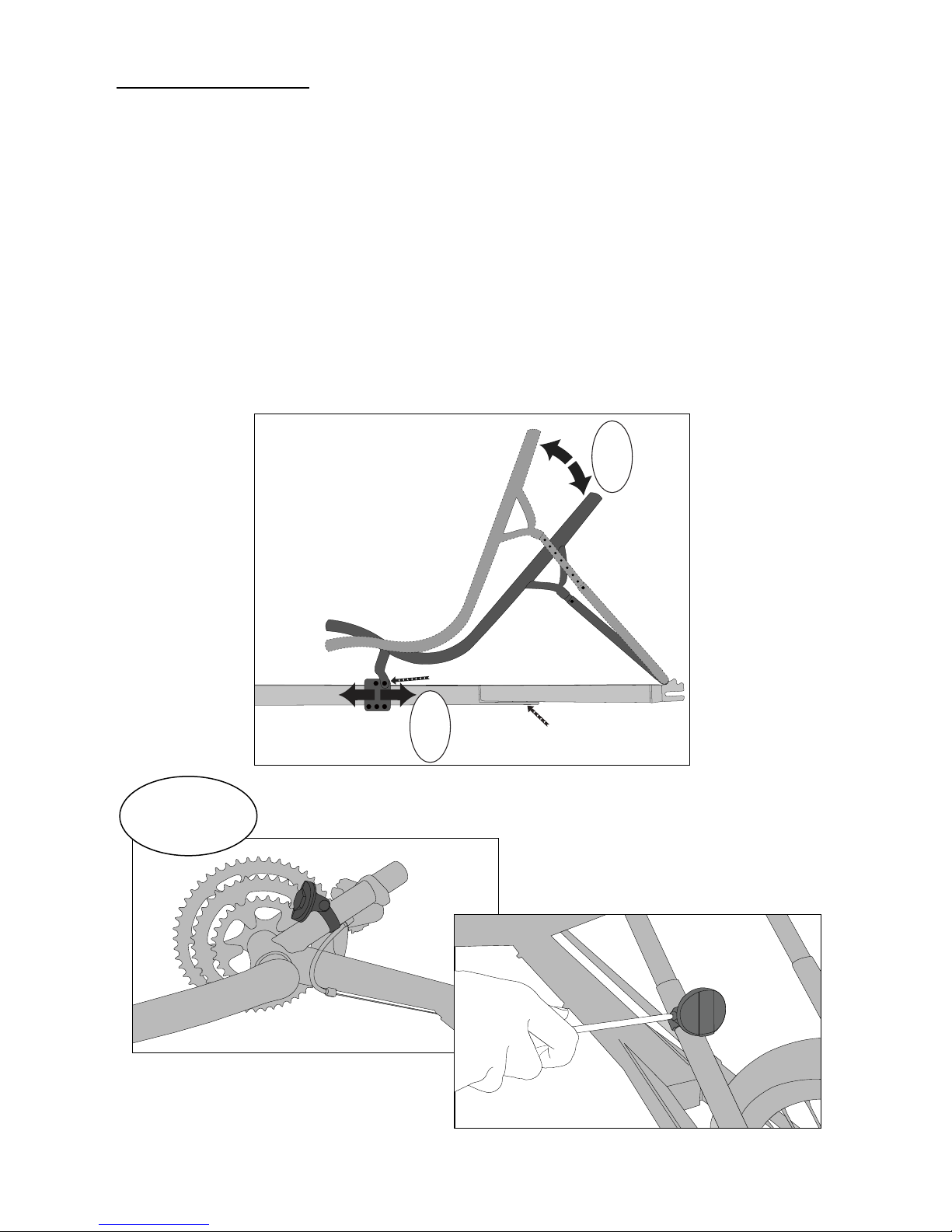
Seating Position Adjustment
Your Tour II’s seat is adjustable on two different planes: fore/aft position at the base and incline/recline
angle of the seat back. Your seating position can adjust anywhere from 40-70 degrees depending on
where the seat clamp is located on the frame.
1) Fore/Aft Seat Position-
To move the base of your seat, loosen the two lower clamping bolts, move the seat, and tighten the
bolts. Your Tour II seat has approximately 6” of total fore/aft movement on the main frame. MAKE
SURE THAT THE SEAT IS CLAMPED SECURELY OR IT WILL ROTATE ON THE MAIN TUBE OF THE
FRAME. THIS CAN LEAD TO LOSS OF CONTROL WHICH CAN RESULT IN SERIOUS INJURY OR
DEATH.
2) Incline/Recline Position-
To adjust the incline/recline position (sitting up-right or laying back), pull the “seat stay pins” (number 3
in technical illustration) from the “seat stays” (number 4 in the technical illustration). You can now adjust
your angle of recline (seat back angle). When you have a seating position you feel comfortable with,
align the holes in the “seat stays” and reinstall your “seat stay pins” MAKE SURE THE HOLES IN THE
SEAT STAYS LINE-UP WHEN YOU REINSTALL YOUR SEAT STAY PINS
Reector Installation
20
Rear Reector on Seat Stay Support
Front reector on front derailleur
stub tube.
Seat Bracket
Rear frame section
1
2

Welcome to our growing Family!
First Things First...Please read the information below BEFORE you go riding. It discusses everything
from unpackaging your trike to trike maintenance to riding tips. We want our customers to be safe and
enjoy their trikes for years to come. Thank you for supporting our company, dealers and families by
choosing TerraTrike.
Unpacking
When your TerraTrike arrives, carefully unpack the contents and inspect for any damage that may have
occurred during shipping. Notify your delivery person of ANY damage on the outside of the box. If
anything is amiss, contact the TerraTrike Sales Ofce immediately at (616) 455-5988. Note: The tires
may have little or no air in them. This is our normal shipping procedure to avoid damage from extreme
altitude uctuations.
It’s a good idea to atten and save all boxes and packing materials. You may need them if you ever
need warranty service or want to ship your TerraTrike.
Cautions/Safety
Stop! Make sure to read and understand this manual completely before riding your TerraTrike. We want
to keep you riding safely for endless miles and years to come. So, always follow these safety precau-
tions for each ride:
•Inspect your TerraTrike before each ride. Check the tires for proper pressure and any damage. Ensure
that the brakes are functioning at their full capacity.
•Please remember a helmet is your most important piece of safety equipment. Wear one!
•If you ride at night make sure you have a white headlight visible from a distance of at least 500 feet, and
a red rear taillight.
•Look behind you! We strongly recommend the use of a rear view mirror. Also make sure to turn your
head and look before turning or changing lanes.
•Use caution when cornering. Learn to use safe speeds for negotiating corners and going down hills.
•Lean into turns when cornering at speed. Your TerraTrike can be “rolled” if turned too sharply for a
given speed. Rule of thumb: rubber side down. :)
•The disc brakes and rotors will get very hot after braking. DO NOT touch them.
•Keep your feet securely on the pedals to prevent them from getting caught underneath your TerraTrike.
We recommend clipless pedals or Power Grip pedal straps.
•Brake evenly using both hands. Your TerraTrike is designed with front brakes only. You will experience
brake-steer if you brake only one side.
•Although your TerraTrike is suitable for riding on dirt roads if equipped with more rugged tires, it is not
designed for all-terrain, off-road use, or canyoneering.
•The unique look of your TerraTrike will attract much attention, so you’re more likely to be seen.
•Be sure you are not obstructed from view by other vehicles. Use of a ag is highly recommended.
•Remember, your rst line of defense is always your own common sense. Ride as if you are invisible to
motorists.
•Your TerraTrike is strong enough for most riding conditions. That is not a license to ride in a hazardous
or abusive manner! Anyone can damage their TerraTrike if they try hard enough. Use common sense.
•Take care of yourself. We like our customers, and we want to keep them around.
Riding Tips
Shifting: Simply twist the shifter up or down to nd the desired gear. Sturmey Archer (internally geared)
hubs should be shifted when you ARE NOT pedalling. External drive trains (derailleur systems) require
pedaling while shifting.
16

•Steering: All of the steering parts tend to settle in after the rst 100 miles or so. This may require some
tightening of nuts and bolts.
•Cleaning: Your TerraTrike will operate for years to come if you keep it regularly cleaned and lubed! Wa-
ter and soap won’t hurt your TerraTrike, provided you dry and lubricate right after cleaning. If you need
to wash the seat mesh, remove it from the seat frame, wash it in the gentle cycle and let it air dry. If you
ride in inclement weather, immediately clean and lube your TerraTrike after your ride. Road salt, over
time, will cause signicant damage to your TerraTrike. Clean it off immediately! Likewise, salty air will
corrode your TerraTrike. It’s a good idea to wax the frame occasionally with a good quality car wax. We
do use stainless steel nuts and bolts.
TerraTrike Lifetime Warranty
Lifetime Warranty
WizWheelz warrants to the original owner that all its trike frames, seat frames, and steering components
are free of defective materials and workmanship subject to the limitations contained in this warranty. This
warranty is limited to the lifetime of the original owner and is nontransferable. The Edge model carries
a 3 year warranty. Warranty is conditioned upon the trike being purchased through and assembled by
WizWheelz or an authorized WizWheelz dealer, operated under normal conditions, and maintained prop-
erly. Warranty does not apply to paint/nish or components attached to the frame. Attached components
are subject to the warranty, if any, of their original manufacturer. Warranty claims must be presented
to the place where the product was purchased whether that is an authorized WizWheelz dealer or the
WizWheelz factory. Proof of purchase must accompany all requests for warranty coverage. WizWheelz
reserves the sole discretion to repair or replace any parts covered by this warranty. Replacement parts
may be a newer version than those originally purchased. Original owner shall be responsible for all labor,
shipping, and travel costs related to repair or replacement of warranted parts. This warranty does not
apply to normal wear and tear, or any defects, malfunctions, or failures that result from abuse, neglect,
improper assembly, improper maintenance, overloading past specied load limit, alterations (i.e. cutting,
spreading, drilling, welding, etc.), collisions, accidents, or misuse.
WizWheelz shall not be liable for any special, indirect consequential, incidental or other similar damages
suffered by the purchaser or any third party, including, without limitation, damages for loss of prots or
business or damages resulting from use or performance of the product, whether in contract or in tort,
even if WizWheelz or it’s authorized representative has been advised of the possibility of such damages
and WizWheelz shall not be liable for any expenses, claims, or suits arising out of or relating to any of
the foregoing.
17
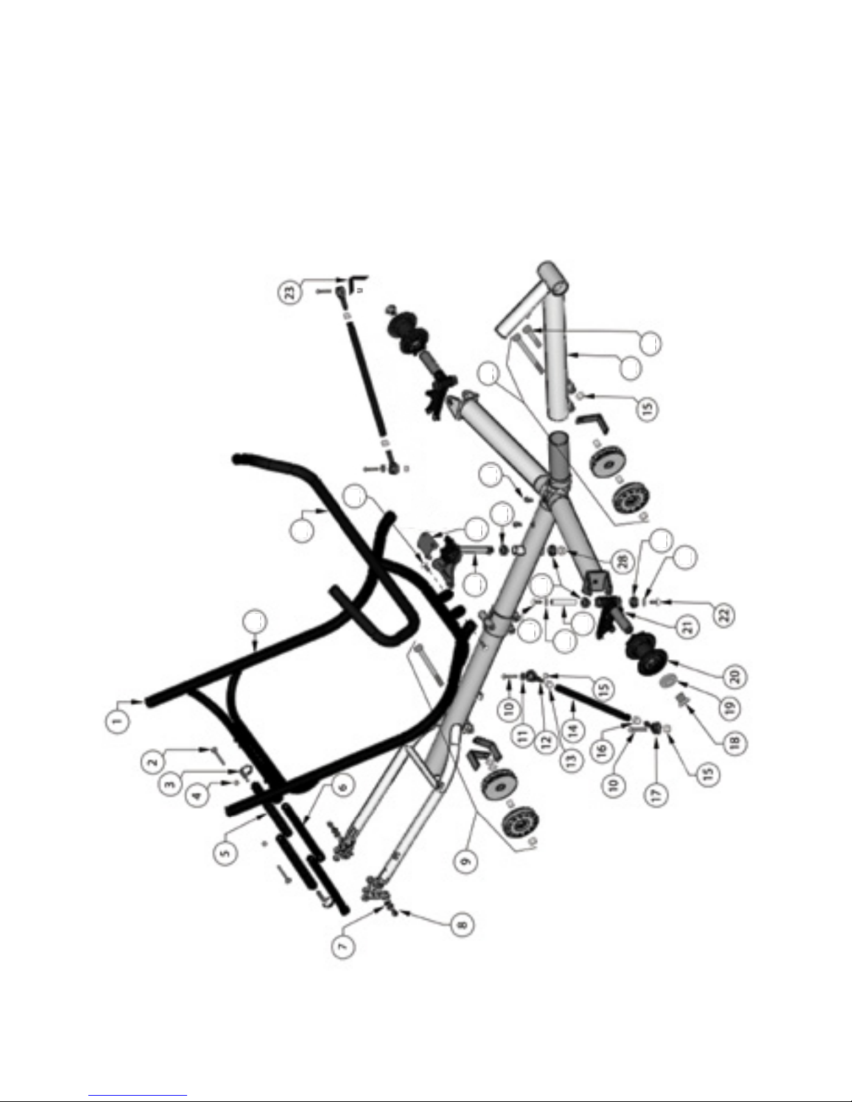
11
11
26
27
27
33
29 30
31
32
24
25
22
22
27
27
Tour II Technical Illustration
&
Parts List
18
Table of contents
Other TerraTrike Bicycle manuals

TerraTrike
TerraTrike SPYDER Manual

TerraTrike
TerraTrike E.V.O. with Bosch Active Line Plus User manual

TerraTrike
TerraTrike Rambler User manual

TerraTrike
TerraTrike Rover User manual

TerraTrike
TerraTrike CHARGE Manual

TerraTrike
TerraTrike GTS Manual

TerraTrike
TerraTrike Sportster User manual

TerraTrike
TerraTrike Rambler 2020 Manual

TerraTrike
TerraTrike Rover Auto NuVinci User manual

TerraTrike
TerraTrike EVO Manual


