Terumo BCT Trima Accel User manual

Trima Accel®
Automated Blood
Collection System
Service Manual

Trima Accel®
Automated Blood Collection System
Service Manual
Part No. 777095-548
2015-09

©2015 Terumo BCT, Inc.
Terumo BCT is aregistered trademark of Terumo Corporation.
VxWorks is a registered trademark of Wind River Systems, Inc.
Terumo BCT, Inc.
10811 W. Collins Avenue
Lakewood, Colorado 80215
USA
USA Phone: +1.877.339.4228
Phone: +1.303.231.4357
USA Fax: +1.866.715.6768
Fax: +1.303.542.5215
Terumo BCT Europe N.V.
Ikaroslaan 41
1930 Zaventem
Belgium
Phone: +32.2.715.05.90
Fax: +32.2.721.07.70
TERUMOBCT.COM

Contents
Preface
1: Operational Description
System Directory ................................................................................................................................................ 1-2
Boot Sequence .................................................................................................................................................. 1-11
Blood Collection Process .................................................................................................................................. 1-12
Pump System ................................................................................................................................................... 1-14
Sensor System ................................................................................................................................................... 1-19
Pressure Sensors ....................................................................................................................................... 1-20
AC Sensor ................................................................................................................................................ 1-21
Reservoir Level Sensors ............................................................................................................................ 1-22
RBC Detector .......................................................................................................................................... 1-23
Leak Detector .......................................................................................................................................... 1-25
Centrifuge System ............................................................................................................................................ 1-27
Filler Assembly ......................................................................................................................................... 1-31
Door System .................................................................................................................................................... 1-32
Valve System .................................................................................................................................................... 1-36
Linear Actuator ................................................................................................................................................ 1-41
E-Box ............................................................................................................................................................... 1-43
Display System ................................................................................................................................................. 1-47
Power System ................................................................................................................................................... 1-51
Mechanical Systems .......................................................................................................................................... 1-52
2: System Description
Pump System ..................................................................................................................................................... 2-2
Pump Assembly ......................................................................................................................................... 2-5
Sensor System ..................................................................................................................................................... 2-7
Pressure Sensors ......................................................................................................................................... 2-8
Reservoir Level Sensors ............................................................................................................................ 2-10
Trima Accel®Automated Blood Collection System • Service Manual i

AC Sensor ................................................................................................................................................ 2-13
RBC Detector .......................................................................................................................................... 2-14
Leak Detector .......................................................................................................................................... 2-15
Centrifuge System ............................................................................................................................................ 2-18
Centrifuge Drive Assembly ...................................................................................................................... 2-22
Centrifuge Motor Controller ................................................................................................................... 2-23
Door System .................................................................................................................................................... 2-26
Valve System .................................................................................................................................................... 2-31
Linear Actuator System .................................................................................................................................... 2-37
E-Box and Computer Systems .......................................................................................................................... 2-40
Control and Safety Functions .................................................................................................................. 2-42
Control CCA ........................................................................................................................................... 2-43
Control Computer ................................................................................................................................... 2-46
Control Ethernet CCA ............................................................................................................................ 2-47
Safety CCA .............................................................................................................................................. 2-48
Safety Computer ...................................................................................................................................... 2-50
Safety Ethernet CCA ............................................................................................................................... 2-51
Motor Driver CCA .................................................................................................................................. 2-52
64 V Switch CCA .................................................................................................................................... 2-54
Cooling Fans .................................................................................................................................................... 2-56
Display System ................................................................................................................................................. 2-58
Display Assembly ..................................................................................................................................... 2-61
Display CCA ........................................................................................................................................... 2-64
Power System ................................................................................................................................................... 2-66
Mechanical System ........................................................................................................................................... 2-70
IV Pole .................................................................................................................................................... 2-70
Wheel and Brake System ......................................................................................................................... 2-71
3: Software Description
Version 5.1 Software Description ....................................................................................................................... 3-2
Trima Accel Software Description ............................................................................................................. 3-2
State and Substate Overview ...................................................................................................................... 3-2
Self Test State ............................................................................................................................................ 3-7
Power Fail Recovery State .......................................................................................................................... 3-9
Startup Tests State ..................................................................................................................................... 3-9
Disposable Tests State .............................................................................................................................. 3-14
AC Connected State ................................................................................................................................ 3-18
AC Prime State ........................................................................................................................................ 3-18
Donor Connected State ........................................................................................................................... 3-19
Blood Prime State .................................................................................................................................... 3-20
Blood Run State ...................................................................................................................................... 3-22
ii Trima Accel®Automated Blood Collection System • Service Manual

Rinseback State ........................................................................................................................................ 3-33
Donor Disconnect State .......................................................................................................................... 3-35
Post Run State ......................................................................................................................................... 3-37
Version 6.0 Software Description ..................................................................................................................... 3-38
Trima Accel Software Description ........................................................................................................... 3-38
Self Test State .......................................................................................................................................... 3-38
Power Fail Recovery State ........................................................................................................................ 3-40
Startup Tests State ................................................................................................................................... 3-40
Disposable Tests State .............................................................................................................................. 3-45
AC Connected State ................................................................................................................................ 3-52
AC Prime State ........................................................................................................................................ 3-53
Donor Connected State ........................................................................................................................... 3-54
Blood Prime State .................................................................................................................................... 3-55
Blood Run State ...................................................................................................................................... 3-57
Rinseback State ........................................................................................................................................ 3-69
Donor Disconnect State .......................................................................................................................... 3-71
Metered Storage Solution State ................................................................................................................ 3-73
Metered Storage Solution Disconnect State ............................................................................................. 3-80
Post Run State ......................................................................................................................................... 3-82
Version 6.1 Software Description ..................................................................................................................... 3-83
Trima Accel Software Description ........................................................................................................... 3-83
Self Test State .......................................................................................................................................... 3-83
Power Fail Recovery State ........................................................................................................................ 3-85
Startup Tests State ................................................................................................................................... 3-85
Disposable Tests State .............................................................................................................................. 3-90
AC Connected State ................................................................................................................................ 3-98
AC Prime State ........................................................................................................................................ 3-98
Donor Connected State ........................................................................................................................... 3-99
Blood Prime State .................................................................................................................................. 3-100
Blood Run State .................................................................................................................................... 3-102
Blood Rinseback State ........................................................................................................................... 3-114
Donor Disconnect State ........................................................................................................................ 3-116
Metered Storage Solution State .............................................................................................................. 3-118
Metered Storage Solution Disconnect State ........................................................................................... 3-126
Post Run State ....................................................................................................................................... 3-127
Trima Accel®Automated Blood Collection System • Service Manual iii

4: Troubleshooting
Touch Screen Troubleshooting .......................................................................................................................... 4-2
Valve System Troubleshooting ........................................................................................................................... 4-4
Version 6.0.6 Dlog Information .............................................................................................................. 4-10
Door System Troubleshooting .......................................................................................................................... 4-17
Version 6.0.6 Dlog Information .............................................................................................................. 4-24
5: Maintenance and Calibration
Aligning the Centrifuge Door ............................................................................................................................. 5-2
Calibrating the Centrifuge Motor Controller ..................................................................................................... 5-5
Positioning the Linear Actuator Sensors ............................................................................................................. 5-8
Removing the Side Panels ................................................................................................................................. 5-11
Saline Run ........................................................................................................................................................ 5-14
6: Specifications
Physical Specifications ........................................................................................................................................ 6-2
Environmental Specifications ............................................................................................................................. 6-3
Electrical Power and Safety ................................................................................................................................. 6-4
Safety Certifications .......................................................................................................................................... 6-11
Performance Specifications ............................................................................................................................... 6-12
Product Specifications ...................................................................................................................................... 6-13
Blood Tubing Sets ............................................................................................................................................ 6-14
Centrifuge ........................................................................................................................................................ 6-15
Safety ............................................................................................................................................................... 6-16
Draw/Return Pressure Sensor ........................................................................................................................... 6-17
Centrifuge Pressure Sensor ............................................................................................................................... 6-18
Reservoir Level Sensors ..................................................................................................................................... 6-19
Fluid Leak Detector .......................................................................................................................................... 6-20
Anticoagulant (AC) Detector ............................................................................................................................ 6-21
RBC Spillover Detector .................................................................................................................................... 6-22
Anticoagulant (AC) Flow Alarm ....................................................................................................................... 6-22
Anticoagulant (AC) Ratio Alarm ...................................................................................................................... 6-23
Anticoagulant (AC) Infusion Alarm .................................................................................................................. 6-24
Touch-Screen Display ...................................................................................................................................... 6-25
Symbols and Certification ................................................................................................................................ 6-26
Seal Safe System Specifications ......................................................................................................................... 6-29
Index
iv Trima Accel®Automated Blood Collection System • Service Manual

Preface
The Trima Accel Automated Blood Collection System Service Manual provides the information needed
to service and troubleshoot the system. This manual applies to versions 5.1.0 and higher. For version 5.0
systems, see the Trima Accel Automated Blood Collection System Service Manual PN 777821-113, RN
704111-003.
Who Should Read This Manual
This manual is intended for Terumo BCT service technicians and employees, trained and qualified
customer technical staff, and Terumo BCT service partners. Only these trained personnel are permitted
to service the device and replace parts.
Trima Accel®Automated Blood Collection System • Service Manual v

How to Use This Manual
This manual is divided into sections that can be read and used separately.
Title Description
Operational
Description
Describes the function and location of certain device systems and components.
System Description Describes the functional and electronic principles of certain device systems and components.
Software Description Describes the software that the device uses to operate.
Alarms Provides alarm text and alarm information.
Troubleshooting Describes non-alarm troubleshooting.
Maintenance and
Calibration
Describes maintenance and service procedures for the device.
Preface
vi Trima Accel®Automated Blood Collection System • Service Manual

1
Operational Description
Trima Accel®Automated Blood Collection System • Service Manual 1-1

System Directory
The Trima Accel system consists of several major subsystems, such as the display, the pump panel, the
centrifuge chamber, and the electronics box (e-box).
The system directory shows the names and locations of some major systems and components in relation
to the whole device. There are figures showing front views and rear views with callout lists to identify
components in each figure. Some figures may not show acallout in the front view, but it will be present
in the rear view. Components that are not called out in the system directory are explained in detail in
their respective Operational Description sections.
Operational Description
1-2 Trima Accel®Automated Blood Collection System • Service Manual

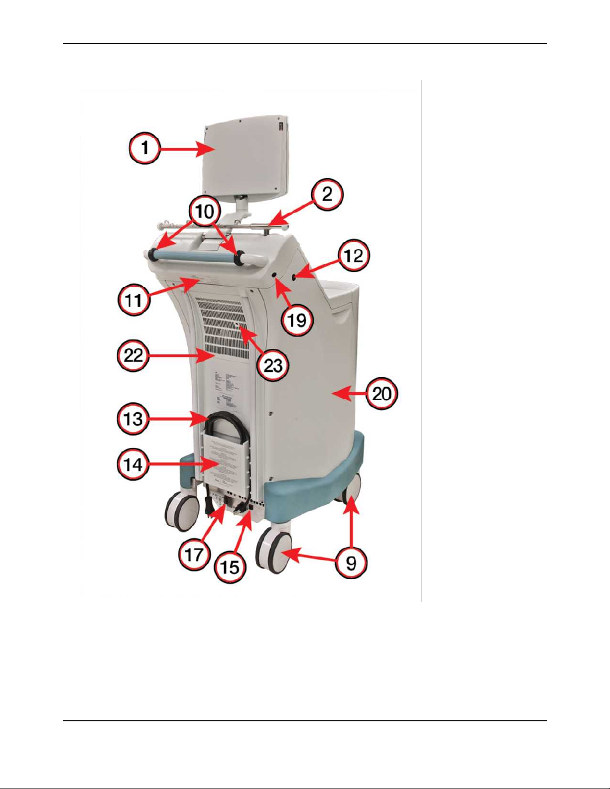
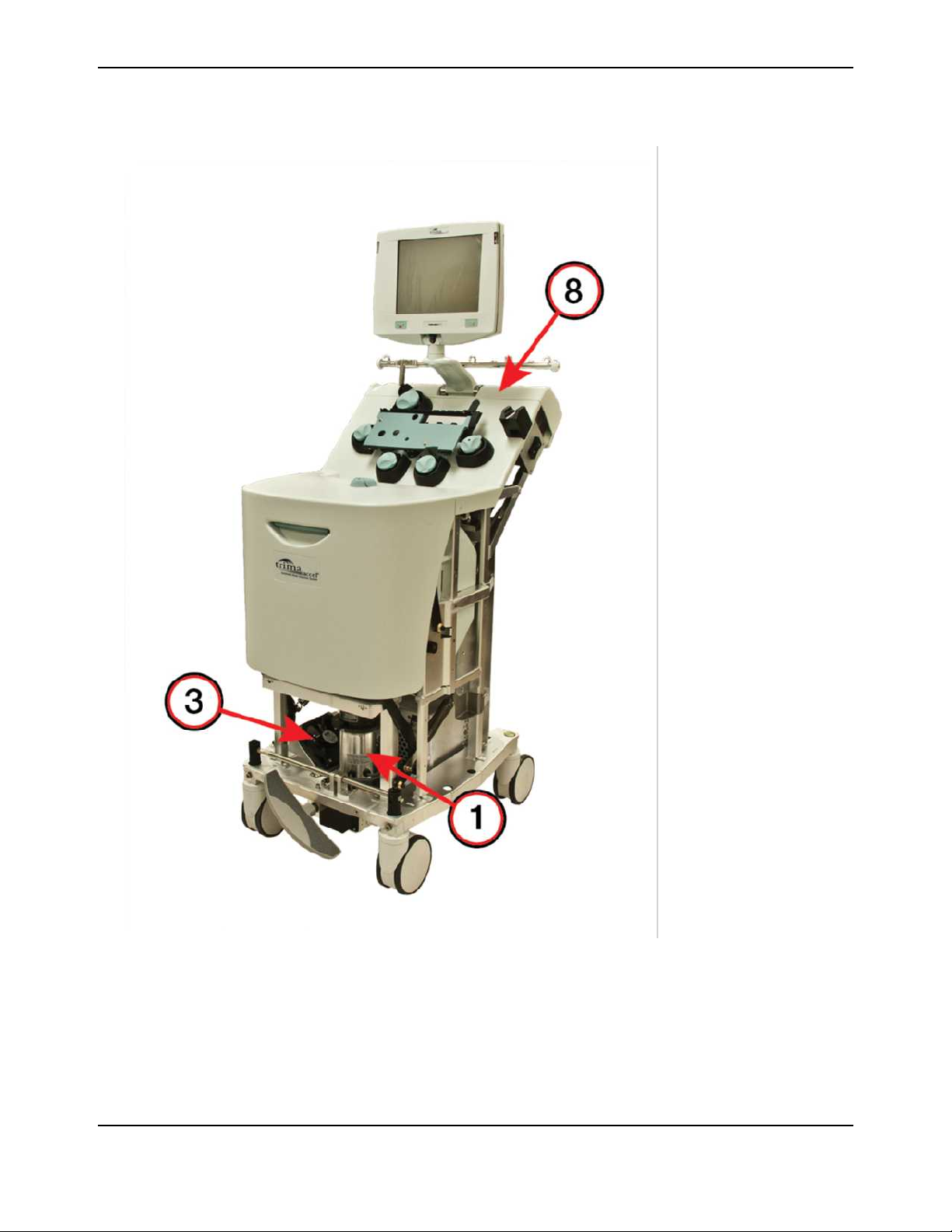
Trima Accel Device Exterior
1Display
2IV pole
3Pump panel
4Seal Safe system
5Cassette plate
6Power switch
7Centrifuge door
8Brake pedal
9Swivel caster
10 Handle wheels
11 System serial number
12 IV pole button
13 Power cord
14 Power cord holder
15 Ethernet connection
16 Door latch handle
17 Circuit breaker
18 Loop damper
19 Handheld barcode
reader outlet
20 Side panel
21 Front panel
22 Rear panel
23 Linear actuator screw
access hole
Figure 1-1: The Trima Accel system, front view
System Directory
Trima Accel®Automated Blood Collection System • Service Manual 1-3
1Display
2IV pole
3Pump panel
4Seal Safe system
5Cassette plate
6Power switch
7Centrifuge door
8Brake pedal
9Swivel caster
10 Handle wheels
11 System serial number
12 IV pole button
13 Power cord
14 Power cord holder
15 Ethernet connection
16 Door latch handle
17 Circuit breaker
18 Loop damper
19 Handheld barcode
reader outlet
20 Side panel
21 Front panel
22 Rear panel
23 Linear actuator screw
access hole
Figure 1-2: The Trima Accel system, rear view
Operational Description
1-4 Trima Accel®Automated Blood Collection System • Service Manual

Table 1-1: Trima Accel system components
Component Function
1 Display Allows you to communicate with the system through audio, visual, or touch-
screen interfaces.
2 IV pole Contains hooks for hanging bags and containers. Adjusts up and down for
transport.
3 Pump panel Holds the pumps, valves, sensors and detectors.
4 Seal Safe system Seals the lines of the tubing set.
5 Cassette plate Holds the tubing set cassette in place.
6 Power switch Allows you to turn power to the system on and off.
7 Centrifuge door Allows access to the centrifuge chamber.
8 Brake pedal Allows you to adjust the direction of the swivel casters for moving the system or to
lock the swivel casters in place so that the system does not roll.
9 Swivel casters (4) Used to transport the system.
10 Handle wheels (2) Facilitates transport of the system in a horizontal position.
11 System serial number Unique number that identifies the system.
12 IV pole button Allows you to lower the IV pole by pressing the button.
13 Power cord Connects the system to a power source.
14 Power cord holder Secures the power cord during transport.
15 Ethernet connection Allows the service computer to communicate with the device.
16 Door latch handle Allows you to open the centrifuge door.
17 Circuit breaker Protects the system from an electrical surge. Secondary power switch used to
power the system on and off.
18 Loop damper Reduces the vibration of the disposable tubing set during a procedure.
19 Handheld barcode reader
outlet
Connects the optional barcode reader assembly.
20 Side panel Covers and protects the internal components from damage, provides containment
in case of catastrophic failure, and is a cosmetic feature.
21 Front panel Covers and protects the internal components from damage, provides containment
in case of catastrophic failure, and is a cosmetic feature.
System Directory
Trima Accel®Automated Blood Collection System • Service Manual 1-5

Table 1-1: Trima Accel system components (continued)
Component Function
22 Rear panel Covers and protects the internal components from damage, holds the power cord,
vents heat from inside the device, and allows access to the screw that is used to
manually raise the cassette plate (used during power failure).
23 Linear actuator screw
access hole
Allows tool access to manually raise the cassette plate to allow the operator to
unload a disposable tubing set if power is lost during a procedure.
Operational Description
1-6 Trima Accel®Automated Blood Collection System • Service Manual
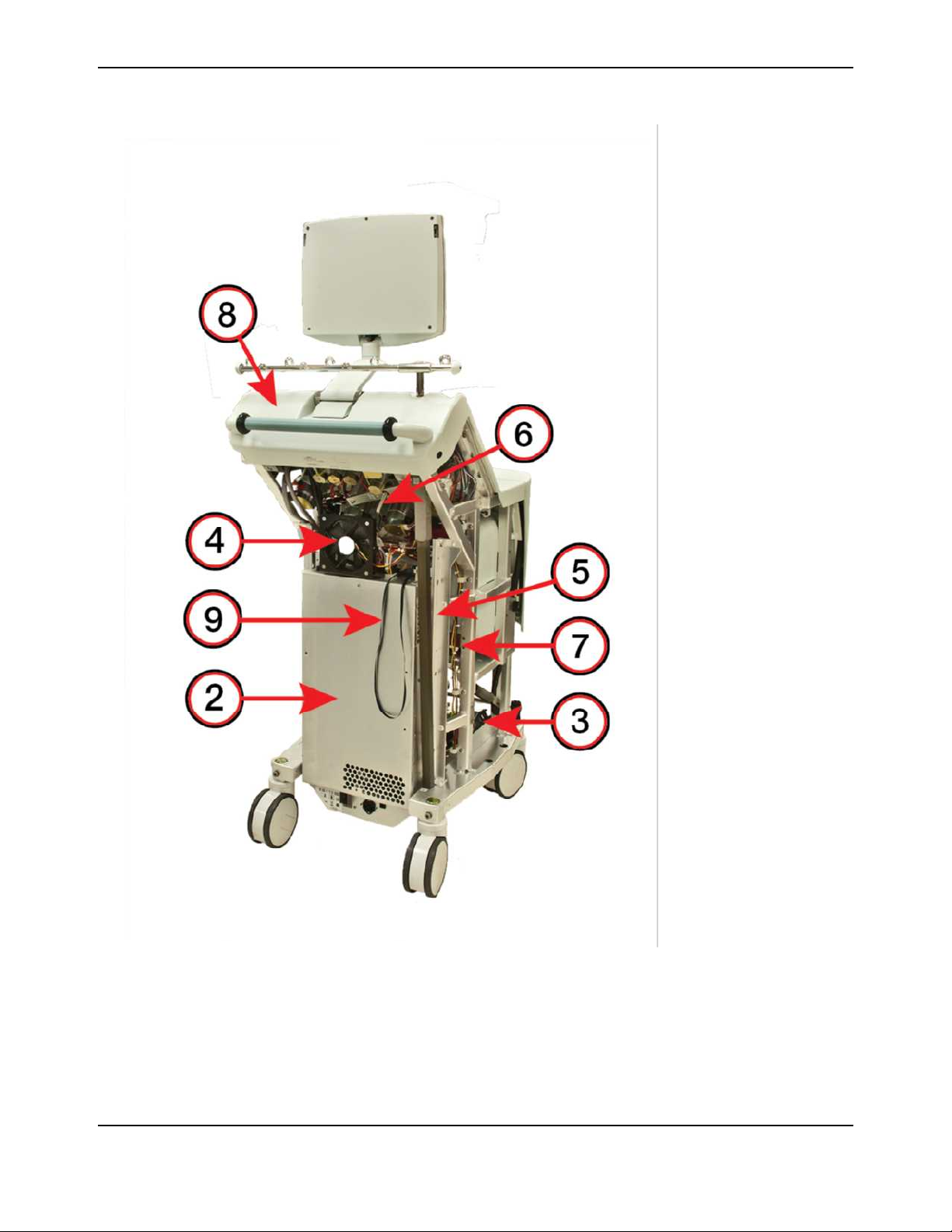
Trima Accel Device Interior
1Centrifuge motor
2E-box
3Lower compartment
cooling fan 1
4Upper compartment
cooling fan 2
5E-box cooling fan 3
(inside e-box)
6Linear actuator screw
7Leak detector CCA
8Top cap assembly
9ESD service strap
Figure 1-3: The Trima Accel system with no panels, front view
System Directory
Trima Accel®Automated Blood Collection System • Service Manual 1-7
1Centrifuge motor
2E-box
3Lower compartment
cooling fan 1
4Upper compartment
cooling fan 2
5E-box cooling fan 3
(inside e-box)
6Linear actuator screw
7Leak detector CCA
8Top cap assembly
9ESD service strap
Figure 1-4: The Trima Accel system with no panels, rear view
Operational Description
1-8 Trima Accel®Automated Blood Collection System • Service Manual

Table 1-2: Trima Accel system components
Component Function
1 Centrifuge motor Spins the disposable tubing set channel that is used to separate blood into its
components.
2 E-box Contains CCAs for the safety and control systems, the hard drive, the motor drive
systems, and the power supply.
3 Lower compartment
cooling (fan 1)
Provides airflow that is used to cool the centrifuge motor and basin.
4 Upper compartment
cooling (fan 2)
Provides airflow that is used to cool the pump and valve motors.
5 E-box cooling (fan 3) Provides airflow that is used to cool the e-box electronics.
6 Linear actuator screw Raises or lowers the cassette plate when the motor is activated.
7 Leak detector CCA Contains the leak detector circuitry.
8 Top cap assembly Contains the display arm assembly, the handle, the Seal Safe connector, and the
barcode reader connector and interfaces with the IV pole. This is a replaceable
component.
9 ESD service strap Provides a secondary ESD (electrostatic discharge) strap if the service
technician does not have a primary ESD strap.
System Directory
Trima Accel®Automated Blood Collection System • Service Manual 1-9
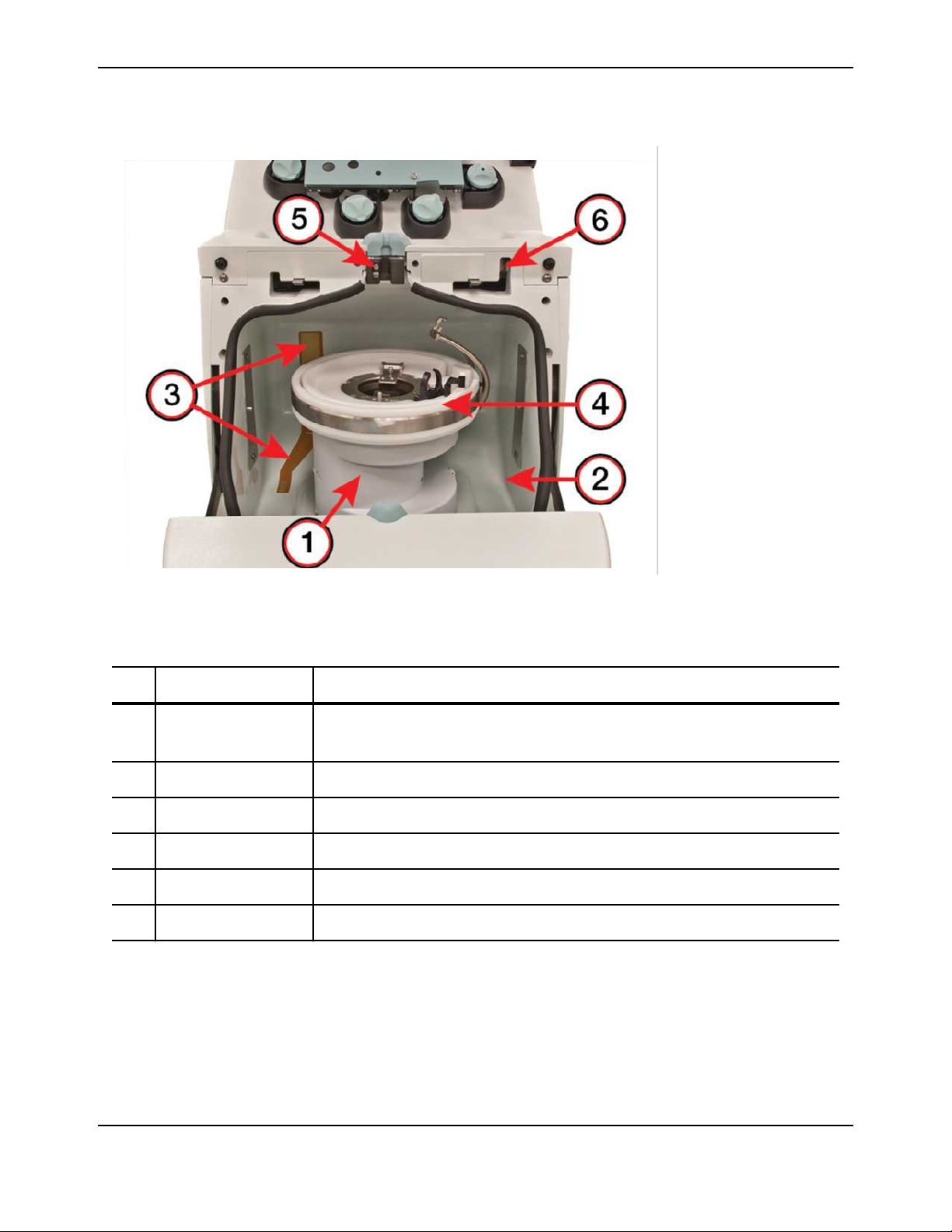
Trima Accel Centrifuge Basin
1Centrifuge
2Basin
3Leak detector
4Filler assembly
5Upper hex holder
6Door lock with sensors
Figure 1-5: The Trima Accel basin
Table 1-3: Trima Accel basin components
Component Function
1 Centrifuge Spins the disposable tubing set channel that is used to separate blood into its
components.
2 Basin Provides protection from catastrophic centrifuge failure and contains fluid leaks.
3 Leak detector Senses fluid in the basin from leaks in the channel or tubing.
4 Filler assembly Holds the disposable tubing set channel where blood component separation occurs.
5 Upper hex holder Holds and locks disposable tubing when the centrifuge door is closed.
6 Door lock with sensors Ensures that the centrifuge door cannot be opened while the centrifuge is spinning.
Operational Description
1-10 Trima Accel®Automated Blood Collection System • Service Manual

Boot Sequence
This section describes the boot sequence and when to interrupt that sequence for troubleshooting and
maintenance purposes.
When it is turned on, the Trima Accel device performs alow-level memory check, generating an alarm if
this check fails. If this check is successful, the device moves on to the boot sequence.
It is possible to interrupt the boot sequence for three different scenarios.
The first scenario is to enter Single-Step mode, which is used to connect the device to STS with an FTP
connection, usually after the safety computer fails to boot and dlogs need to be recovered. To enter
Single-Step mode, press and hold the pause button after the memory check until the screen shows that
the pause button is detected. Then press the pause button to advance through each step of the boot
sequence. Stop at the message line “press and release pause button to initialize serial port driver.”
In FTP mode, STS does not auto-discover the Trima Accel device. To connect, select device type Trima
from the drop-down menu and enter the serial number, or enter the IP address 172.21.127.255 to
connect to a new hard drive. Accept any FTP warnings that appear.
The second scenario is to enable the software load installation script, which is used after new software has
been loaded and needs to be installed. To run the installation script, press and hold the pause and stop
buttons after the memory check, a few seconds after the power is on, and hold the buttons until the
message line “Installation script found—release buttons to execute.” Wait for another message line
reading “Installation complete—cycle power to restart.” Then boot to the two-button donor screen, and
check to make sure the changes took place.
Note: The device allows only one chance to interrupt the normal boot sequence to install new files or software. All
calibration and software data is lost if the device boots to the two-button donor screen after uploading files to the
device. If this installation script is not activated on the first boot, then calibration and software transfer must be
performed again.
The third scenario is to enter Service mode, which is used for software installations, updates, device
maintenance, and device troubleshooting. To enter Service mode, press and hold the pause and stop
buttons after the screen shows the volume checks, and do not release the buttons until the screen
prompts you to do so.
After the boot sequence is finished, the device then checks the power supply voltages, performs valve
position tests, checks the leak detector voltage, and tests the door lock functionality. Without errors to
any of these items the software is then loaded into Procedure mode (two-button donor screen).
Boot Sequence
Trima Accel®Automated Blood Collection System • Service Manual 1-11
Table of contents
Popular Medical Equipment manuals by other brands


PARAMOUNT BED
PARAMOUNT BED A5 Series instruction manual

Stryker
Stryker SDC Ultra manual

Sunrise Medical
Sunrise Medical DeVilbiss RPM AutoAdjust 9054 Series Instruction guide

GlideScope
GlideScope Titanium Operation & maintenance manual

Lloyd
Lloyd GALAXY ULTIMATE Operation manual

Vicks
Vicks V1300EU01 user manual