Terumo ACS-152 User manual
O
SERVICE
..
MANUAL
TUBE
SEALER
ACS-152
TERUMO
CORPORATION
Vo.
|
EN
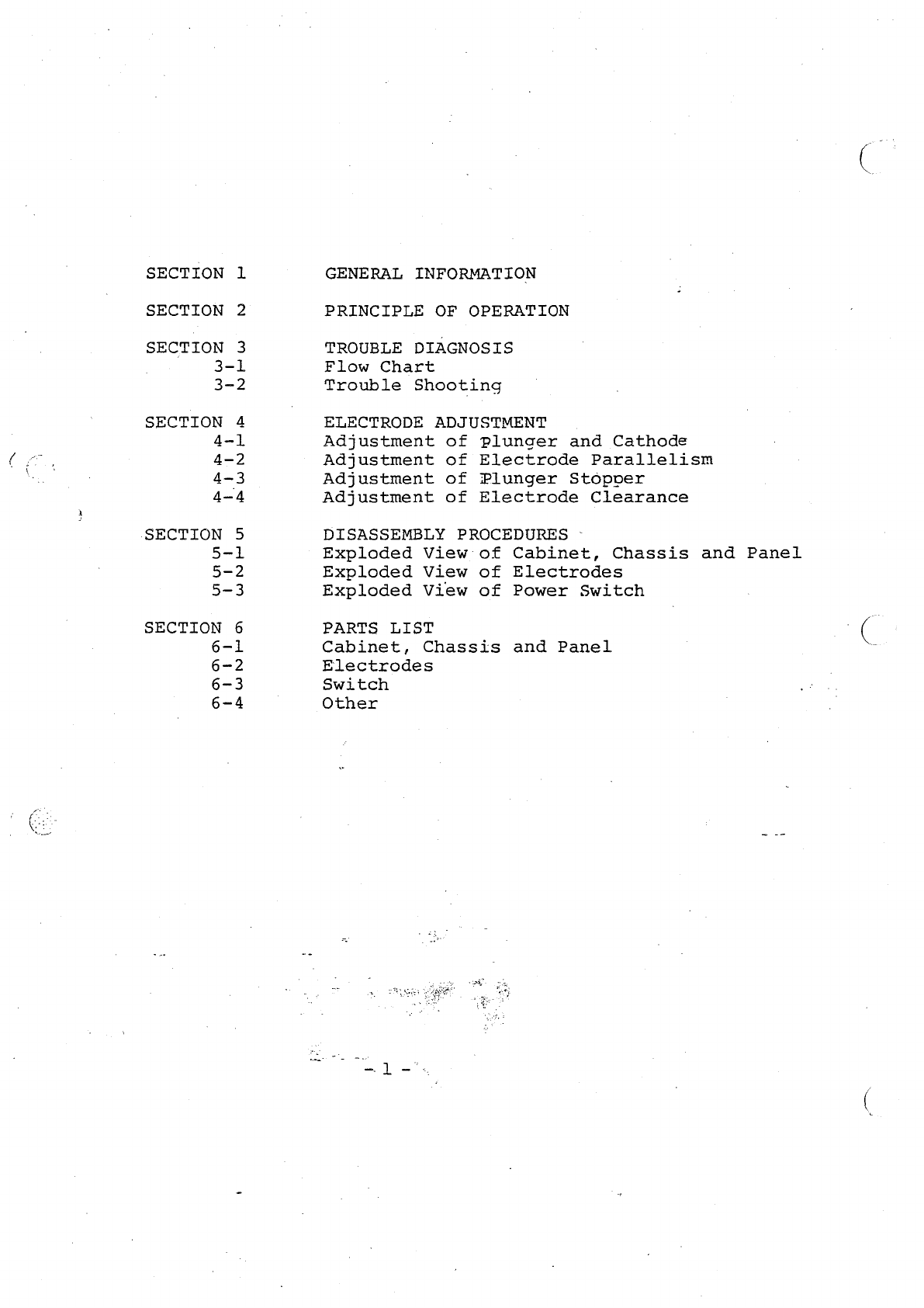
SECTION
1
SECTION
2
SECTION
3
GENERAL
INFORMATION
PRINCIPLE
OF
OPERATION
TROUBLE
DIAGNOSIS
Flow
Chart
Trouble
Shooting
ELECTRODE
ADJUSTMENT
Adjustment
Adjustment
Adjustment
Adjustment
of
Plunger
and
Cathode
of
Electrode
Parallelism
of
Plunger
Stopper
of
Electrode
Clearance
DISASSEMBLY
PROCEDURES
-
Exploded
View
of
Cabinet,
Chassis
and
Panel
Exploded
View
of
Electrodes
Exploded
View
of
Power
Switch
PARTS
LIST
Cabinet,
Chassis
and
Panel
Electrodes
Switch
Other

/
SECTION
1
GENERAL
INFORMATION
This
service
manual
provides
knowledge
required
to
repair
trouble
which
may
occur.
with
ACS-152.
Section
2
covers
the
principle
of
operation.
Read
this
section
before
starting
repairs.
|
Section
3
shows
the
trouble
shooting
flow
chart
and the
diagnosis
table
of
probable
trouble.
Section
4
concerns
the
disassembly
procedures
of
the
major
components
for
reference.
Note:
(1)
Prepare
a
circuit
tester
(2)
High
voltage
power
supply
is
used
in
this
device.
SECTION
2
PRINCIPLE
OF
OPERATION
Normal
operation
Capacitor
C6
is
charged
through
C5
to
operate
RLI
in
the
initial
phase.
When
the
tubing
is
inserted
between
seal
electrodes,
uSl
operates
to
drive
RL1.
At
that
time,
RL2
is
also
operated
by
the
contact
of
RL1,
and
SO(plunger)
pinches
the
tube.
With
RLI
operated,
the
vacuum
tube
operates
to
oscillated
at
40.7
MH
|
The
oscillation
output
dielectrical-ly
heats
the
tubing
to
fuse
it.
When
it
is
fused,
an
electrode
gap
is
shortened.
Then
uS2
operates
to
stop
operation
of
RLl.
When
operation
of
RL1
ends,
.oscillation
stops
and
the
fused
tubing
is
cooled.
Tubing
cool-
ing
time
is
set
by
discharge
of
C7
which
is
connected
to
RL2.
During
this
cooling
time,
SO
(plunger)
which
is
connected
to
RL2
pinches
the
tube.
Operation
under
abnormal
conditions
When
the
tubing
is
wet
by
blood
or
liquids,
high
frequency
short
circuits
between
the
electrodes,
thus
dielectric
heating
of
the
tube
is
not
performed.
If
the
tubing
is
left
under
that
condition,
the
vacuum
tube
can
become
defective.
To
prevent
this,
RL1
operates
only
for
discharge
time
(approx.
4
seconds),
then
oscillation
is
automatically
stopped
,
and
the..plunger
is
returned
to
its
original
position.
ーー
o
Le

Section
3.
Flow
Chart
Turn
Does
Does
Does
TROUBLE
DIAGNOSIS
on
the
power
switch.
|
Yes
|
the
pilot
lamp
come
|
Yes
y
the
plunger
operate
/
the
seal
lamp
light
up
No
>
Table
Table
Table
Table
Table

3-2
Troubleshooting
Table
-
1
:
Pilot
lamp
does
not
come
on..
ne
Power
cable
is
broken
down
Fuse
is
broken
down
Pilot
lamp
is
broken
down.
Check
the
cable
for
continuity
using
circuit
tester.
fa
O
O
O A
a
o
OP
VD
O O
a
аж
инь
UD
ить
O
чить
мии
фито
ши
что
A
NN,
ye
O
O
O
e
O
O o
一
一
ーーーーーーーーーーーーーーーーーーーーーーーーーーーーーーーーーーーーーーーーーーーーーーーーーーーーーーーーーーーーーーー
Replace
3-A
fuse.
Check
for
fuse
open-
ing
cause.
ニニ
ーーーーーーーーーーーーーーーーーーーーーーーーーーーーーーーーーーーーーーーーーーーーーーーーーーーー…ーーーーーーーーーー…
Wiring
to
Check
6.3-V
terminals
of
pri-
Repair
primary
and
mary
and
secondary
windings
of
opening
secondary
power
transformer
for
voltage.
parts.
„of
power
transformer
‘is
broken
down.
Table
-
2
:
Plunger
does
not
operate.
ーー
Cause
Check
Procedure
Remedy
Place
cove
correctly.
Safety
cover
is
detached.
Cause
Check
Precedure
Remedy
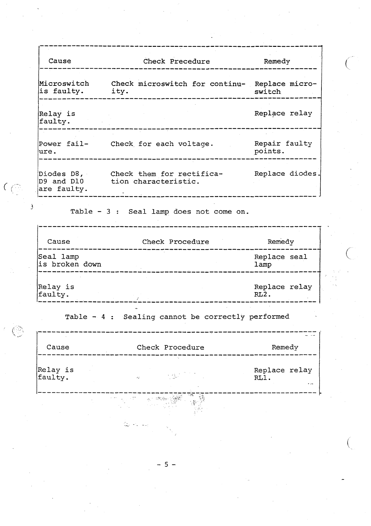
Microswitch
Check
microswitch
for
continu-
Replace
micro-
is
faulty.
ity.
switch
A
σα
σα
σα
σα
σα
mm
ee
ee
eee
4
Relay
is
Replace
relay
faulty.
Power
fail-
Check
for
each
voltage.
Repair faulty
ure.
|
points.
Diodes
D8,
ㆍ
Check
them
for
rectifica-
Replace
diodes.
=
D9
and
D10
tion
characteristic.
(
(
jare
faulty.
3
Table
-
3
:
Seal
lamp does
not
come
on.
Cause
Check
Procedure
Remedy
Seal
lamp
Replace
seal
is
broken
down
|
lamp
Relay
is
Replace
relay
faulty.
.
RL2.
Table
-
4
:
Sealing
cannot
be
correctly
performed
Cause
Check
Procedure
Remedy
Relay
is
m
Replace
relay
faulty.
=
ES
.
RLL.

fo
PT
Cause
Check
Procedure
o
Remedy
Vacuum
tube
is
Replace
vacuum
faulty.
|
Power
is
Check
for
each
voltage
Repair
fauty
points
faulty
Between-
Adjust
the
clearance
|
electrode
clearance
is
improper
Cooling
time
is
RL2
operation
must
end
Renew
C7
deficient
approx.
0.5
sec.
after
RL]
operation
has
ended
SECTION
4
ELECTRODE
ADJUSTMENT
When
electrode
have
been
replaced
and
screws
retightened,
perform
re-adjustment
if
required.
Note
:
When
adjusting
electrode,
always
unplug
the
mit.
Since
there
is
the
potential
of
shock
due
to
electrical.
charge
in
the
capacitor,
discharge
it
before
performing
adjustment.
4-1
Adjustment
of
Plunger
and
Cathode
(1.
Tighten
the
plunger
lock
screw.
Plunger
must
move
smoothly
back
and
forth.
However,
the
plunger
attaching
plate
and
the
solenoid
_
should
be
in
goood
contact.
2.
Firmly
tighten
lock
screws
with
the
cathode
and
anode being
parallel.
Electrode
removable
cover
Cathode
lock
screw
‘Adjusting
0
ノ
Screw
(2)
(
Anode
attaching
/
f
il
|]
Plunger
plate
N
>-
/
-
9
plate
+
. - |
1.
Adjusting,
|
c
一
一
一
screw
(1)|.
Angden
|
bea
NİZ
т
ul
VEE
1
Anode:
Plunger
[lock
"|
MHT.
T
!
screw
F
!
“Wd.
1
o
:
5
5
τ
È
!
tos
HT
;
x
i
-İ
I
一
as
..
・
-
.
O
iz
Mm
に
o
|
+
И
3
!
=>
,
N
Plunger
lock’
screw
VI
-
'
Microswitch
(3)
Adiusting
scfew
i
(3)
electrodo
|
|
.
case
Cl?
Microswitch
(1)
Electrode
case
(2)
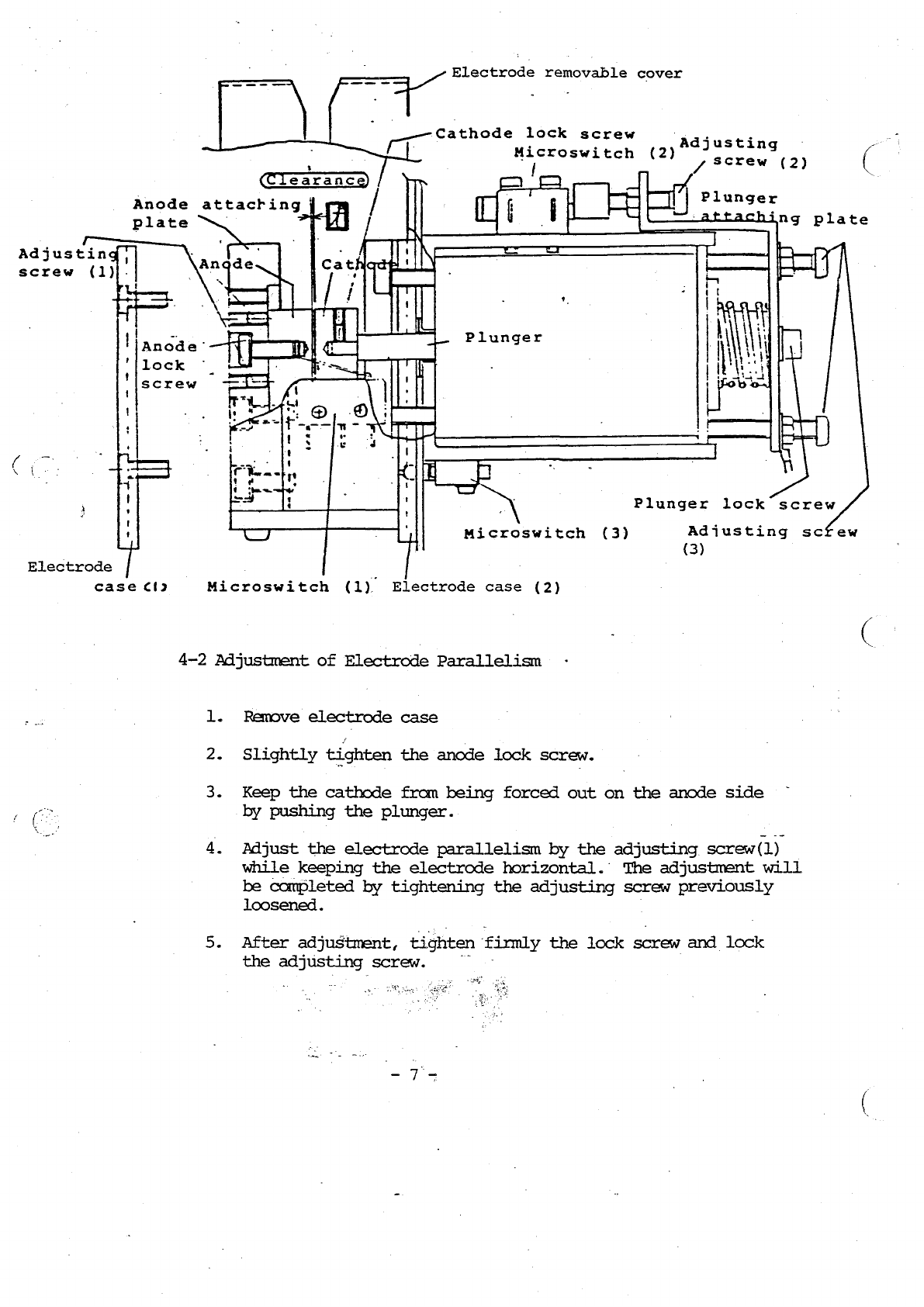
4-2
Adjustment
of
Electrode
Parallelism
Remove
electrode
case
Slightly
tighten
the
anode
lock
screw.
Keep
the
cathode
from
being
forced
out
on
the
anode
side
‚Бу
pushing
the
plunger.
Adjust
the
electrode
parallelism
by
the
adjusting.
screw(1)
while
keeping
the
electrode
horizontal.
The
adjustment
will
be
completed
by
tightening
the
adjusting
screw
previously
loosened.
After
adjustment,
tighten
firmly
the
lock
screw
and
lock
the
adjusting
|
screw.
/
\
.

4-3
Adjustment
of
plunger
stopper
(
1.
Loosen
lock
nut
for
adjusting
screw
(3).
2.
Push
plunger
in
until
adjusting
screw
reaches’
solenoid.
ego
tim
GT
At
that
time,
adjust
clearance
(Tc)
between
electrodes
to
vob
Gem
G7-
0.08
mm
(using
a
thickness
guage)
by
turning
adjusting
screw
(3).
3.
After
adjustment,
set
adjusting
screw
(3)
using
a
philips
screwdriver
and
tighten
lock
nut..
4-4
Adjustment
of
Electrode
Clearance
1.
Loosen
lock
nut
for
adjusting
screw
(2).
z
De
Av)
aj
に
ー
Sem
TT]
すす
ペー
て
パード
2.
Push
plunger
in
until
adjusting
screw
(2)
pushers
microswitch
ンー
and
operation
is
started.
At
that
time,
adjust
electrode
clearance
i.
Sy
TRG
—s
to
0.23'to
9-28
1
mm
(using
a
thickness
gauge)
by
turning
adjusting
|
,
rew
(3).
am
Cricirede
<
Ü
1
o
の
・
15
ee
-
qf
CI
3.
After
adjustment,
set
adjusting
screw.
(2)
using
a
philips
screw-
driver
and
‘tighten
lock
nut.
Tools
used:
Philips
screwdriver
(
hex
socket
wrench
for
M3
wrench
for
7
mm
Thickness
gauge
(0.04
mm
and
0.23
mm)
“ey
=
Sat
Vue-
ее
Dot
Constr
thon
CRE
AIDS
+
TT
©
k
Casromus
δέ
FT
~
foo
Section
5.
DISASSEMBLY
PROCEDURE
g
4
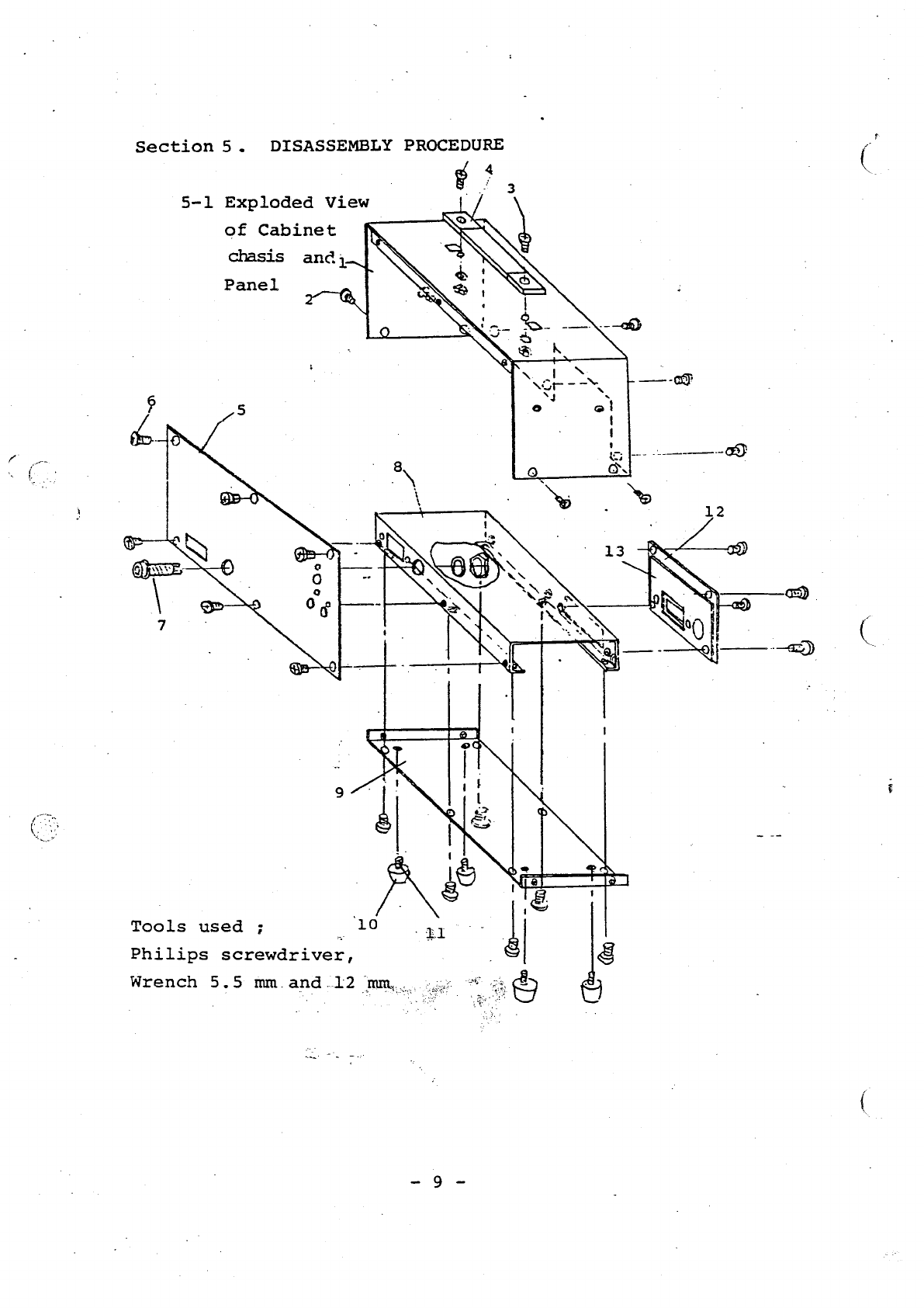
5-1
Exploded
View
7
of
Cabinet
È
chasis
and;
è
©
1
1
à
t
e
‘
‘
Panel
3
Tools
used
;
Philips
screwdriver,
Wrench
5.5
mm.
and.12
mm...

5-2
Exploded
View
of
Electrodes
(
|
Tools
used
;
cu
Philips
screwdriver
(small),
Hex
socket
“39
for
M3
and
Má
40
(bolts),
Wrench
7
mm
and
Pliers
5-3
Exploded
View
of
Power
Switch
Tools
used
;
Philips
screwdriver
and
Wrench
5.5
mm
PT,
-
10
-
и
4
LU
GIONATOS
=
OS
dd
|
)
D
OS
9
HILIMSOYDIN
=
Z
°F
TSN
5
LS
λνΊπα
-
στᾶ
AVIMI
=
TTU
,
my?
5
|
9
IND
|
T
mM
hy
1
ως
и
a
R
や
29
y
A
9
οδοί
ing
AMO
|
。
we20Mz:
AJOS
-
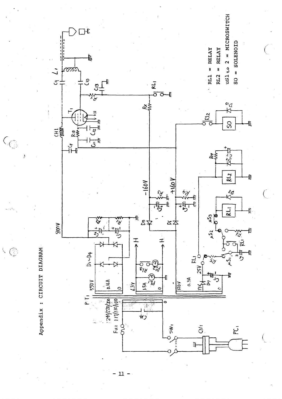
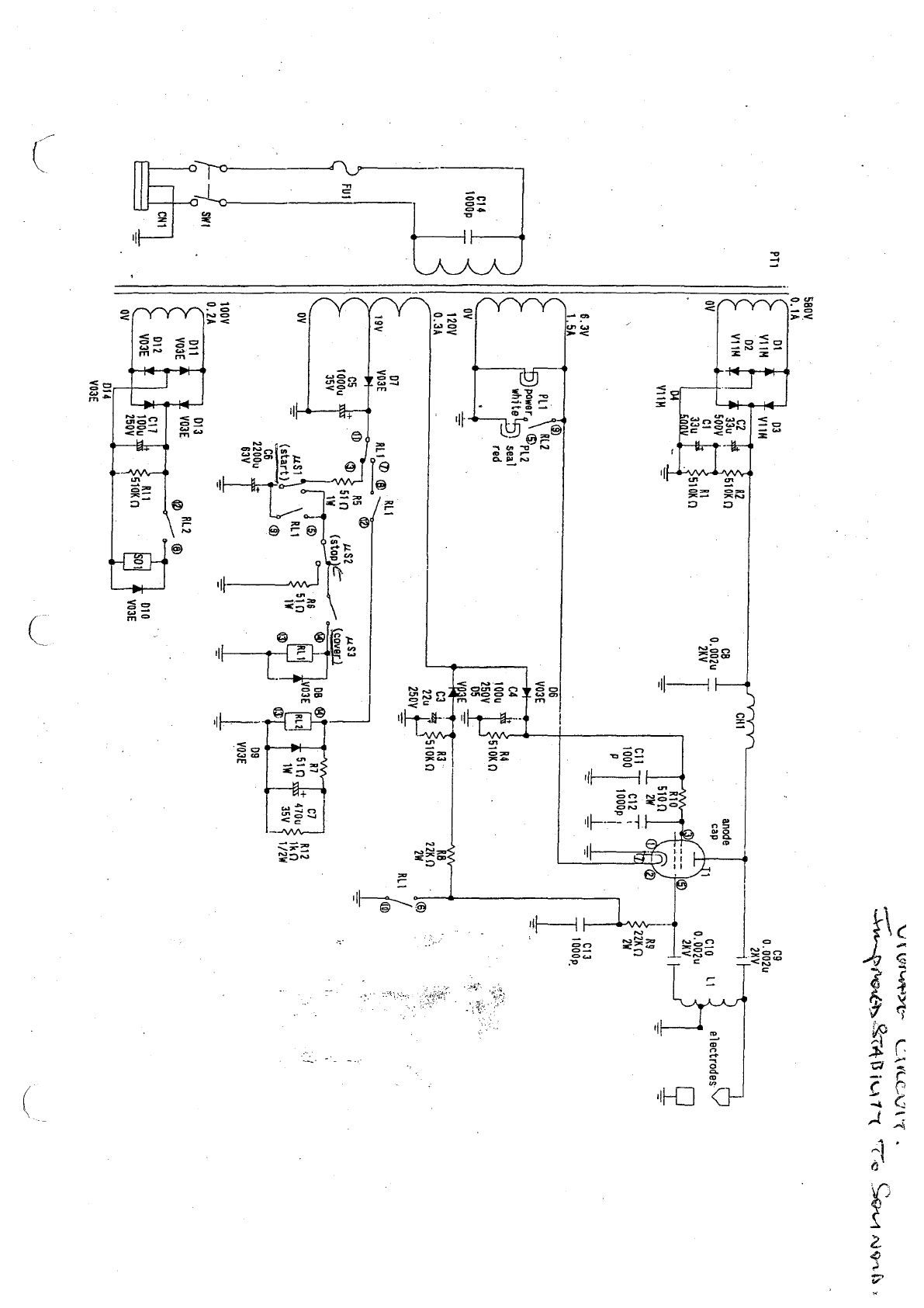
VHDVTO
LINOUID
:
XTpuaddy
WRITE
ACOA
To.
gez”
ss
oe
po
STAB
IUT
Te
580V
0.1A
|
pt
09
PT1
VIM
0.002u
02 eK
。
VI
'
y
ov
+
cio
Li
electrodes:
0.002u
品
6.3V
13
ASA
ο,
e
008
1
-29
Pit
|
REZ
powers
Op
7
white
(SY
sea]
C14
1000p
|
@
@
Ευ!
|
;
a
1
(start)
;
C6
22000
r
63V
1009
L
I
m
0.2A
=
9
`
1
VO3E
1
CN1
m2
1
|
1
W3E
후
010
Яя
VO3E
à
DİZ
—
*
VOIE
LY


ИЯ
ια
Л
므
TIE
.
ο
TLd
3°
ロロ
ロゴ
ロゴ
ロロ
MOTA
UO1104
—


С:
Na
SECTION
6
:
PARTS
LIST
6-1
Cabinet,
Chassis
and
Panel
Ref.
Symbol
Ref.
No.
Description
Model
No.
Q'ty
Remarks
1
Cabinet
2
—
252
1
2
Cabinet
bottom
M3
x
0.5
x
6
17
cover
and
rear
panel
lock
screw
3
Handle
H-16,
3555
1
4
Handle
lock
M4
x
0.7
x
12
2(SW,
,
Screw
N)
5
Panel
_
3
=
65
(out)
1
6
Panel
Lock
screw
M3
x
0.5
x
8
6
PL1
7
Power
lamp
B6
1(SW,
Bulb
H-
N)
5513
8
Chassis
2-253
1
9
Bottom
cover
3-650
1
10
Rubber
cushion
leg
80692
(В)
4
11
Rubber
cushion
leg
M3
x
0.5
x
12
4(W)
lock
screw
|
12
Rear
panel
attach-
4
-
1784
1
ing
plate
13
"Rear
panel
attach-
4 -
1615
1
ing
plate
6-2
Electrodes
Ref.
Symbol
Ref.
No.
Description
Model
No.
Q'ty
Remarks
»
14
Sealer
case.
(1)
4
-
1657
1
15
Case
lock
screw
M4
x
0.7
x
10
2
Plastic
16
Anode
lock
screw
M3
x
0.5
x
10
1(SW)
17
Adjusting
screw
Hexagon
M3
x
2
LD
0.5
x
6
-
18
Anode
lock
screw
4
-
1656
1
19
'
Attaching
plate
Hexagon
M4
x
4(SW)
lock
screw
.7
x
10)
20
Sealer
case
(3)
5
-
2002
1
21
-
Case
lock
screw
M4
x
0.7
x
io
2
plastic
uS1
22
5
-
2000
1
一
|
23
5
-
1999
1
"24.
Hexagon
M3
x
1
ーー
0.5
x
6
25
Solenoid
setbolt
Hexagon
M4
x
2(SW)
ON
0.7
x
10
26
Cable
lock
screw
M3
x
0.5
x
6
1(SW)
27
Coaxial
cable
RG-195
A/U
200mm
Teflon
28
Anode
attaching
4
-
1649
1
.
metal
29
Microswitch
(1)
SSSGL
1
For
start

=.
e
de,
Ref.
Symbol
Ref.
No.
|
Description
Model
No.
Q'ty
Remarks
|
30
Microswitch
lock
M2
x
10
2
(SW)
(
31
Sealer
cover
(2)
4
-
1655
1
32
Sealer
case
plate
4
-
1658
1
33
Stainless
steel
1
Terumo
ball
for
pack
blood
bag
34
Spacer
(S)
1
”35
Plunger
1
36
Solenoid
1
©
4-1659
37
Insulation
tape
Teflon
or
vinyl
ps2
38
Microswitch
(2)
V-1A
|
For
ーー
・
TTT
TTT
clerance
detect-
ion
39
Microswitch
lock
M3
x
0.5
x
15
2(SW)
screw
|
R6
É
40
Solid
resistor
517,
lw
41
Regulation
nose
5
-
2003
42
Plunger
attach-
5
-
1998
ing
plate
43
Adjusting
screw
(2)
M4
x
0.7
x
15
1(N)
44
Adjusting
screw
(3)
M4
x
0.7
x
25
2(SW,
N)
45
Metal
lock
bolt
Hexagon
M4
x
1(SW)
때
46
Ground
wire-
0.7
x
10
200mm
|
(
netting
47
Spring
5
-
2005
1
.
1153
48
Microswitch
(3)
SS5GL-13
1
For
..
e
|
|
safety
49,
Microswitch
lock
M2
x
10.
2(SW)
screw
50°
Insulation
tape
Teflon
or
“vinyl
6-3
Switch
Ref.
Symbol
Ref.
No.
Model
No.
Q'ty
Remarks
52
M3
x
0.5
x
15
2(SW,
a
N)
„53
#6
x
0.4
x
5
54
EST
156
ー
13
-
一
一
一
一 一
一 一
一
一
一
一
一 一
一
一
一
一
一
一
一
一
一
一 一 一
一
一
一
一 一 一
一
一
一
一
一
一
一
一
一
一
一
一
一
一
一 一
一
一
一
一
一
一
一
一
一 一
一
一
一
一 一 一 一
一 一
一
一
一
一
一
一
一 一
一
一
m
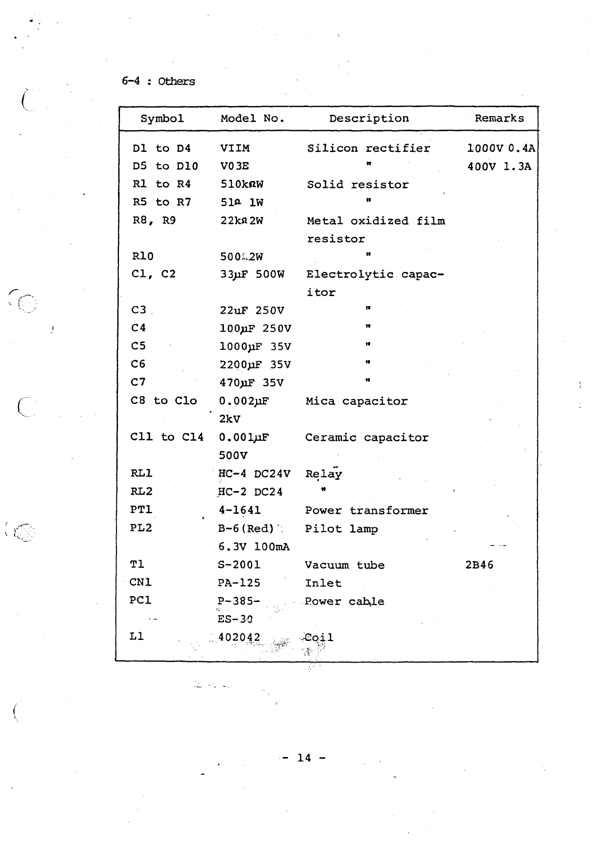
6-4
:
Others
402042-
Symbol
Model
No.
Description
Remarks
01
to
D4
VIIM
Silicon
rectifier
1000
0.4A
DS
to
DIO
VO3E
"
| .
400V
1.3A
RI
to
R4
S10kNW
Solid
resistor
RS
to
R7
512
1W
"
R8,
R9
22k2
2W
Metal
oxidized
film
resistor
R10
500:.2W
|
"
cl,
C2
33uF
500W
Electrolytic
capac-
itor
C3.
22uF
250V
"
C4
100µΕ
250ν
"
C5
1000pF
35V
"
C6
2200µΕ
35ν
"
C7
4701Ε
35V
"
C8
to
Clo
0.002pF
Mica
capacitor
”2kV
611
to
614
0.001pF
Ceramic
capacitor
500V
RLI
(HC-4
DC24V
Relay
RL2
HC-2
DC24
"
|
PTL
_
471641
Power
transformer
PL2
B-6
(Red)
Pilot
lamp
6.3V
100mA
ーー
TI
S-2001
Vacuum
tube
2B46
-CN1
PA-125
Inlet
PCI
P-385-
Oo.
Power
cable
-
ES-39
11
—
14
-

グー
X
Table of contents


