TES TDS-43 User manual

TDS-43 standard version
TDS-43
Touch Monitor
User Manual
Version 01 2018/06

1
About This Document
No part of this publication may be reproduced, transmitted, transcribed, stored in a
retrieval system, or translated into any language or computer language, in any form or
by any means, including, but not limited to, electronic, magnetic, optical, chemical,
manual, or otherwise without prior written permission of TES Touch Embedded
Solutions Inc..
The information in this document is subject to change without notice. TES makes no
representations or warranties with respect to the contents herein, and specifically
disclaims any implied warranties of merchantability or fitness for a particular purpose.
TES reserves the right to revise this publication and to make changes from time to time
in the content hereof without obligation of TES to notify any person of such revisions or
changes. Windows is a registered trademark of Microsoft, Inc. Other brand or product
names are trademarks of their respective holders.

2
Compliance Information
For FCC (USA)
This equipment has been tested and fund to comply with the limits for a Class A digital
device, pursuant to part 15 of the FCC Rules. There limits are designed to provide
reasonable protection against harmful interference when the equipment is operated in a
commercial environment. This equipment generates, uses, and can radiate radio
frequency energy and, if not installed and used in accordance with the instruction manual,
may cause harmful interference to radio communications. Operation of this equipment in a
residential area is likely to cause harmful interference in which case the user will be
required to correct the interference at his own expense.
This device complies with part 15 of the FCC Rules. Operation is subject to the following
two conditions: (1) This device may not cause harmful interference, and (2) this device
must accept any interference received, including interference that may cause undesired
operation.
For IC (Canada)
CAN ICES-3(A)/NMB-3(A)
For CE (EU)
The device complies with the EMC Directive 2014/30/EU and Low Voltage Directive
2014/35/EU
Warning:
This is a class A product. In a domestic environment this product may cause radio
interference in which case the user may be required to take adequate measures.

3
Usage Notice
Precautions
Please follow all warnings, precautions and maintenance as recommended in this user’s
manual to maximize the life of your unit.
Do
:
Turn off the product before cleaning.
Use a soft cloth moistened with mild detergent to clean the product housing.
Use only the qualified power adapter that comes with your device.
Disconnect the power plug from AC outlet if the product is not going to be used for an
extended period of time.
Don’t
:
Do not use abrasive cleaners, waxes or solvents for your cleaning.
Do not operate the product under the following conditions:
- Extremely hot, cold or humid environment.
- Areas susceptible to excessive dust and dirt.
- Near any appliance generating a strong magnetic field.
! Warning - To prevent the risk of fire or shock hazards, and do not
expose the product to moisture.
! Warning - Please do not open or disassemble the product as this may
cause electric shock.

4
TableofContents
Chapter 1........................................................................................................................5
1.1 Overview....................................................................................................................6
1.2 Feature ......................................................................................................................6
1.3 Specifications.............................................................................................................6
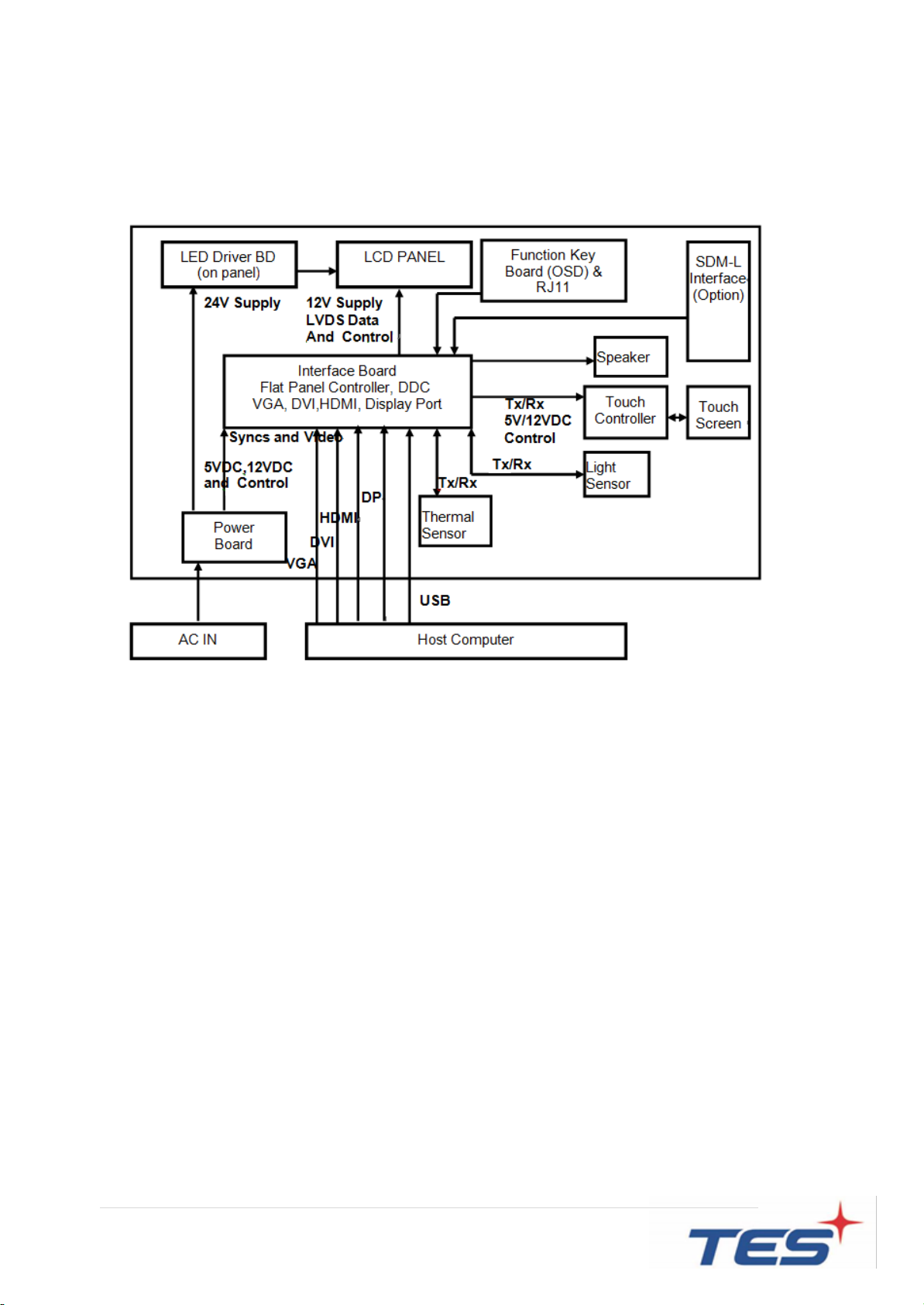
1.4 Block Diagram............................................................................................................7
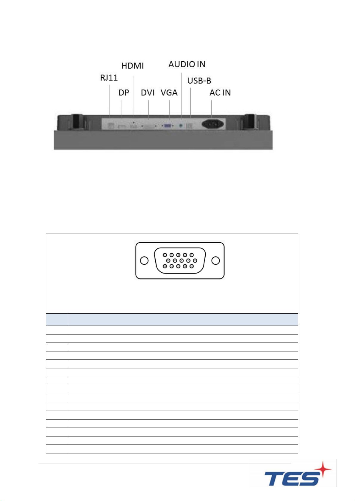
1.5 Interface Connectors..................................................................................................8
1.5.1 Power Connector ...............................................................................................8
1.5.2 Video Signal Connector .....................................................................................8
1.5.3 Signal Connector..............................................................................................10
1.6 Package Overview...................................................................................................12
Chapter 2......................................................................................................................13
2.1 About VESA Mount..................................................................................................14
2.1.1 Install the VESA screw.....................................................................................15
2.2 About General Mounting Information.......................................................................16
2.2.1 Landscape .......................................................................................................16
2.2.2 Portrait .............................................................................................................16
2.3 On-Screen Display...................................................................................................17
2.3.1 OSD Function Description................................................................................19
2.3.2 Timing Table Chart...........................................................................................20
2.3.3 EDID Data........................................................................................................20
2.4 Dimension................................................................................................................21
2.4.1 Front View........................................................................................................21
2.4.2 Side View.........................................................................................................21
2.4.3 Rear View ........................................................................................................22
Appendix........................................................................................................................23

5
Chapter 1
Product Introduction

6
1.1 Overview
TDS-43 series not only supports portrait and landscape two ways suitable for all solutions,
but also provides dynamic touch sensitivity technology supports up to 6mm thickness
glass. TDS-43 series is designed for retail, KIOSK, digital signage etc.
1.2 Feature
Flat Type Design: create better interactive experience for user
43” with 20mm with 18mm ultra-slim border
IP65/Palm Rejection
Anti-Glare Surface treatment
Passed 60950-1 criteria Ball drop testing
10pts Touch Support
Supporting 24/7 non-stop operate service
1.3 Specifications
LCD Touch Panel
Size
43” TFT LCD
Brightness
450 cd/m2(Non-touch screen)
356 cd/m2 (P-CAP)
Number of Pixels
1920(H) x 1080(V)
Touch Type
P-CAP/ 10 points
Environment
Power Input
100-240V ~ 2A 50/60Hz
Operating Temperature
0C ~ 40C
Storage Temperature
-20C ~ 60C
Operating Humidity
20% ~ 80% RH, non-condensing
Mounting
VESA 400 mm x 400 mm
Dimension (W x H x D)
571.42mm x 80.7mm x 983.18mm
Net Weight
19.5 kg
Gross Weight
25.0 kg

7
1.4 Block Diagram
This section describes the electrical requirements of the monitor. The block diagram
in figure 1 illustrates the various electrical sub-systems.

8
1.5 Interface Connectors
1.5.1 Power Connector
The AC converter shall have an IEC320 type male power receptacle for connection
to AC mains power. The power cord, exact type to be supplied in the appropriate
Option Kit, shall be length of 1.80.05 meters, and PC99 compliant.
1.5.2 Video Signal Connector
VGA
The video signal input via D-type 15-pin female connector.
Connector Pin Assignment:
Pin
Signal
1
Red video signal input
2
Green video signal input
3
Blue video signal input
4
NC
5
DDC ground for the VESA DDC2B function
6
Analog signal ground for the red video
7
Analog signal ground for the Green video
8
Analog signal ground for the blue video
9
+ 5V: Input from host system for the VESA DDC2B function
10
Signal ground
11
NC
12
SDA signal input for the VESA DDC2B function
13
Horizontal signal input from host system
14
Vertical signal input from host system
15
SCL signal input for the VESA DDC2B function

9
HDMI(1.4)
The video signal input via HDMI female connector.
Connector Pin Assignment:
Pin
Signal
Pin
Signal
1
TMDS Data2+
11
TMDS Clock Shield
2
TMDS Data2 Shield
12
TMDS Clock–
3
TMDS Data2–
13
CEC
4
TMDS Data1+
14
Reserved (N.C. on device)
5
TMDS Data1 Shield
15
SCL
6
TMDS Data1–
16
SDA
7
TMDS Data0+
17
DDC/CEC Ground
8
TMDS Data0 Shield
18
+5V Power
9
TMDS Data0–
19
Hot Plug Detect
10
TMDS Clock+
DVI
The video signal input via DVI female connector.
Connector Pin Assignment:
Pin
Signal
Pin
Signal
1
TMDS Data 2-
13
TMDS 3+
2
TMDS Data 2+
14
+5V DDC Power
3
TMDS Data 2/4 Shield
15
Gnd (+5, Analog V/H Sync)
4
TMDS 4
16
Hot Plug Detect
5
TMDS 4
17
TMDS Data 0-
6
DDC Clock
18
TMDS Data 0+
7
DDC Data
19
TMDS Data 0/5 Shield
8
No Connection
20
TMDS Data 5-
9
TMDS Data 1-
21
TMDS Data 5+
10
TMDS Data 1+
22
TMDS Clock Shield
11
TMDS Data 1/3 Shield
23
TMDS Clock+
12
TMDS 3-
24
TMDS Clock-C1

10
1.5.3 Signal Connector
USB Connector
Pin
Signal
1
VCC
2
D-
3
D+
4
GND
Display Port(1.2a)
Pin
Signal
Pin
Signal
1
ML_Lane 3(n) Data3 -
11
Signal ground
2
Signal ground
12
ML_Lane 0(p) Data0 +
3
ML_Lane 3(p) Data3 +
13
Signal ground
4
ML_Lane 2(n) Data2 -
14
Signal ground
5
Signal ground
15
AUX_CH(p) AUX + Signal for
Auxiliary Channel
6
ML_Lane 2(p) Data2 +
16
Signal ground
7
ML_Lane 1(n) Data1 -
17
AUX_CH(n) AUX - Signal for
Auxiliary Channel
8
Signal ground
18
Hot Plug
9
ML_Lane 1(p) Data1 +
19
DP_PWR Return
10
ML_Lane 0(n) Data0 -
20
DP_PWR

11
RJ11 Connector (Remote Key)
Pin
Signal
1
MENU
2
UP
3
DOWN
4
SELECT
5
POWER
6
GND
Line-in Connector
Pin
Signal
1
GND
2
LEFT
3
RIGHT
4
LEFT
5
RIGHT

12
1.6 Package Overview
LCD Display
Power Cord
DP Cable
USB Cable (A to B)
Audio Cable
VGA cable
Quick Start Guide
M4 screws x 12 pcs
This product is intended to be supplied by a AC-in Power source, rated
100V~240V, 2.0A 50/60Hz minimum, Tma = 40 degree C minimum, and the
altitude of operation = 3048m minimum. If it needs further assistance with
purchasing the power source, please contact to TES for further information.
! Warning!
This product is intended to be supplied by a AC-in Power source, rated
100V~240V, 2.0A 50/60Hz minimum, Tma = 40 degree C minimum, and the
altitude of operation = 3048m minimum. If it needs further assistance with
purchasing the power source, please contact to TES for further information.

13
Chapter 2
Product Installation

14
2.1 About VESA Mount
The TDS-43 series conform to the “VESA Flat Display Mounting Interface Standard”
which defines a physical mounting interface for touch monitor and corresponding
with the standards of touch monitor mounting devices. The VESA mount is located
on the back of this unit.
! Warning!
Please select the TES original screws!
The distance between the back cover surface and the bottom of the screw hole
is 6~7 mm. Please use M5 screws diameter with proper length to mount your
monitor.
Note: The mounting stand must be able to support at least 33 lbs (15.0 Kg).

15
2.1.1 Install the VESA screw
Note: Please install/ dismantle the product when the device is in the shutdown state.
Step 1: Fasten two M6 screws into the VESA hole
Step 2: Fasten four M6 screws into the VESA hole

16
2.2 About General Mounting Information
The following two mounting orientations are supported: Landscape and portrait
mode. For optimal touch performance, ensure that the monitor is supported fully and
is as flat as possible.
2.2.1 Landscape
2.2.2 Portrait

17
2.3 On-Screen Display
The TDS-43 series provide side panel controls. And the following is OSD function
table:
OSD
Key
Menu off status
Menu on status
MENU
Menu appear
Menu disappear/ return to main
item
▲
Brightness
Main item select up/ Adjust up
▼
Contrast
Main item select down/ Adjust
down
SELECT
Auto Adjusting
Enter/Select sub-item function
Power On/Off
1. Press the “MENU” button to pop up the “on-screen menu” and press “Up” or
“Down” button to select among the five functions in the main menu.
2. Press “SELECT” to enter the sub menu, and then use “Up” or “Down” button to
select the adjustable functions.
3. Choose the adjustment items in the sub menu by pressing the “SELECT”
button.
4. Adjust the value of the adjustment items by pressing the “Up” or “Down” button.
5. With the OSD menu on screen, press “Menu” button to return main menu or exit
OSD.
6. The OSD menu will automatically close, if you have left it idle for a pre-set time.

18
7. To Lock the OSD / Power menu buttons, please follow the instructions below.
(Please note: the monitor has to be turned ON with a valid signal pre-set)
a. Without the OSD menu on screen, press and hold “Menu” key ,and press
“POWER” once then release “MENU” key. The “Lock/Unlock” menu will
appear for 5 seconds.
b. Use the "UP” and “DOWN key to select OSD or Power setting then set at
“Lock” (or “Unlock” ) by pushing the "ENTER" button.
c. When pressing “MENU” button , the previous setting will be saved and exit
the “Lock/Unlock” menu automatically.
Please note:
1. When the OSD Lock function is selected, this indicates that all the buttons
except “power” button are now disabled.
2. When the Power Lock function is selected, this indicates that the power key is
disabled; user can not to turn off the monitor by "Power" key.
3. How to enter factory OSD menu, please follow the instructions below.
a. Without the OSD menu on screen, press and hold “Menu” key, and press
“UP”once then release “MENU”key. The factory menu will appear on the
screen.
d. Use the "UP”and “DOWN key to select main functions, then press
“SELECT”to enter sub menu for adjusting (or setting) those values.
c. Select “GoTo Main”and press “SELECT”to exit factory OSD menu, it will
automatically switch to user menu for normal OSD operation.
4. In power saving status, to press “Menu”button can wake up OSD for selecting
video port.

19
2.3.1 OSD Function Description
ITEM
CONTENT
Default
Contrast
The monitor luminance level control.
50
Brightness
The monitor backlight level control.
100
Auto Adjust
Fine-tune the image to full screen automatically.
NA
Left/Right
Moving screen image horizontal position to left or right.
NA
Up/Down
Moving screen image vertical position to up or down.
NA
Horizontal
size
The screen image horizontal dot clock adjustment.
NA
Fine
The screen image pixel phase adjustment.
NA
OSD
Left/Right
Moving OSD menu horizontal position to left or right.
50
OSD
Up/Down
Moving OSD menu vertical position to up or down.
50
OSD Time
out
OSD auto-disappear time selection.
15
OSD
Language
OSD menu language selection. ( English, French,
Japanese, Deutsch, Spanish, Italian, Traditional Chinese
and Simplified Chinese)
English
Factory
Reset
Factory default value restored.
NA
RGB
Color temperature selection. (9300K, 6500K, 5500K,
7500K, User)
User
Volume
Audio volume adjustment.
50
Mute
Audio On/Off control.
Off
Input select
Input select function. (NO SDM-L: VGA, DVI,HDMI, DP)
(Have SDM-L: VGA,DVI,HDMI, DP, SDM-L
DP)
VGA
Table of contents
Other TES Monitor manuals