Tescom NEOLINE 6-20KVA UPS User manual

NEOLINE 6-20KVA UPS
High Frequency Online UPS
Uninterruptible Power System
USER MANUAL

Please comply with all warnings and operating
instructions in this manual and on the unit strictly.
Save this manual properly.
Do not operate this unit before reading through all safety
information and operating instructions carefully.

1
TABLE OF CONTENTS
I. SAFETY AND EMC INSTUTIONS...........................................................................................1
1.1 Installation.........................................................................................................................1
1.2 Operation ..........................................................................................................................1
1.3 Maintenance servicing and faults .....................................................................................1
1.4 Transport ..........................................................................................................................2
1.5 Storage .............................................................................................................................2
1.6 Standards .........................................................................................................................3
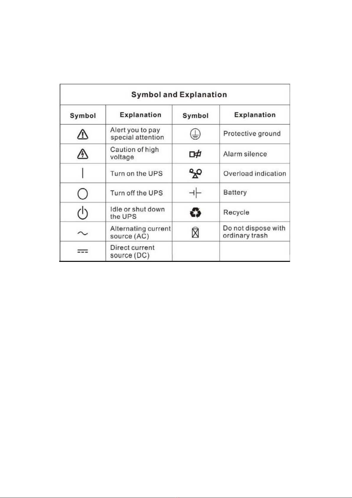
II. DESCRIPTION OF COMMONLY USED SYSMBOLS............................................................4
III. INTRODUCTION......................................................................................................................5
3.1. System and model desctription .......................................................................................5
3.2. Product specification and performance ............................................................................5
3.2.1 General specification ...............................................................................................5
3.2.2 Electrical performance.............................................................................................6
3.2.3 Operating enviroment ..............................................................................................6
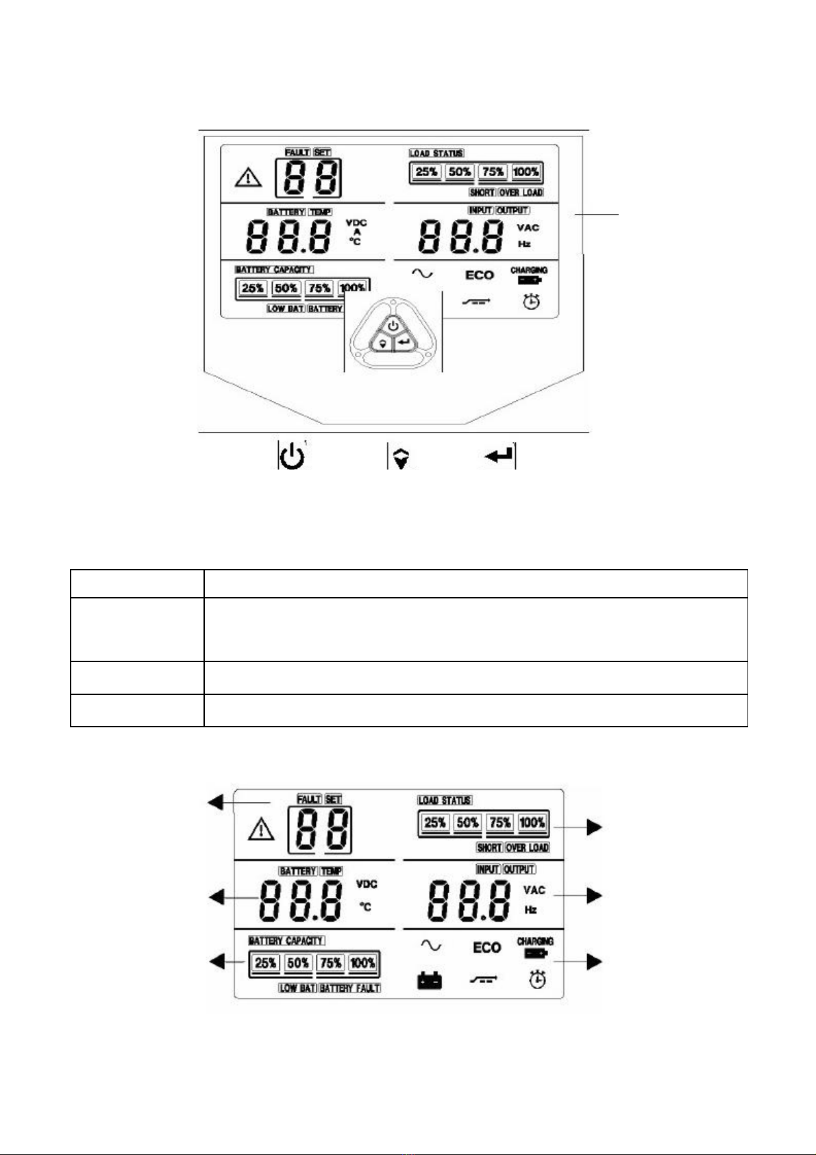
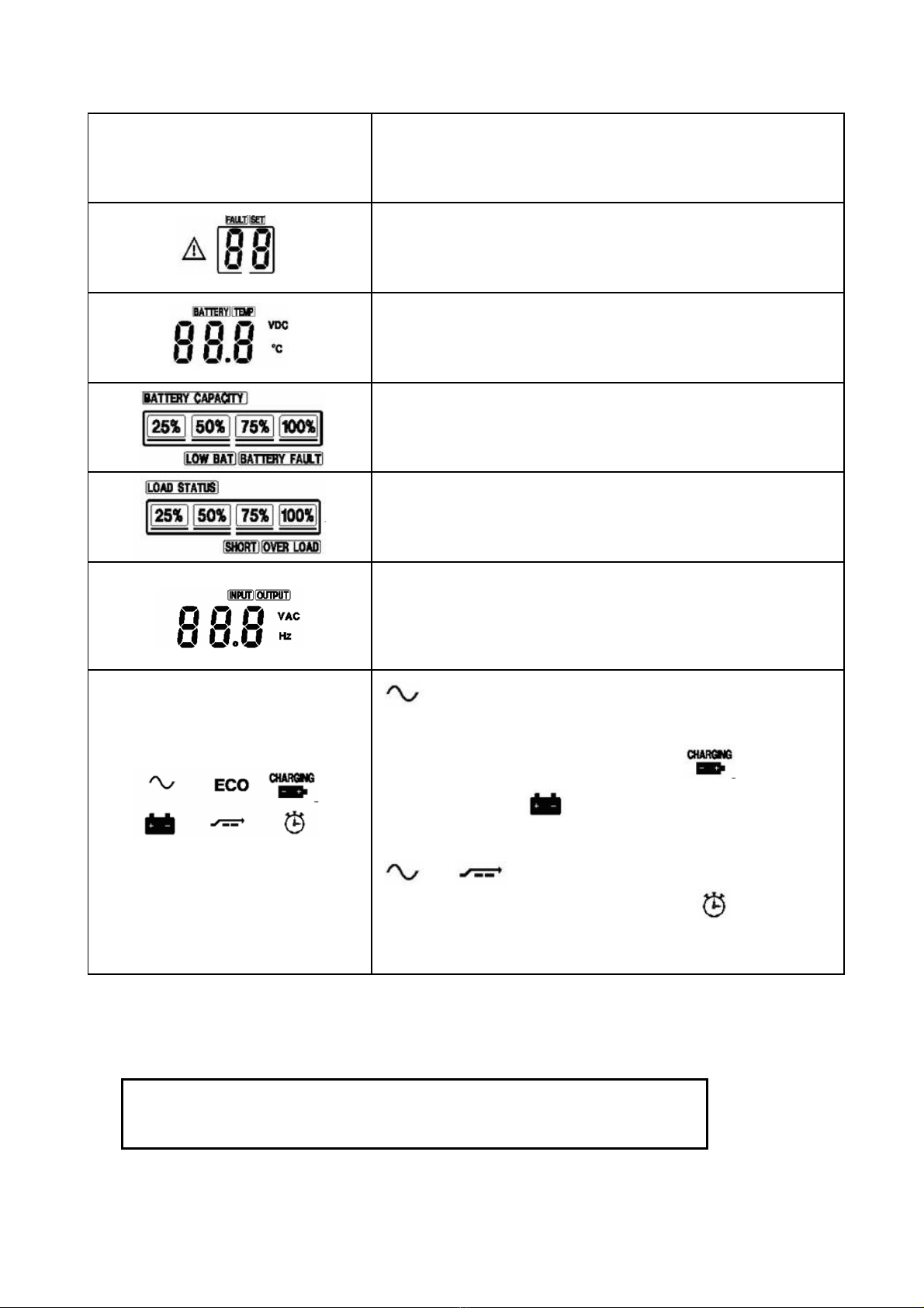
3.2.4 Dsplay panel ............................................................................................................7
3.2.5 İnstallation................................................................................................................8
IV. INSTALLATION .......................................................................................................................9
4.1. Un packing and inspection ................................................................................................9
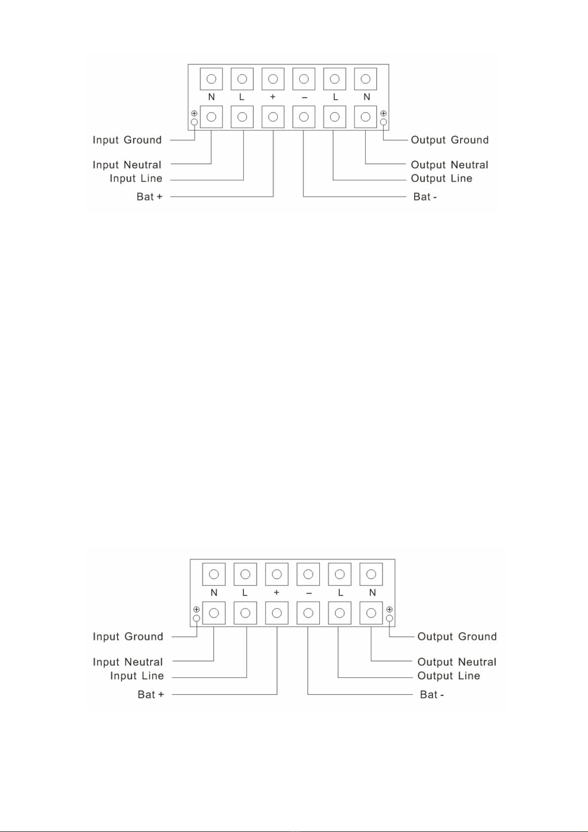
4.2. Input and output power cords and protective earth groundins tallation.............................9
4.2.1 Notes for installation ................................................................................................9
4.2.2 Installation................................................................................................................9
4.3. Opertaing procedure for connecting the long back up time model
Ups with the external bttery .....................................................................................11
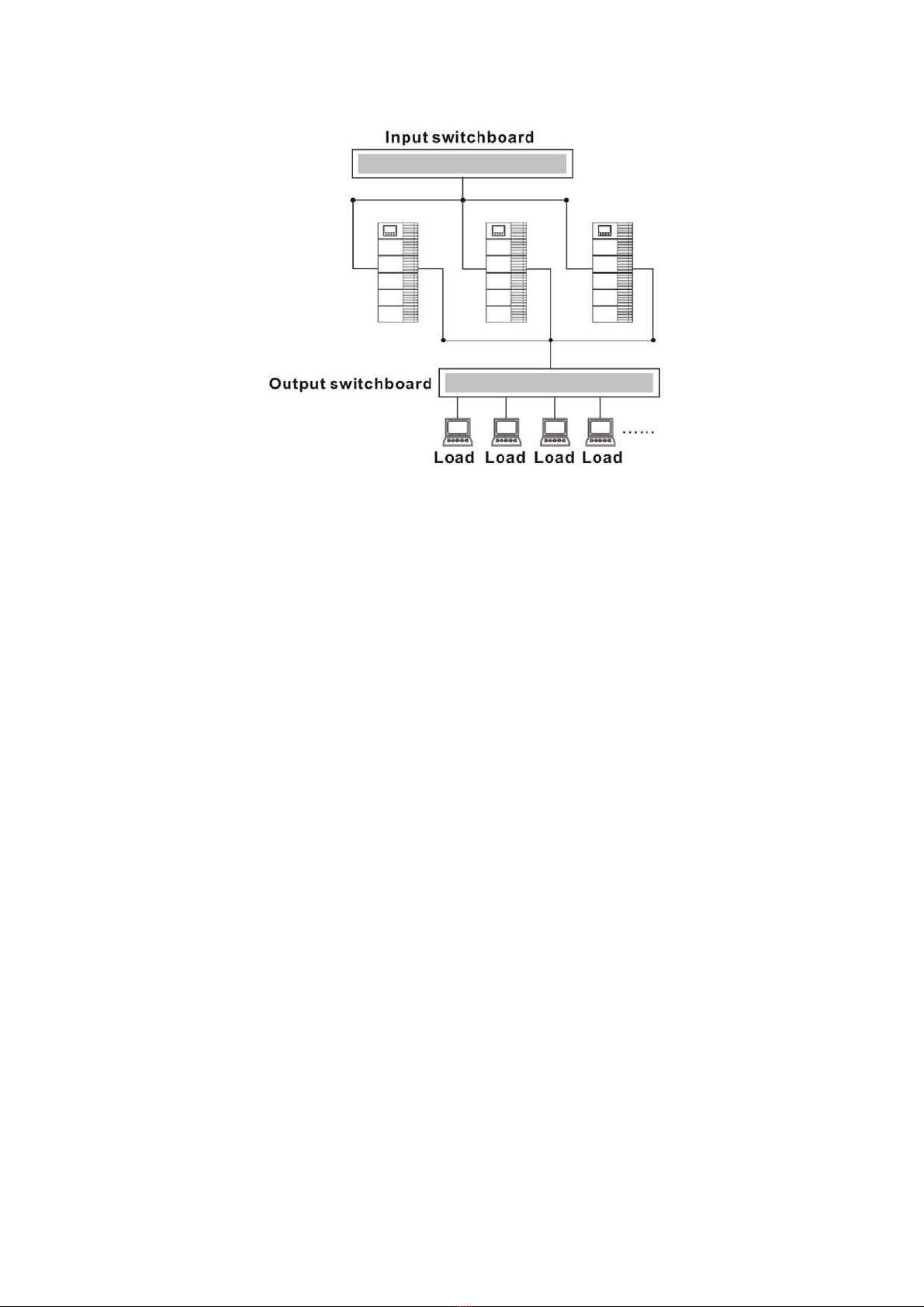
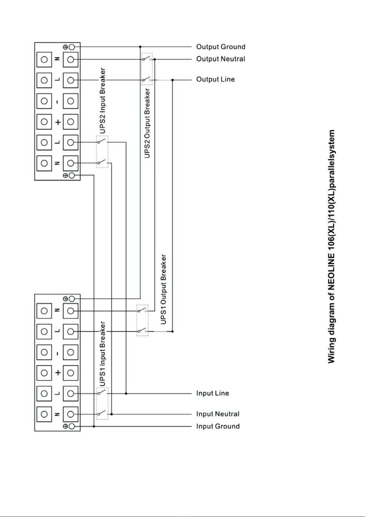
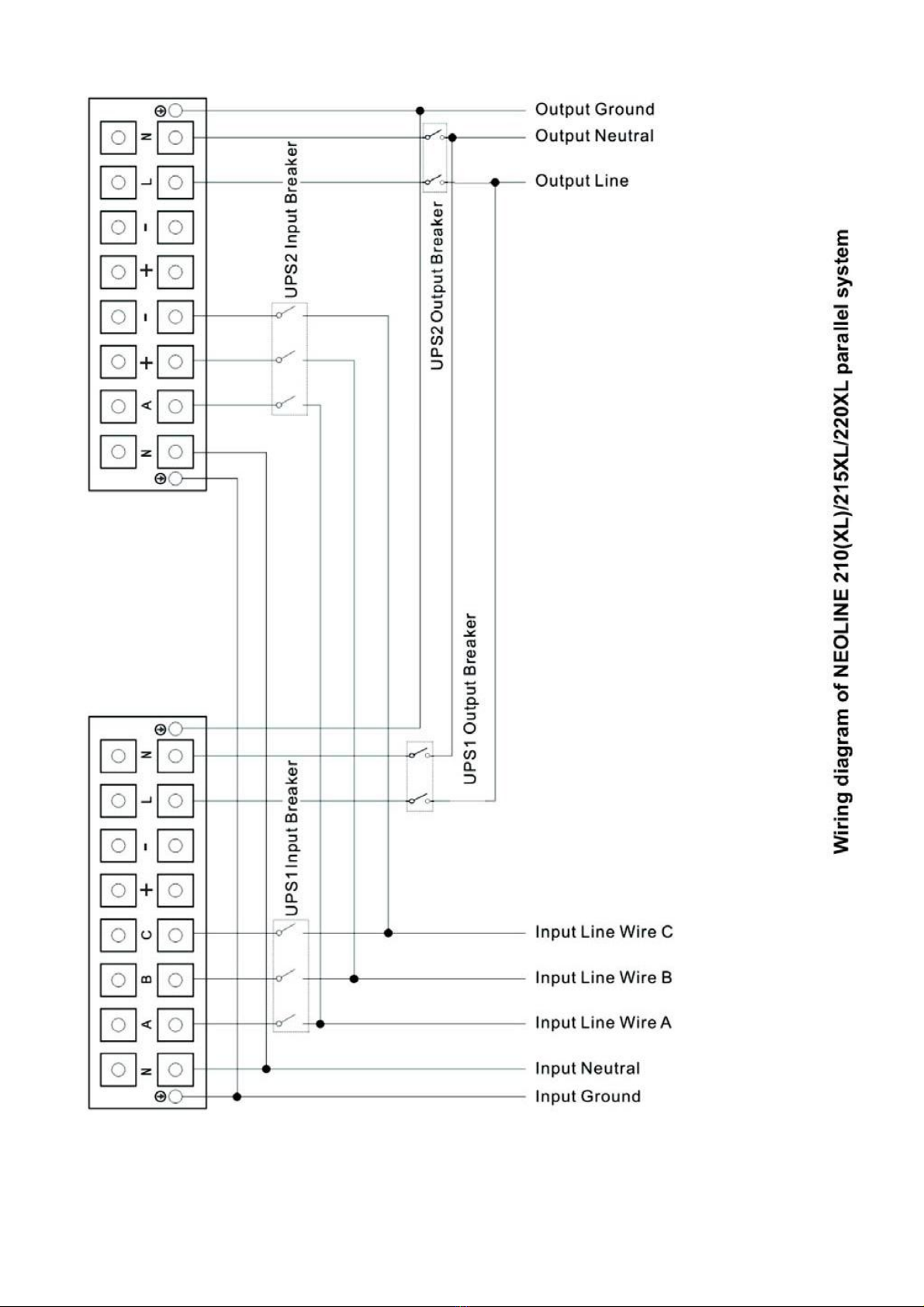
4.4. Parallel operation...............................................................................................................12
4.4.1 Briet intro duction of the redun dancy......................................................................12
4.4.2 Parallel installation...................................................................................................12
4.4.3 Operation and maintenance ....................................................................................12
V. OPERATION DEL UPS WITH THE EXTERNAL BATTERY...................................................15
6.1. Operation mode.................................................................................................................
6.2. Parallel operation...............................................................................................................
6.3. Back up time for the standard model ................................................................................
VI. BATTERY MAINTENANCE.....................................................................................................15
VII. NOTES FOR BATTERY DİSPOSAL AND BATTERY REPLACEMENT................................15
VIII. TROUBLE SHOOTING............................................................................................................15
IX. OPERATING MODE OR ALL MODELS .................................................................................15


1
1. IMPORTANT SAFETY INSTRUCTION
1.Safety and EMC instructions
Please read carefully the following user manual and the safety instructions before installing the unit or using the
unit!
1.1 Installation
■
Condensation may occur if the UPS is moved directly from a cold to a warm environment. The UPS must be
absolutely dry before being installed. Please allow an acclimatization time of at least two hours.
■
Do not install the UPS near water or in damp environment.
■
Do not install the UPS where it would be exposed to direct sunlight or near heat.
■
Do not block ventilation openings in the UPS’s housing.
■
Do not connect appliances or items of equipment which would overload the UPS (e.g. laser printers, etc) to the
UPS output.
■
Place cables in such a way that no one can step on or trip over them.
■
UPS has provided earthed terminal, in the final installed system configuration, equipotential earth bonding to
the external UPS battery cabinets.
■
An integral single emergency switching device which prevents further supply to the load by the UPS in any
mode of operation should be provided in the building wiring installation.
■
An appropriate disconnect device as short-circuit backup protection should be provided in the building wiring
installation.
■
For three-phase equipment connection to an IT power system, a four-pole device which disconnect all phase
conductors and the neutral conductor should be provided in the building wiring installation.
■
This is permanently connected equipment , it must be installed by qualified maintenance personnel.
■
Earth connection essential before connecting to the building wiring terminal.
1.2 Operation
■
Do not disconnect the earth conductor cable on the UPS or the building wiring terminals in any time since this
would cancel the protective earthing of the UPS system and of all connected loads
■
The UPS output terminal block may be electrically lived even if the UPS system is not connected to the
building wiring terminal.
■
In order to fully disconnect the UPS, first press the OFF button, then disconnect the mains lead.
■
Ensure that no liquid or other foreign objects can enter the UPS.
■
The UPS can be operated by any individuals with no previous experience.

2
1.3 Maintenance, servicing and faults
■
The UPS operates with hazardous voltages. Repairs may be carried out only by qualified maintenance
personnel.
■
Caution - risk of electric shock. Even after the unit is disconnected from the mains power supply (building
wiring terminal), components inside the UPS are still connected to the battery which are potentially dangerous.
■
Before carrying out any kind of service and/or maintenance, please disconnect the batteries. Verify that no
current is present and no hazardous voltage exists in the capacitor or BUS capacitor terminals.
■
Batteries must be replaced only by qualified personnel.
■
Caution - risk of electric shock. The battery circuit is not isolated from the input voltage. Hazardous voltages
may occur between the battery terminals and the ground. Verify that no voltage is present before servicing!
■
Batteries have a high short-circuit current and pose a risk of shock. Take all precautionary measures specified
below and any other measures necessary when working with batteries:
-remove all jewellery, wristwatches, rings and other metal objects
-use only tools with insulated grips and handles.
■
When changing batteries, replace with the same quantity and the same type of batteries.
■
Do not attempt to dispose of batteries by burning them. It could cause explosion.
■
Do not open or destroy batteries. Effluent electrolyte can cause injury to the skin and eyes. It may be toxic.
■
Please replace the fuse only by a fuse of the same type and of the same amperage in order to avoid fire
hazards.
■
Do not dismantle the UPS, except qualified maintenance personnel.
1.4 Transport
■
Please transport the UPS only in the original packaging (to protect against shock and impact).
1.5 Storage
■
The UPS must be stockpiled in the room where it is ventilated and dry.

3
1.6 Standards
* Safety
IEC/EN 62040-1-1
* EMI
Conducted Emission IEC/EN 62040-2 Category C3
Radiated Emission IEC/EN 62040-2 Category C3
*EMS
ESD IEC/EN 61000-4-2 Level 4
RS IEC/EN 61000-4-3 Level 3
EFT IEC/EN 61000-4-4 Level 4
SURGE IEC/EN 61000-4- Level 4
Low Frequency Signals IEC/EN 61000-2-2
Warning: This is a product for commercial and industrial application
in the second environment-installation restrictions or

4
2. Description of commonly used symbols
Some or all of the following symbols may be used in this manual. It is advisable to familiarize yourself with them
and understand their meaning:

5
3. Introduction
3.1 System and model description
The On-Line-Series is an uninterruptible power supply incorporating double-converter technology. It provides
perfect protection specifically for strict load. The double-converter principle eliminates all mains power
disturbances. A rectifier converts the alternating current from the socket outlet to direct current. This direct
current charges the batteries and powers the inverter. In the event of power failure, the maintenance-
free batteries power the inverter. Thus the inverter generates a sine wave AC power, which permanently
supplies the loads.
Designed with the proven on-line, double conversion architecture, this series of UPS offers the greatest degree
of availability in power protection and provides continuous high-quality AC power to connect strict load, especially
for the basic equipments in some areas as: finance, communication, government, traffic, manufacture, education
and so on.
This manual is applicable to the following models:
Type Model Input Battery
Standard 6KVA NEOLINE 106 Single phase inbuilt
10KVA NEOLINE 110 Single phase inbuilt
Long
back up
time
10KVA NEOLINE 210 Three-phase inbuilt
6KVA NEOLINE 106XL Single phase External battery bank
10KVA NEOLINE 110XL Single phase External battery bank
10KVA NEOLINE 210XL Three-phase External battery bank
15KVA NEOLINE 215XL Three-phase External battery bank
20KVA NEOLINE 220XL Three-phase External battery bank
“XL”Model: Long backup time
3.2 Product Specification and Performance
1)General specification
Power
Rating Model
Frequ
ency
(Hz)
Input(full load)Output Dimensions
(W*D*H) m
Weight
(kg)
Voltage Current
Voltage Current
6KVA/4.8K
W NEOLINE 106 50/6
0 (176-276) VAC
31max
220V/230V
27A 248×500×616
57
6KVA/4.8K
W
NEOLINE
106XL
50/6
0 (176-276) VAC
31max
220V/230V
27A 248×500×460
18
10KVA/8K
W NEOLINE 110 50/6
0 (176-276) VAC
50max
220V/230V
45A 248×500×616
67
10KVA/8K
W
NEOLINE
110XL
50/6
0 (176-276) VAC
50max
220V/230V
45A 248×500×460
20
10KVA/8K
W NEOLINE 210 50/6
0 (304-478) VAC
50max
220V/230V
45A 248×500×885
88
10KVA/8K
W
NEOLINE
210XL
50/6
0 (304-478) VAC
50max
220V/230V
45A 248×500×615
27
15KVA/12
W
NEOLINE
215XL
50/6
0 (304-478) VAC
75max
220V/230V
68A 248×500×616
35
20KVA/16
W
NEOLINE
220XL
50/6
0 (304-478) VAC
100max
220V/230V
91A 248×500×616
35

6
2)Electrical performance
INPUT
Model Voltage Frequency Power Factor
NEOLINE106XL / 110XL Single-phase
220VAC - 230VAC
50/60Hz±5%
(adjustable)>0.99(Full load)
NEOLINE 210XL
NEOLINE 215XL
NEOLINE 220XL
Three-phase
380VAC/220 VAC
380VAC/230 VAC
50/60Hz±5%
(adjustable)>0.95(Full load)
OUTPUT
Voltage
regulation
Power
factor Frequency tolerance Distortion Overload capacity Current
crest ratio
±1%
0.8
Synchronized
46-54Hz in Line mode
(AC mode) ±1% of
normal frequency in
Battery mode
THD<2%
Full load
(Linear load)
105%-125% load
transfers to bypass
mode after 1minutes
>130% load
transfers to bypass
mode after 30second
3:1
maximum
3) Operating Environment
Temperature Humidity Altitude Storage temperature
0 C-40 C <95% <1000m 0 C-40 C
Note: if the UPS is installed or used in a place where the altitude is bove than 1000m, the output power must be
derated in use, please refer to the following:
Altitude (M) 1000 1500 2000 2500 3000 3500 4000 4500 5000
Derating Power 100% 95% 91% 86% 82% 78% 74% 70% 67%

7
4. Display Panel
T
he following table describes the function of the button switches of the front panel.
Button Function
ON/OFF Button
This button has two functions:
- Turning on the UPS system: By pressing this button the UPS system turns on.
- Shut off the UPS system: When mains power is normal, the UPS System switches to
Bypass mode by pressing OFF button , and the inverter is off .
Select Button if the ups system is in bypass mode or self-test mode, the output ,frequency could be
selected by pressing Select button, and confirmed by pressing Enter button.
Enter Button if the ups system is in bypass mode or self-test mode, the output ,frequency could be
selected by pressing Select button, and confirmed by pressing Enter button.
On/Off Button
Select-Button
Enter-Button
LCD Screen
Mode/Fault/
Warni-ng code
Set type
Battery Voltage/
UPS temperature
Battery
information
Load
Information
Input/output voltage
and frequency
information
Indication of UPS
work mode

8
Display Function
FAULT lighting indicates mode code, fault code and warning
code, which could be displayed from 0 to99 ,SET lighting
indicates the set code, type V (set voltage), F (set frequency)
BATTERY lighting indicates the battery voltage value, which
could be displayed from 0 to 999Vdc;
TEMP lighting indicates the ups inside temperature, which could
be displayed from 0 to 999
℃
(The two items alternate displayed once every three seconds.)
indicates the battery capacity. For example: 25% and 50% lighting
synchronous, it means current battery capacity is 50%.
LOW BAT lighting indicates the battery is weak, and the UPS
should shut down soon,BATTERY FAULT lighting indicates
indicates the present load value. For example: 25% and 50%
lighting synchronous, it means current load is 50%.
When load 100% lighting and the OVER LOAD lighting with
warning, it means ups in overload
Indicates ups input voltage value, output voltage value, output
frequency value, which could be displayed from 0 to 999VAC
(The four items alternate displayed once every three seconds.)
208, 220 ,230,240VAC The four value of the output voltage could
be selected, 50/60HZ the two frequency value of the output
voltage could be selected.
indicates have mains power and when mode code display
02
that mean the ups working in Line mode.
ECO lighting indicates ups working in ECO Mode. Lighting
indicates ups charging,lighting and mode code display
03
that mean the ups working in battery mode.
and lighting coinstantaneous and mode code
display 03 that means UPS working in Bypass mode. and
LOW BAT lighting coinstantaneous and UPS with warning that
means Battery low voltage, the ups will would shut down soon.
5. Installation
the system may be installed and wired only by qualified
electricians in accordance with applicable safety regulations!

9
5.1 Unpacking and Inspection
1) Unpack the packaging and check the package contents. The shipping package contains:
●A UPS
●A user manual
●A communication cable
●A battery cable (for NEOLINE 106XL/110XL/210XL only
2) Inspect the appearance of the UPS to see if there is any damage during transportation. Do not turn on the unit
and notify the carrier and dealer immediately if there is any damage or lacking of some parts.
5.2 Input and output power cords and protective earth ground installation
1. Notes for installation
1) The UPS must be installed in a location with good ventilation, far away from water, inflammable gas and
corrosive agents.
2) Ensure the air vents on the front and rear of the UPS are not blocked. Allow at least 0.5m of space on each
side.
3) Condensation to water drops may occur if the UPS is unpacked in a very low temperature environment. In this
case it is necessary to wait until the UPS is fully dried inside out before proceeding installation and use.
Otherwise there are hazards of electric shock.
2. Installation
Installation and wiring must be performed in accordance with the local electric code and the following instructions
by Professional personnel. or safety, please cut off the mains power switch before installation. The battery
breaker also needs to be cut off if it is a long backup time model (“XL” model).
1) Open the terminal block cover located on the rear panel of the UPS, please refer to the appearance diagram.
2) For NEOLINE 106XL UPS, it is recommended to select the UL1015 10AWG (6mm2) wire or other insulated
wire which complies with AWG Standard for the UPS input and output wirings.
3) For NEOLINE 110XL/210XL UPS, it is recommended to select the UL1015 8AWG (10mm2) wire or other
insulated wire which complies with AWG Standard for the UPS input and output wirings.
4) For NEOLINE 215XL/220XL UPS,it is recommended to select the UL1015 6AWG (25mm2) wire or other
insulated wire which complies with AWG Standard for the UPS input and output wirings.
Note: Do not use the wall receptacle as the input power source for the UPS, as its rated current is less than the
UPS’s maximum input current. Otherwise the receptacle may be burned and destroyed.
5) Connect the input and output wires to the corresponding input
and output terminals according to the following diagram.

10
Note: you must make sure that the input and output wires and the input and output terminals are connected
tightly.
6) The protective earth ground wire refers to the wire connection between the equipment which consumes
electric equipment and the ground wire. The wire diameter of protective earth ground wire should be at least as
above mentioned for each model and green wire or green wire with yellow ribbon wire is used.
7) After having completed the installation, make sure the wiring is correct.
8) Please install the output breaker between the output terminal and the load, and the breaker should with
leakage current protective function if necessary.
9) To connect the load with the UPS, please turn off all the loads first, then perform the connection and finally
turn on the loads one by one.
10) No matter the UPS is connected to the utility power or not, the output of the UPS may have electricity. The
parts inside the unit may still have hazardous voltage after turning off the UPS. To make the UPS have no
output, power off the UPS, and then disconnect the utility power supply.
11) Suggest charging the batteries for 8 hours before use. After connection, turn the input breaker in the “ON”
position, the UPS will charge the batteries automatically. You can also use the UPS immediately without
charging the batteries first, but the backup time may be less than the standard value.
12) If it is necessary to connect the inductance load such as a monitor or a laser printer to the UPS, the start-up
power should be used for calculating the capacity of the UPS, as its start-up power consumption is too big when
it is started.
Input and Output Terminal Block wiring diagram of
NEOLINE 106XL/110XL

11
Input and Output Terminal Block wiring diagram of
NEOLINE 210XL/215XL/220XL
5.3 Operating procedure for connecting the long backup time model UPS with the external battery
1. The nominal DC voltage of external battery pack is 192VDC. Each battery pack consists of 16 pieces of 12V
maintenance free batteries in series. To achieve longer backup time, it is possible to connect multi-battery
packs, but the principle of “same voltage, same type” should be strictly followed.
2. For NEOLINE 106XL/110XL/210XL/215XL/220XL, The procedure of installing battery bank should be omplied
with strictly. Otherwise you may encounter the hazardous of electric shock..
1) A DC breaker must be connected between the battery pack and the UPS. The capacity of breaker must be
not less than the data specified in the general specification as follow.
Model NEOLINE
106
NEOLINE
106XL
NEOLINE
110
NEOLINE
110XL
NEOLINE
210
NEOLINE
210XL
NEOLINE
215XL
NEOLINE
220XL
Battery
voltage 192VDC 192VDC 192VDC 192VDC 192VDC 192VDC 192VDC 192VDC
Battery
current 34A max 34A max 56A max 56A max 46A max 46A max 70A max. 102A max
Note: 240VDC battery voltage can be choose for NEOLINE 106XL/101XL/210XL/215XL/220XL also
2) Set the battery pack breaker in “OFF” position and connect the 16 pieces of batteries in series.
3. To complete the connection by plugging the connector of the external battery cable into the external battery
socket of the UPS. Do not attempt to connect any loads to the UPS now. You should connect the input power
wire to the right position first. And then set the breaker of the battery pack in the “ON” position. After that
set the input breaker in the “ON” position. The UPS begins to charge the battery packs at the time.

12
5.4 Parallel operation
1. Brief introduction of the redundancy
N+X is currently the most reliable power supply structure. N represents the minimum UPS number that the total
load needs; X represents the redundant UPS number, i.e. the fault UPS number that the system can handle
simultaneously. The bigger the X is, the higher reliability of the power system is. For occasions where
reliability is highly required, N+X is the optimal mode. As long as the UPS is equipped with parallel cables, up to
3 of them can be connected in parallel to realize output power sharing and power redundancy.
2. Parallel installation
1) Users need to opt a standard 25-pin communication cable, which should have 25 cores, corresponding
stitches and shield, as the UPS parallel cable. The length of the parallel cable is appropriate to be less than 3 m.
2) Strictly follow the stand-alone wiring requirement to perform the input wiring of each UPS.
3) Connect the output wires of each UPS to an output breaker panel first, and then connect the wiring to the load
via the breaker panel.
4) The parallel UPS must be equipped with battery individually.
5) Please refer the figure followed to see the wiring of parallel operation. The capacity of the breaker must be not
less than the specification as follow.
Model No. Capacity of breaker
NEOLINE 106XL ≥40A/250VAC
NEOLINE 110XL/210XL ≥60A/250VAC
NEOLINE 215XL/220XL ≥100A/250VAC
*The requirement of the output wiring is as follows:
●When the distance between the UPSs in parallel and the breaker panel is less than 20 meters, the difference
between the wires of input & output of the UPSs is required to be less than 20%;
●When the distance between the UPSs in parallel and the breaker panel is greater than 20 meters, the ifference
between the wires of input & output of the UPSs is required to be less than 10%.
3. Operation and maintenance
1) To perform the general operation, follow the stand-alone operating requirement.
2) Startup: The units transfer to INV mode simultaneously as they start up sequentially in Line mode.
3) Shutdown: the units shut down sequentially in INV mode. When the last one completes the shutdown action,
each unit will shut down the inverter simultaneously and transfer to Bypass mode. It is easy to operate the
equipment, with no previous training. You just need to read through this manual and operate according to the
instructions in it.

13
Parallel Installation Diagram
4) To perform the maintenance, follow the stand-alone requirement

14

15

16
6. Operation
6.1 Operation Mode
1. Turn on the UPS with utility power supplied (in Line mode)
1) After you make sure that the power supply connection is correct, and then set the breaker of the battery pack
in the “ON” position (this step only for long backup time model), after that set the input breaker in the “ON”
position. At this time the fan rotates and the UPS supplies power to the load via the bypass. The UPS operates
in Bypass mode, the mode code is “01”.
2) To power on the UPS by simply pressing the ON button continuously for more than 1 second, the buzzer will
beep once.
3) A few seconds later, the UPS turn into Line mode, and the mode code is “02”. If the utility power is abnormal,
the UPS will operate in Battery mode without output interruption of the UPS.
2. Turn on the UPS with no utility power supplied (in Battery mode)
1) After you make sure that the breaker of the battery pack is in the “ON” position (this step only for long backup
time model).
2) Press the ON button continuously for more than 1 second to power on the UPS, and the buzzer will beep
once, UPS operates in No Output mode, the mode code is “00”.
3) A few seconds later, the UPS turn into Battery mode, and the mode code is “03”.
3. Turn off the UPS with utility power supplied (in Line mode)
1) To turn off the inverter of the UPS by pressing the OFF button continuously for more than 1 second, and the
buzzer will beep once. The UPS will turn into Bypass mode.
2) Upon completion of the above to turn it off, output of electric current of the UPS is still present. In order to cut
off the output from the UPS, simply cut off the utility power supply, a few seconds later, there are not any display
is shown on the display panel and no voltage output is available from the UPS output.
4. Turn off the UPS with no utility power supplied (in Battery mode)
1) To power off the UPS by pressing the OFF button continuously for more than 1 second, and the buzzer will
beep once.
2) When being powered off, the UPS will turn into No Output mode. Finally not any display is shown on the
display panel and no voltage is available from the UPS output.
Suggestions: Please turn off the connected loads before turning on the UPS and turn on the loads one by one
after the UPS is working in INV mode. Turn off all of the connected loads before turning off the UPS.
7. Battery Maintenance
●This series UPS only requires minimal maintenance. The battery used for standard models are value regulated
sealed lead-acid maintenance free battery. These models require minimal repairs. The only requirement is to
charge the UPS regularly in order to maximize the expected life of the battery. When being connected
to the utility power, whether the UPS is turned on or not, the UPS keeps charging the batteries and also offers
the protective function of overcharging and over-discharging.
Table of contents
Other Tescom UPS manuals

Tescom
Tescom TEOS+ 300 Series User manual

Tescom
Tescom XA-200P Series User manual

Tescom
Tescom 400 VA User manual

Tescom
Tescom DS300 Series User manual

Tescom
Tescom CL110D User manual

Tescom
Tescom DS3100T User manual

Tescom
Tescom T-300P Series User manual

Tescom
Tescom T-3250P User manual

Tescom
Tescom DXA3000 Series User manual

Tescom
Tescom XA206P User manual

Tescom
Tescom T3100P User manual

Tescom
Tescom AVR 11 User manual

Tescom
Tescom DS300SH Series User manual

Tescom
Tescom LEO LCD 650 User manual

Tescom
Tescom T-200 Series User manual

Tescom
Tescom DS300HB Series User manual

Tescom
Tescom T-310P User manual

Tescom
Tescom DS300H Series User manual

Tescom
Tescom DS310T User manual

Tescom
Tescom DS200 Series User manual