Online XANTO Series User manual

ONLINE USV-Systeme AG –Luise-Ullrich-Straße 8 –82031 Grünwald / Germany - www.online-usv.de
ONLINE USV-Systems S.r.l. - Via Ferruccio Gilera 110 - I-20862 Arcore (MB) - www.online-ups.it
ONLINE USV-Systeme AG –c/o POTESTA AG - Hertistrasse 29 - 8304 Wallisellen (Zürich) - www.online-usv.ch
\X6000-20000_quickstart-saftety_ger-engl-it_final_20170309.docx
Sicherheitsinformation
und Schnellstartanleitung für XANTO-Serie, 6000 –20000VA
Vielen Dank, dass Sie sich für ein Produkt der ONLINE USV-Systeme AG entschieden haben. Dieses
Merkblatt enthält wichtige Anweisungen, die Sie während Installation und Wartung der USV-Anlage und
der Batterien befolgen müssen. Bei Nichteinhaltung können technische Schäden sowie schwere, mit-
unter sogar tödliche Verletzungen die Folge sein. Bitte lesen Sie alle Anweisungen des Handbuches,
bevor Sie mit dem Gerät arbeiten. Das Handbuch steht zum kostenlosen Download unter www.online-
ups.com zur Verfügung.
Sicherheitsinformation
Die USV-Anlage führt lebensgefährliche Spannungen. Alle Reparatur- und Wartungsarbeiten soll-
ten nur von Kundendienstfachleuten durchgeführt werden
Die USV-Anlage enthält eine eigene Energiequelle (Batterien). Der Ausgang der USV-Anlage kann
Spannung führen, auch wenn die USV-Anlage nicht an eine Wechselstromquelle angeschlossen
ist
Um Brandgefahr oder das Risiko eines elektrischen Schlages zu verringern, darf die USV-Anlage
nur in Gebäuden mit kontrollierter Temperatur und Luftfeuchtigkeit installiert werden, in denen
keine leitenden Schmutzstoffe vorhanden sind. Die Umgebungstemperatur darf 40°C nicht über-
steigen. Die USV-Anlage darf nicht in der Nähe von Wasser oder in extrem hoher Luftfeuchtigkeit
(>90%) betrieben werden
Vergewissern Sie sich vor dem Transport der USV-Anlage, dass sie von der Stromversorgung
getrennt und ausgeschaltet ist und die Batterien deaktiviert sind
Batterien können das Risiko eines elektrischen Schlags bergen oder durch hohen Kurzschluss-
strom in Brand geraten. Bitte treffen Sie die erforderlichen Vorsichtsmaßnahmen. Die Wartung
muss von qualifiziertem Personal durchgeführt werden, das im Umgang mit Batterien geübt ist und
über gute Kenntnisse der erforderlichen Vorsichtsmaßnahmen verfügt. Halten Sie nicht autorisier-
tes Personal von Batterien fern
Die Batterien müssen ordnungsgemäß entsorgt werden. Hierbei sind die örtlichen Bestimmungen
zu beachten
Batterien dürfen nicht verbrannt werden. Es besteht Explosionsgefahr
XANTO 6000 /
10000
Batteriepaket für
XANTO
6000 - 10000
XANTO 10000 3/1
XANTO 20000 3/1
Batteriepaket für
XANTO 10000 3/1
–20000 3/1
19"-Montagewinkel (links und rechts)
2
2
Füße für Towermontage (Sets)
2
Verlängerung für Füße Towermontage
2
USB-Schnittstellenkabel
1
1
1
1
Parallelkabel
1
1
1
1
Synchronisationskabel (share current)
1
1
1
1
Batteriekabel
1
1
1
Schnellstartanleitung
1
1
1
1
1
DataWatch-Software*
Handbuch*
*Download unter www.online-ups.com

ONLINE USV-Systeme AG –Luise-Ullrich-Straße 8 –82031 Grünwald / Germany - www.online-usv.de
ONLINE USV-Systems S.r.l. - Via Ferruccio Gilera 110 - I-20862 Arcore (MB) - www.online-ups.it
ONLINE USV-Systeme AG –c/o POTESTA AG - Hertistrasse 29 - 8304 Wallisellen (Zürich) - www.online-usv.ch
\X6000-20000_quickstart-saftety_ger-engl-it_final_20170309.docx
Inbetriebnahme
1. 19“-Rackinstallation (nur XANTO 6000 / 10000)
Passen Sie die Displayausrichtung der USV-Anlage dem liegenden Rackeinbau an. Entfernen Sie
hierzu die Frontblende, indem Sie diese nach vorne ziehen. Drücken Sie anschließend die Plastik-
klammern am Display auseinander, um es aus der Befestigung zu lösen. Drehen Sie es um 90 Grad
und stecken Sie es wieder in die Frontblende. Montieren Sie im Anschluss die Frontblende in umge-
kehrter Reihenfolge.
2. Mechanische Installation
Stellen Sie die USV-Anlage auf eine ebene, stabile Oberfläche an ihren endgültigen Platz. Bei den
Rack-Tower-Kombimodellen gehen Sie gemäß den nachfolgenden Abbildungen vor:
Rack-Tower-Kombimodell als Tower
Rack-Tower-Kombimodell im 19“-Rack
3. Elektrische Installation
ACHTUNG
Die USV-Anlage führt lebensgefährliche Spannungen. Alle Reparatur- und Wartungsarbeiten
sollten nur von Kundendienstfachleuten durchgeführt werden
Schließen Sie zuerst immer den Schutzleiter an
Beachten Sie die regionalen Gesetze und Regeln zum Anschluss elektrischer Geräte

ONLINE USV-Systeme AG –Luise-Ullrich-Straße 8 –82031 Grünwald / Germany - www.online-usv.de
ONLINE USV-Systems S.r.l. - Via Ferruccio Gilera 110 - I-20862 Arcore (MB) - www.online-ups.it
ONLINE USV-Systeme AG –c/o POTESTA AG - Hertistrasse 29 - 8304 Wallisellen (Zürich) - www.online-usv.ch
\X6000-20000_quickstart-saftety_ger-engl-it_final_20170309.docx
Empfohlene Kabelquerschnitte :
XANTO
6000
XANTO
10000
XANTO
10000 3/1
XANTO
20000 3/1
Eingang
6mm2
10mm2
10mm2
16mm2
Ausgang
6mm2
10mm2
10mm2
16mm2
Schutzleiter
6mm2
10mm2
10mm2
16mm2
Anschlussschraube
M5
M5
M5
M6
Kabelschuh, außen max.
10mm
10mm
12mm
18mm
Sicherung im Batteriepa-
ket
50A
50A
100A
100A
Entfernen Sie die Abdeckung der Klemmleiste und schließen Sie die Leitungen gemäß der Abbil-
dungen an:
Abbildung 1: Klemmleiste XANTO 6000 / 10000
Abbildung 2: Klemmleiste XANTO 10000 3/1
Abbildung 3: Klemmleiste XANTO 20000 3/1

ONLINE USV-Systeme AG –Luise-Ullrich-Straße 8 –82031 Grünwald / Germany - www.online-usv.de
ONLINE USV-Systems S.r.l. - Via Ferruccio Gilera 110 - I-20862 Arcore (MB) - www.online-ups.it
ONLINE USV-Systeme AG –c/o POTESTA AG - Hertistrasse 29 - 8304 Wallisellen (Zürich) - www.online-usv.ch
\X6000-20000_quickstart-saftety_ger-engl-it_final_20170309.docx
4. Verbraucher anschließen
Achtung: Die USV-Anlagen XANTO 10000 3/1 und 20000 3/1 verfügen über zwei Gruppen von Aus-
gangssteckdosen. Kritische Verbraucher sollten nicht an die programmierbaren Ausgangssteckdo-
sen angeschlossen werden.
5. Batteriepaket anschließen
Die USV-Anlagen XANTO 6000, 10000 und 20000 3/1 verfügen über keine interne Batterie. Zum
Betrieb ist mindestens ein Batteriepaket erforderlich. Für die Installation von ein oder mehr Batte-
riepaketen verbinden Sie deren Ausgang „VDC Output“ mit dem Eingang „VDC Input“ des vorgela-
gerten Batteriepaketes. Das direkt an die USV-Anlage angeschlossene Batteriepaket verbinden Sie
mit dem Eingang „VDC Input“ der USV-Anlage, bzw. mit dem Klemmenblock bei XANTO 20000 3/1.
Schalten Sie die Batteriesicherung an der Rückseite der Batteriepakete ein.
Stellen Sie die Anzahl der verwendeten Batteriepakete im Menü Nr. 7 ein (s. Handbuch Kapitel 4.4).
6. USV-Anlage mit Netzspannung versorgen
Stecken Sie das Netzanschlusskabel des Verbrauchers in eine Steck-
dose. Schalten Sie den Eingangsschalter auf der Rückseite der USV-An-
lage ein. Das Display der USV-Anlage leuchtet auf und zeigt „Sb“ an.
7. USV-Anlage einschalten
Halten Sie die Taste „ON / / “ an der USV-Anlage so lang gedrückt,
bis ein akustisches Signal ertönt. Die USV-Anlage führt einen Selbsttest
durch, signalisiert nach dessen Abschluss im Display „OK“ und arbeitet
im Normalbetrieb.
8. Falls ein zusätzlicher Notaus-Schalter installiert wurde, muss die Notaus-Funktion geprüft werden.
9. Schalten Sie die Verbraucher der Reihe nach ein.
Das ausführliche Benutzerhandbuch steht unter www.online-ups.com zum kostenlosen Down-
load zur Verfügung.

ONLINE USV-Systeme AG –Luise-Ullrich-Straße 8 –82031 Grünwald / Germany - www.online-usv.de
ONLINE USV-Systems S.r.l. - Via Ferruccio Gilera 110 - I-20862 Arcore (MB) - www.online-ups.it
ONLINE USV-Systeme AG –c/o POTESTA AG - Hertistrasse 29 - 8304 Wallisellen (Zürich) - www.online-usv.ch
\X6000-20000_quickstart-saftety_ger-engl-it_final_20170309.docx
Safety information
and quick start guide for the XANTO series, 6000 - 20000VA
Thank you for choosing a product from ONLINE USV-Systeme AG. This sheet contains important in-
structions that you must follow during the installation and maintenance of the UPS system and the bat-
teries. Failure to comply can cause serious technical damage, serious injuries or even death. Please
read all the instructions in the manual before working with the device. The manual is available to down-
load free at www.online-ups.com.
Safety information
The UPS system carries life-threatening voltages. All repair and maintenance work must be carried
out by customer service personnel.
The UPS system has its own energy source (batteries). The output of the UPS system can be live
even when the UPS system is not connected to a source of alternating current.
In order to reduce the risk of fire or electric shock, the UPS system may only be installed in buildings
with controlled temperature and air humidity in which there are no conductive contaminants. The
ambient temperature must not exceed 40°C. The UPS system must not be operated near water or
in extremely high air humidity (>90%).
Before transporting the UPS system, make sure that it is disconnected from the power supply and
switched off and that the batteries are deactivated.
Batteries can pose a risk of electric shock or catch fire as a result of high short circuit current.
Please take the necessary precautionary measures. Maintenance must be carried out by qualified
personnel who are trained in handling batteries and have good knowledge of the necessary pre-
cautionary measures. Keep unauthorised personnel away from batteries
Batteries must be disposed of properly. Local regulations must be taken into consideration.
Batteries must not be burnt. There is risk of explosion.
XANTO 6000 /
10000
Battery pack for
XANTO
6000 - 10000
XANTO 10000 3/1
XANTO 20000 3/1
Battery pack for
10000 3/1 –
20000 3/1
19"mounting bracket (left and right)
2
2
Feet for tower mounting (sets)
2
Extension for feet for tower fitting
2
USB interface cable
1
1
1
1
Parallel cable
1
1
1
1
Synchronisation cable (share current)
1
1
1
1
Battery cable
1
1
1
Quick start guide
1
1
1
1
1
DataWatch software*
Manual*
*Download from www.online-ups.com
Getting started
1. 19” rack installation (XANTO 6000 / 10000 only)
Adjust the display direction of the UPS system for horizontal rack installation. To do this, remove the
front panel by pulling it forward. Then push the plastic catches on the display apart to release it.

ONLINE USV-Systeme AG –Luise-Ullrich-Straße 8 –82031 Grünwald / Germany - www.online-usv.de
ONLINE USV-Systems S.r.l. - Via Ferruccio Gilera 110 - I-20862 Arcore (MB) - www.online-ups.it
ONLINE USV-Systeme AG –c/o POTESTA AG - Hertistrasse 29 - 8304 Wallisellen (Zürich) - www.online-usv.ch
\X6000-20000_quickstart-saftety_ger-engl-it_final_20170309.docx
Rotate it 90 degrees and insert it back into the front panel. Finally, fit the front panel by reversing the
sequence.
2. Mechanical installation
Position the UPS system on an even, stable surface for its final location. For the rack tower versa-
tile models, proceed as shown in the diagrams below:
Rack tower versatile model as a tower
Rack tower versatile model in 19” rack
3. Electrical installation
CAUTION
The UPS system carries life-threatening voltages. All repair and maintenance work must be
carried out by customer service personnel.
Always connect the earth conductor first.
Comply with regional legislation and rules on connecting electrical devices.

ONLINE USV-Systeme AG –Luise-Ullrich-Straße 8 –82031 Grünwald / Germany - www.online-usv.de
ONLINE USV-Systems S.r.l. - Via Ferruccio Gilera 110 - I-20862 Arcore (MB) - www.online-ups.it
ONLINE USV-Systeme AG –c/o POTESTA AG - Hertistrasse 29 - 8304 Wallisellen (Zürich) - www.online-usv.ch
\X6000-20000_quickstart-saftety_ger-engl-it_final_20170309.docx
Recommended cable cross sections:
XANTO
6000
XANTO
10000
XANTO
10000 3/1
XANTO
20000 3/1
Input
6mm2
10mm2
10mm2
16mm2
Output
6mm2
10mm2
10mm2
16mm2
Earth conductor
6mm2
10mm2
10mm2
16mm2
Connection fittings
M5
M5
M5
M6
Cable lug, external max.
10mm
10mm
12mm
18mm
Fuse in battery pack
50A
50A
100A
100A
Remove the cover of the terminal strip and connect the cables as shown in the diagrams below:
Figure 1: XANTO 6000 / 10000 terminal strip
Figure 2: XANTO 10000 3/1 terminal strip
Figure 3: XANTO 20000 3/1 terminal strip

ONLINE USV-Systeme AG –Luise-Ullrich-Straße 8 –82031 Grünwald / Germany - www.online-usv.de
ONLINE USV-Systems S.r.l. - Via Ferruccio Gilera 110 - I-20862 Arcore (MB) - www.online-ups.it
ONLINE USV-Systeme AG –c/o POTESTA AG - Hertistrasse 29 - 8304 Wallisellen (Zürich) - www.online-usv.ch
\X6000-20000_quickstart-saftety_ger-engl-it_final_20170309.docx
4. Connecting load
Attention: The XANTO 10000 3/1 and 20000 3/1 UPS systems have two groups of output sockets.
Critical loads should not be connected to the programmable output sockets.
5. Connecting battery pack
The XANTO 6000, 10000 and 20000 3/1 UPS systems have no internal battery. To operate them, at
least one battery pack is required. To install one or more battery packs, connect their “VDC Output”
to the “VDC Input” of the upstream battery pack. The battery pack connected directly to the UPS
system is connected to the “VDC Input” on the UPS system or the terminal block on the XANTO
20000 3/1. Switch on the battery fuse on the back of the battery pack.
Enter the number of battery packs used in menu no. 7 (see manual Chapter 4.4).
6. Supply the UPS system with utility power
Plug the mains connection cable of the load into a wall outlet socket.
Switch on the input switch on the back of the UPS system. The display
on the UPS system shows “Sb”,
7. Switching on the UPS system
Hold the “ON / / ” button on the UPS system down until you hear a
short beep. The UPS system carries out a self-test, after which “OK” ap-
pears on the display and continues in normal mode.
8. If an additional emergency stop switch has been installed, the emergency stop function needs to be
tested.
9. Switch the load on one by one.
The comprehensive user manual is available to download free at www.online-ups.com.

ONLINE USV-Systeme AG –Luise-Ullrich-Straße 8 –82031 Grünwald / Germany - www.online-usv.de
ONLINE USV-Systems S.r.l. - Via Ferruccio Gilera 110 - I-20862 Arcore (MB) - www.online-ups.it
ONLINE USV-Systeme AG –c/o POTESTA AG - Hertistrasse 29 - 8304 Wallisellen (Zürich) - www.online-usv.ch
\X6000-20000_quickstart-saftety_ger-engl-it_final_20170309.docx
Informazioni di sicurezza e guida rapida per la serie XANTO, 6000 –20000VA
Grazie per aver scelto un prodotto di ONLINE USV-Systeme AG. La presente scheda contiene istruzioni
importanti da osservare durante l’installazione e la manutenzione dell’UPS e delle batterie. La mancata
osservanza di queste istruzioni può causare danni tecnici, nonché lesioni gravi e talora mortali. Prima
di lavorare con l’apparecchiatura, leggere tutte le istruzioni fornite nel manuale. Il manuale può essere
scaricato gratuitamente da www.online-ups.com.
Informazioni di sicurezza
All’interno dell’UPS sono presenti tensioni molto pericolose. Tutti gli interventi di riparazione e ma-
nutenzione devono essere eseguiti esclusivamente da personale qualificato del Servizio di Assist-
enza Clienti.
L’UPS contiene una propria sorgente di energia (batterie). L’uscita dell’UPS può erogare tensione
anche quando l’ingresso non è collegato a una sorgente di corrente alternata.
Per ridurre al minimo il pericolo di incendio o il rischio di scossa elettrica, il sistema UPS può essere
installato solo in edifici a temperatura e umidità controllate, privi di sostanze conduttive e inquinanti.
La temperatura ambiente non deve essere superiore a 40°C. Il sistema UPS non deve essere
azionato in prossimità di acqua o in presenza di umidità atmosferica estremamente elevata (>
90%).
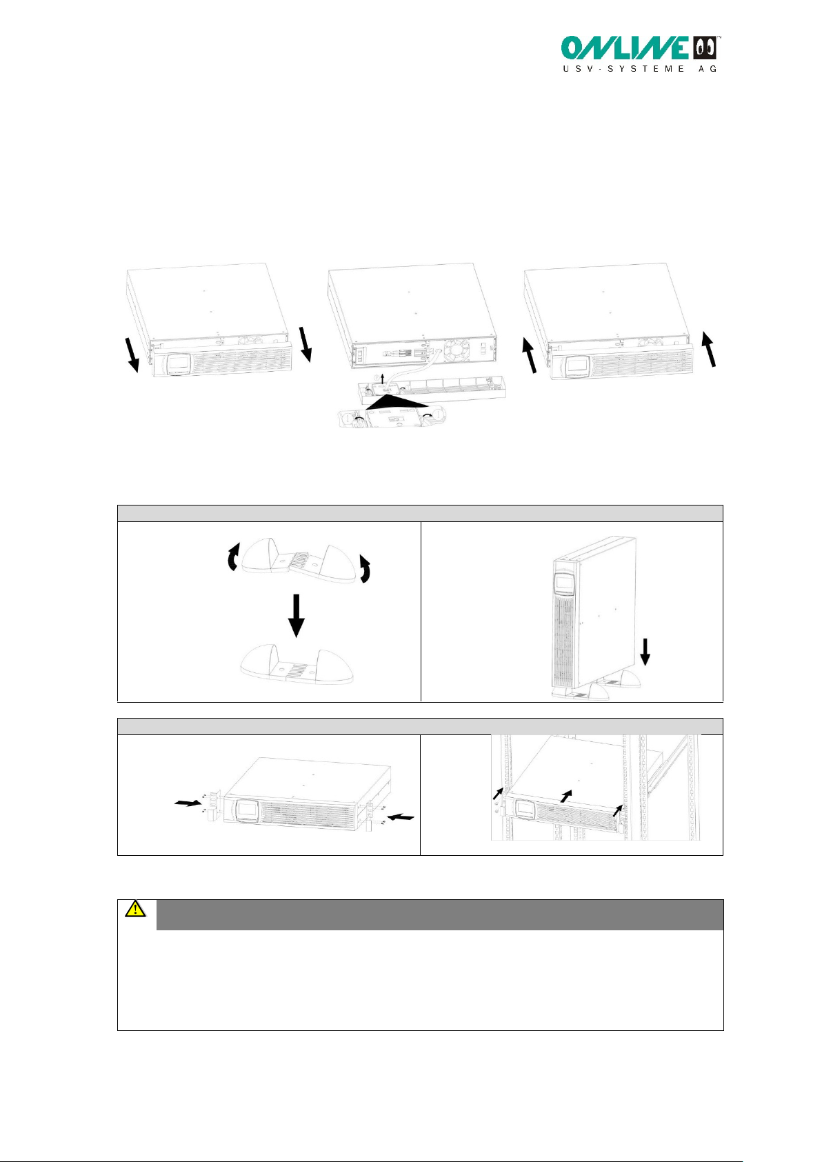
Prima di trasportare l’UPS assicurarsi che questo sia scollegato dall’alimentazione elettrica e
spento e che le batterie siano disconnesse, vedi sotto “attivare la batteria”) .
Le batterie possono celare il rischio di scossa elettrica o incendiarsi a causa di un’elevata corrente
di cortocircuito. Adottare le misure di precauzione necessarie. La manutenzione deve essere ese-
guita da personale qualificato che abbia familiarità con le batterie e che conosca bene le misure di
precauzione necessarie. Tenere il personale non autorizzato lontano dalle batterie.
Le batterie devono essere smaltite conformemente alle disposizioni di legge. A tal fine, osservare
le norme locali vigenti in materia.
Le batterie non devono essere bruciate. In tal caso sussiste il pericolo di esplosione.
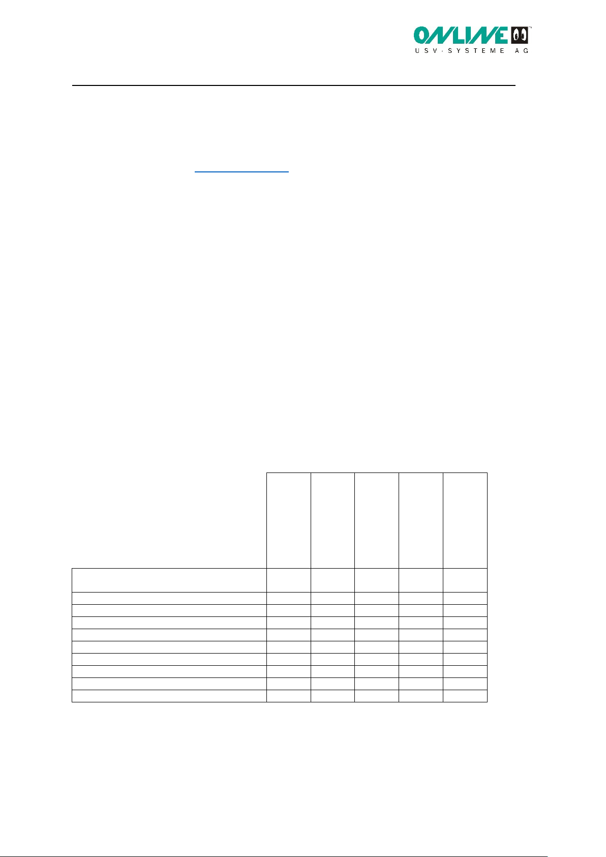
XANTO 6000 /
10000
Pacco batterie per
XANTO
6000 / 10000
XANTO 10000 3/1
XANTO 20000 3/1
Pacco batterie per
XANTO 10000 3/1
–20000 3/1
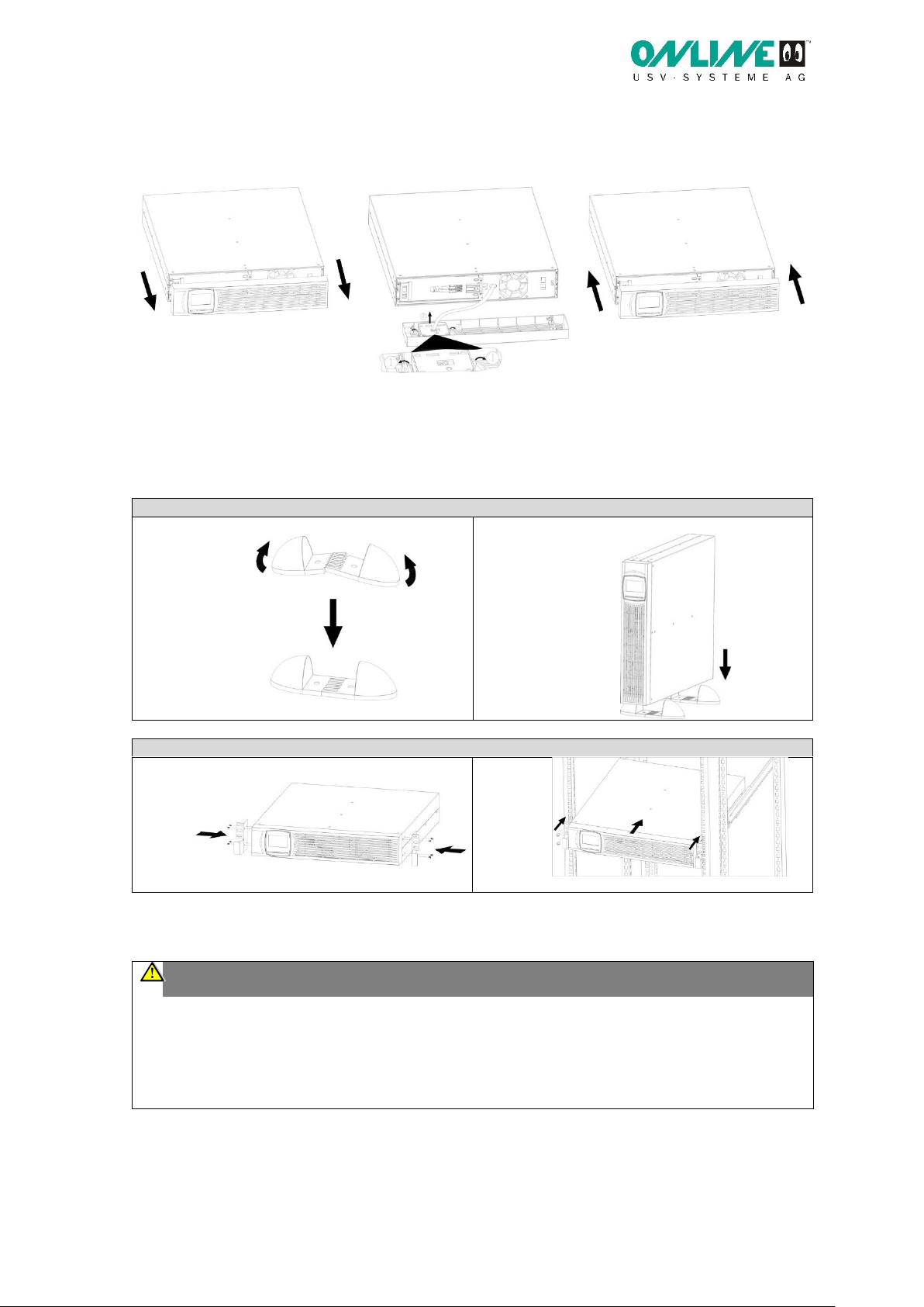
Staffe di montaggio 19” (sinistra e de-
stra)
2
2
Piedi per montaggio Tower (set)
2
Prolunga piedi per montaggio Tower
2
Cavo d’interfaccia USB
1
1
1
1
Cavo parallelo
1
1
1
1
Cavo di sincronizzazione (share current)
1
1
1
1
Cavo batteria
1
1
1
Guida rapida
1
1
1
1
1
Software DataWatch*
Manuale*
*Download da www.online-ups.com

ONLINE USV-Systeme AG –Luise-Ullrich-Straße 8 –82031 Grünwald / Germany - www.online-usv.de
ONLINE USV-Systems S.r.l. - Via Ferruccio Gilera 110 - I-20862 Arcore (MB) - www.online-ups.it
ONLINE USV-Systeme AG –c/o POTESTA AG - Hertistrasse 29 - 8304 Wallisellen (Zürich) - www.online-usv.ch
\X6000-20000_quickstart-saftety_ger-engl-it_final_20170309.docx
Messa in funzione
1. Installazione in rack da 19” (solo XANTO 6000 / 10000)
Regolare l’orientamento del display dell’UPS per il montaggio orizzontale in rack. Rimuovere a tal
fine il pannello frontale, tirandolo in avanti. Premere quindi sulle clip di plastica di fissaggio per libe-
rare il display, girare quest’ultimo di 90 gradi e inserirlo nuovamente nel pannello frontale. Rimontare
infine il pannello frontale in sequenza inversa.
2. Installazione meccanica
Posizionare il sistema UPS su una superficie piana e stabile, nella sua collocazione finale. Nei mo-
delli combi Rack-Tower procedere come illustrato nelle figure seguenti:
Modello combi Rack-Tower come Tower
Modello combi Rack-Tower in rack da 19”
3. Installazione elettrica
ATTENZIONE
All’interno dell’UPS sono presenti tensioni molto pericolose. Tutti gli interventi di riparazione
e manutenzione devono essere eseguiti esclusivamente da personale qualificato del Servizio
di Assistenza Clienti.
Collegare sempre prima il conduttore di terra.
Osservare le leggi e i regolamenti regionali sul collegamento di apparecchiature elettriche.

ONLINE USV-Systeme AG –Luise-Ullrich-Straße 8 –82031 Grünwald / Germany - www.online-usv.de
ONLINE USV-Systems S.r.l. - Via Ferruccio Gilera 110 - I-20862 Arcore (MB) - www.online-ups.it
ONLINE USV-Systeme AG –c/o POTESTA AG - Hertistrasse 29 - 8304 Wallisellen (Zürich) - www.online-usv.ch
\X6000-20000_quickstart-saftety_ger-engl-it_final_20170309.docx
Sezioni di cavo raccomandate:
XANTO
6000
XANTO
10000
XANTO
10000 3/1
XANTO
20000 3/1
Ingresso
6 mm2
10 mm2
10 mm2
16 mm2
Uscita
6 mm2
10 mm2
10 mm2
16 mm2
Conduttore di terra
6 mm2
10 mm2
10 mm2
16 mm2
Vite di collegamento
M5
M5
M5
M6
Capocorda, esterno max.
10 mm
10 mm
12 mm
18 mm
Fusibile nel pacco batterie
50 A
50 A
100 A
100 A
Rimuovere il coperchio della morsettiera e collegare i cavi come indicato nelle figure seguenti:
Figura 1: morsettiera XANTO 6000 / 10000
Figura 2: morsettiera XANTO 10000 3/1
Figura 3: morsettiera XANTO 20000 3/1

ONLINE USV-Systeme AG –Luise-Ullrich-Straße 8 –82031 Grünwald / Germany - www.online-usv.de
ONLINE USV-Systems S.r.l. - Via Ferruccio Gilera 110 - I-20862 Arcore (MB) - www.online-ups.it
ONLINE USV-Systeme AG –c/o POTESTA AG - Hertistrasse 29 - 8304 Wallisellen (Zürich) - www.online-usv.ch
\X6000-20000_quickstart-saftety_ger-engl-it_final_20170309.docx
4. Collegare le utenze
Attenzione: I sistemi UPS XANTO 10000 3/1 e 20000 3/1 sono dotati di due gruppi di prese di uscita.
Non collegare utenze critiche alle prese di uscita programmabili.
5. Collegare il pacco batterie
I sistemi UPS XANTO 6000, 10000 e 20000 3/1 non sono dotati di batteria interna. Per il funziona-
mento è richiesto almeno un pacco batterie. Per l’installazione di uno o più pacchi batterie aggiuntivi,
collegare la rispettiva uscita “VDC Output” all’ingresso “VDC Input” del pacco batterie precedente.
Per l’allacciamento del pacco batterie direttamente collegato all’UPS si utilizza l’ingresso “VDC Input”
dell’UPS oppure la morsettiera nel modello XANTO 20000 3/1. Attivare il fusibile della batteria sul
lato posteriore del pacco batterie.
Impostare il numero di pacchi batterie utilizzati nel menu n. 7 (v. Manuale, sezione 4.4).
6. Collegare l’UPS alla tensione di rete
Accendere l’interruttore di ingresso sul retro dell’UPS. Il display dell’UPS
si illumina e mostra “Sb”.
7. Accendere l’UPS
Tenere premuto il tasto “ON / / ” sull’UPS finché non viene emesso
un segnale acustico. L’UPS esegue un breve test di autodiagnostica, al
termine del quale visualizza “OK” sul display, e lavora in modalità di fun-
zionamento normale.
8. Se è installato un interruttore di arresto d’emergenza aggiuntivo, è necessario verificarne il funzio-
namento.
9. Accendere le utente in sequenza.
This manual suits for next models
4
Table of contents
Languages:
Other Online UPS manuals