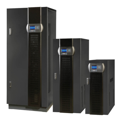
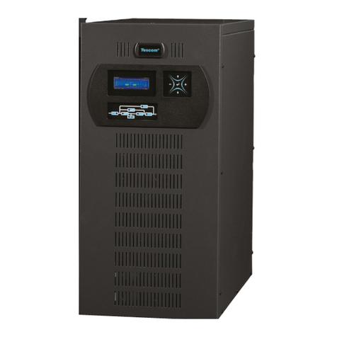
Tescom TEOS 200E PRO 10-20kVA User manual

USER MANUAL
TEOS 200E PRO 10-20kVA
Βόλου 7, 183 46 Μοσχάτο
Volou 7, 18 346, Moschato, Greece
+30 210 9590080
info@tescom-ups.gr www.tescom-ups.gr
USER MANUAL TEOS 200E PRO 10-20kVA
Βόλου 7, 183 46 Μοσχ
άτο
Volou 7, 18 346, Moschato, Greece
+30 210 9590080
info@tescom-ups.gr www.tescom-ups.gr

USER MANUAL TEOS 200E PRO 10-20kVA

USER MANUAL TEOS 200E PRO 10-20kVA

1 Product Description
Congratulations on your choice of the UPS uninterruptible power system (UPS), the UPS
comes in nominal power ratings of 6-20kVA. It is designed to provide conditioned power to
computers and other sensitive electronic equipment.
This chapter gives a brief description of the UPS, including the UPS features, models,
appearance, operating principle and specification.
1.1 Electromagnetic Compatibility
*Safety
IEC/EN 62040-1-1
*EMI
Conducted Emission ......... lEC/EN 62040-2 Category C3
Radiated Emission ............ lEC/EN 62040-2 Category C3
*EMS
ESD .................................. IEC/EN 61000-4-2 Level4
RS .................................... IEC/EN 61000-4-3 Level3
EFT .................................. IEC/EN 61000-4-4 Level4
SURGE ............................ IEC/EN 61000-4-5 Level4
Low Frequency Signals
.............. :IEC/EN 61000-2-2
Warning: This is a product for commercial and industrial application in the second
environment-installation restrictions or additional measures may be needed to prevent
disturbances.
NOTICE:
This is a product for restricted sales distribution to informed partners. Installation restrictions
or additional measures may be needed to prevent radio interference.
Operated the UPS in an indoor enviroment only in an ambient temperature range of
0-40°C(32-104°F). Install it in a clean environment, free from moisture, flammable liquids,
gases and corrosive substance.
This UPS contains no user-serviceable parts except the internal battery pack. The UPS
" �" push buttons do not electrically isolate internal parts. Under no circumstance attempt
to gain access internally, due to the risk of electric shock or burn.
Do not continue to use the UPS if the panel indications are not in accordance with these
operating instructions or the UPS performance alters in use. Refer all faults to your dealer.
Servicing of batteries should be performed or supervised by personnel knowledgeable of
batteries and the precautions. Keep unauthorized personnel away from the batteries. Proper
disposal of batteries is required. Refer to your local laws and regulations for disposal
requirement.
DO NOT CONNECT equipment that could overload the UPS or demand surge current from
the UPS, for example: electric drills, vacuum cleaners, hair dryer, motors and so on.
DO NOT CONNECT equipment that is life related, for example: medical equipment, elevator
2
USER MANUAL TEOS 200E PRO 10-20kVA

and so on.
Storing magnetic media on top of the UPS may result in data loss or corruption.
Turn off and isolate the UPS before cleaning it. Use only a soft cloth, never liquid or aerosol
cleaners.
1.2 Features
The UPS features include:
--} Providing more high efficient AC power, compared with the previous generation
--} Full digital control technology based on DSP to achieve high reliability and power
function
--} Operation and display with LCD and LED indicators, which can indicate all system
information
--} Fan speed can be auto conditioned according to the loads, input voltage or working
mode
--} Digitally controlled charger current and voltage, compared with the previous generation
which is fixed in hardware
--} Super high power density
1.3 Models
Available models are shown as Table1-1:
Table 1- 1 : Models
Model Nominal Power Model
6KH 6kVA/6kW
10KH 10kVA/10kW Long backup time
15KH 15kVA/15kW mode
20KH 20kVA/20kW
6KS 6kVA/6kW Standard time mode
10KS 10kVA/10kW
3
USER MANUAL TEOS 200E PRO 10-20kVA

1.4 Appearance
l
□
I
l1=dJ
mm
==
--
u
I I
6/10KH
i
□
i
l1=dJ
I
eJCIJCE
I
==
II
I I I I
15/20KH 6/10KS
Fig 1- 1: Front View
.. · .· ..
OJ
0 0 0
l..J
6/10KH
4
USER MANUAL TEOS 200E PRO 10-20kVA

USER MANUAL TEOS 200E PRO 10-20kVA

USER MANUAL TEOS 200E PRO 10-20kVA

This results in cleaner power being available to other devices in the building not being
protected by the UPS.
1.5.3 Inverter
In normal operation, the inverter utilizes the DC output of the power factor correction circuit
and inverters it into precise, regulated sinewave AC power. Upon a utility power failure, the
inverter receives its required energy from the battery through the DC-to-DC converter. In
both modes of operation, the UPS inverter is on-line and continuously generating clean,
precise, regulated AC output power.
1.5.4 Battery Charger
The battery charger utilizes energy from the DC bus and precisely regulates it to
continuously charge the batteries. The batteries are being charged whenever the UPS is
connected to utility power.
1.5.5 DC to DC Converter
The DC to DC converter utilizes energy from the battery system and raises the DC voltage
to the optimum operating voltage for the inverter. The converter includes boost circuit which
is also used as PFC.
1.5.6 Battery
The 6KS/10KS Standard includes value regulated, sealed lead acid, maintenance free
batteries inside. To maintain battery design life, operate the UPS in an ambient temperature
of 15-25 °C.
1.5. 7 Static Bypass
The UPS provides an alternate path for utility power to the connected load in the unlikely
event of a UPS malfunction. Should the UPS have an overload, over temperature or any
other failure condition, the UPS automatically transfers the connected load to bypass.
Bypass operation is indicated by an audible alarm and illuminated amber Bypass LED. To
manually transfer the connected load from the inverter to bypass, press the " + "
button once.
NOTICE: The bypass power path does NOT protect the connected equipment from
disturbances in the utility supply.
1.6 UPS Working Mode
Normally UPS working mode include normal mode, bypass mode, battery mode, ECO mode,
frequency converter mode, self aging mode.
Normal mode:
Shown as Fig 1-4, rectifier supply DC supply to inverter, the load is feed by inverter. Charger
is charging the battery.
7
USER MANUAL TEOS 200E PRO 10-20kVA

USER MANUAL TEOS 200E PRO 10-20kVA

working normally. The efficiency is up to 98%, but UPS can protect the load from surge
disturb. If input power is failure, UPS transfer to battery mode. Shown as
Fig 1-7.
TVS&RFI
EMI filter
Frequency Converter Mode
Fig 1- 7: ECO Mode
INV Output
...._ _ ___.
In this mode, input and output nominal frequency is different, and the bypass is forbidden to
use.
NOTICE: if overload timeout, UPS will shutdown output.
NOTICE: the load should be derated to 50% and below.
Self Aging Mode
If users want to burn in UPS without load, could set the UPS as Self Aging Mode, in this
mode, the current flow through rectifier, inverter, and back to input through bypass. It needs
only 5% loss to burn in UPS with 100% load. Shown as Fig 1-8.
1.7 Product Specification
1. General Specification
Model
Power Rating
Frequency (Hz)
Output
Fig 1- 8: Self Aging Mode
6KH/S
I
10KH/S
I
15KH
I
20KH
PF=1,kW=kVA
50/60
9
USER MANUAL TEOS 200E PRO 10-20kVA

USER MANUAL TEOS 200E PRO 10-20kVA

2 Installation
The system should be installed and wired only by qualified electricians in accordance with
applicable safety regulations.
NOTICE: UPS operation in sustained temperature outside the range of 15-25 °C (59 °-77°F)
reduces battery life.
2.1 Unpacking and Inspection
1. Unpack the packaging and check the package contents. The shipping package contains:
1 UPS
1 user manual
2. Inspect the appearance of the UPS to see if there is any damage during transportation. Do
not turn on the unit and notify the carrier and dealer immediately if there is any damage or
lacking of some parts.
2.2 Connect Input/Output Power
1. Notes for installation
(1) The UPS must be installed in a location with good ventilation, far away from water,
inflammable gas and corrosive agents.
(2) Ensure the air vents on the front and rear of the UPS are not blocked. Allow at least 0.5m of
space on each side.
(3) Condensation to water drops may occur if the UPS is unpacked in a very low temperature
environment. In this case it is necessary to wait until the UPS is fully dried inside out before
proceeding installation and use. Otherwise there are hazards of electric shock.
(4) The circuit breaker (CB) with residual current device (RCD) should not be used in the input
of UPS.
2. Installation
Installation and wiring must be performed in accordance with the local electric code and the
following instructions by professional personnel.
For safety, please cut off the mains power switch before installation. Open the battery breaker
for long backup time model ("H" model).
(1) Open the terminal block cover located on the rear panel of the UPS, please refer to the
appearance diagram.
(2) For 6/10kVA UPS, it is recommended to select the UL 1015 10/8 AWG (6/10 mm
2
) wire or
other insulated wire which complies with AWG Standard for the UPS input and output wirings.
(3) For 15/20kVA UPS, it is recommended to select the UL 1015 6/4 AWG (16/25mm
2
) wire or
other insulated wire which complies with AWG Standard for the UPS input and output wirings.
NOTICE: Do not use the wall receptacle as the input power source for the UPS, as its rated
current is less than the UPS's maximum input current. Otherwise the receptacle may be burned
and destroyed. For the long backup time modes, make sure that the capacity of batteries is 24
Ah to avoid over charging. If not, please confirm the charge current and set the charge current
11
USER MANUAL TEOS 200E PRO 10-20kVA

USER MANUAL TEOS 200E PRO 10-20kVA

To make the UPS have no output, power off the UPS, and then disconnect the utility power
supply.
(10) Suggest charging the batteries for 8 hours before use. After connection, turn the input
breaker in the "ON" position, the UPS will charge the batteries automatically. You can also use
the UPS immediately without charging the batteries first, but the backup time may be less than
the standard value.
(11) If it is necessary to connect the inductive load such as a motor or a laser printer to the UPS,
the start-up power should be used for calculating the capacity of the UPS, as its start-up power
consumption is too big when it is started.
2.3 Connect the Long Backup Time Model UPS with the External Battery
1. The nominal DC voltage of external battery pack is 192 Vdc. Each battery pack consists of
16 pieces of 12 V maintenance free batteries in series. To achieve longer backup time, it is
possible to connect multi-battery packs, but the principle of "same voltage, same type" should
be strictly followed.
2. For UPS 6/10KH, select the UL 1015 10/8 AWG (6/10 mm 2). For UPS 15/20KH, select 6/4
AWG (16/25 mm 2) wire or other insulated wire which complies with UL Standard for the UPS
battery wirings. The procedure of installing battery bank should be complied with strictly.
Otherwise you may encounter the hazardous of electric shock.
(1) A DC breaker must be connected between the battery pack and the UPS. The capacity of
breaker must be not less than the data specified in the general specification.
(2) Set the battery pack breaker in
"OFF"
position and connect the 16 pieces of batteries in
series.
(3) You must connect the external battery cable to the battery first, if you connect the cable to
the UPS first, you may encounter the hazardous of electric shock. The positive pole of the
battery is connected to the UPS with red wire; the negative pole of the battery is connected to
the UPS with black wire; the green and yellow ribbon wire is connected to the ground of the
battery cabinet.
3. To complete the connection of the external battery cable into the UPS. Do not attempt to
connect any loads to the UPS now. You should connect the input power wire to the right
position first. And then set the breaker of the battery pack in the "ON" position. After that set the
input breaker in the "ON" position, the UPS begins to charge the battery packs at the time.
2.4 Connect Parallel Cables
1. Brief introduction
As long as the UPS is equipped with parallel cables, up to 4 UPSs can be connected in parallel
to realize output power sharing and power redundancy. The unit ID in paralleled system must
be set to be different.
2. Parallel installation
(1) Users need to opt two standard 15-pin communication cables which length is appropriate to
be less than 3 m.
13
USER MANUAL TEOS 200E PRO 10-20kVA

USER MANUAL TEOS 200E PRO 10-20kVA

UPS1# UPS2#
Fig 2- 3: 2 UPS Paralleled System
If there are 3 UPS are paralleled, connect communication cables as Fig 2-4.
UPS 1# UPS2# UPS3#
Fig 2- 4: 3 UPS Paralleled System'
NOTICE: must set the UPS is parallel system as "parallel mode" via software according to
"Annex A:' before start parallel system
15
USER MANUAL TEOS 200E PRO 10-20kVA

3 Controls And Indicators
Description of Panel
Controls
......
DD□[
,-TEST/MUTE
D-<>N-c::::J-oFF-D
..... ◄ ►
Fig 3- 1
: Display Panel
Description
1.
Press " .....a" to power on the UPS from
utility power.
NOTE
battery without
Not available when UPS is set in automatically start mode
2. Press" .....a+ "to start inverter when rectifier is OK
3. Press " .....a + " to start the ups from battery without
utility
4. Press " .....a" to confirm setting when in setting mode
5. Press and hold" .....a "lo enter or exit the selling mode
6. Press and hold " ......., + "to enter the self-test mode when
ups is normal, otherwise to mute off the alarm, press and hold
again to mute on.
1. Press " " to page up the LCD menu
2. Press and hold " " to enter or exit the history inquiry
interface
3. Press "+ " to shutdown inverter and transfer to
bypass
4. Press "+ " to shutdown UPS completely when UPS
16
USER MANUAL TEOS 200E PRO 10-20kVA

1.
2.
3.
4.
Indicators
INV
BAT
BYP
FAULT
Value display
and
setting area
is in battery mode
1. Press " " to page down the LCD menu
2. Press and hold " "to fault clear
Description
Inverter indicator: green--inverter is normal, green
flicker-rectifier or inverter is starting or tracking with
bypass(ECO), dark-rectifier and inverter is not working
Battery indicator: yellow-battery discharged, yellow
flicker-No battery or battery alarm, dark-battery is
connected
Bypass indicator: yellow-bypass is normal, yellow
flicker-bypass is abnormal and alarm ,dark-UPS is in normal
mode and bypass is normal
FAULT indicator: red-UPS is abnormal, red flicker-UPS
alarm ,dark-UPS is normal
Fan
Load capacity Buzzer Fault Battery capacity
rico/n
}Z\\f)'\
HZ
JINPIU':' EAT':'IEGEY OUT!P'JT LOAD TEM!P'
Fig 3- 2: LCD Menu
Ou
Operation
bo---
mode
LCD display is divided into three areas: Icons display area, value display and settings area,
and operation mode area.
Icons display area:
There are following contents in the area of display page
Load and battery icons indicate load and battery capacity, and each square
represents 25% of capacity. Load icon will flash when UPS is overloaded; battery
icon will flash when battery capacity is too low or the battery is not connected.
Fan icon indicates the working status of fans. Normally, the fan shows rotation
status. The icon will flash if fans are disconnected or faulty;
Buzzer icon indicates if the buzzer is mute. Normally, this icon doesn't display.
Press and hold the " ......., + " buttons in battery or fault mode or set monitoring
software to set MUTE ON in any mode, the UPS will get into mute status and the
17
USER MANUAL TEOS 200E PRO 10-20kVA

buzzer icon will be illuminated.
►Fault icon is illuminated in fault mode, it doesn't display in other cases.
Value display and settings area:
♦The area of menu setting page showing the settable menu options
♦The area of event log query page showing page number of history records
►In non-setting interface, it indicates the relevant information of UPS. Press the
" ◄ " or " ► " button to display input voltage and frequency, output voltage and
frequency, battery voltage and capacity, pieces of battery, load, temperature,
software version, etc.
►The fault code will be displayed in fault mode.
►In menu setting interface, include rate voltage value (OPU), physical address(ld),
parallel Enable (PAL), Expert mode (EP), Battery numbers(PCS),Emergency
power off (EPO),etc.
Operation mode area:
►After starting up in 5 seconds, this display area mainly indicates the UPS power
rating. This function is settable.
►This display area mainly indicates the UPS operation mode in 20 seconds after
starting up, such as stdby (Standby mode), bypass (Bypass mode), online (Utility
mode),bat (Battery mode), batt (Battery self test mode), fault (Fault mode), cucf
(Frequency conversion mode), ECO (economy mode).
Description of LCD Menu
Page Description
-
I
Page 1 (output interface): Display UPS output
lr-"
r
□.!,Jr .. _'(1_
information
.. ,)t::,!.
"l
7 717 I 11717
CC LlvAc -,
=••=• Hz
OUTPUT
,-, ,-, ' T ,-, ,-
'-' ' '
'-
1. ' ' ,-
-Page 2 (bypass interface): Display UPS output
LJJc:Jt::,!_ ,..,
13 .!::: [ ..
J
:,,= ,_,,:
L L LlvAc I _I._I
HZ
:--, '-'
-' ,::,
'
18
USER MANUAL TEOS 200E PRO 10-20kVA
Table of contents
Other Tescom UPS manuals
Tescom
Tescom DS340H User manual
Tescom
Tescom DS300SHB Series User manual
Tescom
Tescom T-102 User manual

Tescom
Tescom DS310HP User manual
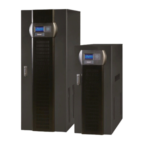
Tescom
Tescom DS200 Series User manual
Tescom
Tescom DS300 Series User manual
Tescom
Tescom DXA3000 Series User manual
Tescom
Tescom DS3250A User manual
Tescom
Tescom XA-200P Series User manual
Tescom
Tescom NEOLINE 6-20KVA UPS User manual
Tescom
Tescom CL110DR User manual
Tescom
Tescom AVR 11 User manual
Tescom
Tescom DS3200H User manual
Tescom
Tescom TEOS 400E-EB PRO User manual
Tescom
Tescom XA206P User manual
Tescom
Tescom DS300B Series User manual
Tescom
Tescom DX3000-U1 Series User manual
Tescom
Tescom DS300T Series User manual
Tescom
Tescom T3100P User manual
Tescom
Tescom DS360H User manual
