CertaUPS C300R-020-B User manual

1
C300R 1-3 kVA
Rack/Tower
1000-3000VA
Installation/Manual

2
IMPORTANT SAFETY INSTRUCTIONS
SAVE THESE INSTRUCTIONS
This manual contains important instructions for the
C300R 1000-3000VA series that should be followed
during the installation and maintenance of the UPS and
batteries. Please read all safety and operating
instructions before operating the UPS. Adhere to all
warnings on the unit and those contained within this
manual. Please also follow all operating and user
instructions provided.

3
1. Introduction..........................................................................................................................................................4
2. Safety Warning .....................................................................................................................................................6
2.1 Description of Commonly Used Symbols.......................................................................................................8
3. Installation............................................................................................................................................................8
3.1 Inspection of Unit..........................................................................................................................................8
3.2 Unpacking the UPS........................................................................................................................................9
3.3 UPS Setup......................................................................................................................................................9
3.4 EBM Installation (Optional) .........................................................................................................................16
3.5 UPS Initial Start up ......................................................................................................................................24
4.1 Display Panel ...............................................................................................................................................25
4.2 Operating Mode..........................................................................................................................................30
4.3 Configuring Load Segment ..........................................................................................................................31
4.4 Configuring UPS for EBM Numbers .............................................................................................................32
4.5 Configuring Green Function ........................................................................................................................33
5. Communication Port...........................................................................................................................................34
5.1 RS-232 and USB Communication Ports .......................................................................................................34
5.2 Emergency Power Off (EPO)........................................................................................................................35
5.3 Network Management Card (Optional).......................................................................................................36
6. UPS Maintenance ...............................................................................................................................................36
6.1 UPS and Battery Care ..................................................................................................................................36
6.2 Storing the UPS and Batteries .....................................................................................................................36
6.3 Time to Replace the Batteries .....................................................................................................................38
6.4 Replacing the UPS Internal Batteries...........................................................................................................39
6.5 Testing New Batteries .................................................................................................................................43
6.6 Recycling the Used Battery..........................................................................................................................44
7. Specification .......................................................................................................................................................45
7.1 Specification................................................................................................................................................45
7.2 Rear Panels..................................................................................................................................................48
8. Trouble Shooting...........................................................................................................................................50
8.1 Audible Alarm Trouble Shooting .................................................................................................................50
8.2 General Trouble Shooting ...........................................................................................................................51
9. Software Installation...........................................................................................................................................52

4
1. Introduction
The C300R is a compact, Line Interactive, pure sinewave UPS. The C300R is designed
to support critical equipment such as desktop PCs, servers, workstations and other
networking equipment. The C300R is available with an output rating of 1000-3000VA.
The C300R protects connected equipment from power issues including power sags,
spikes, brownouts, line noise and blackouts.
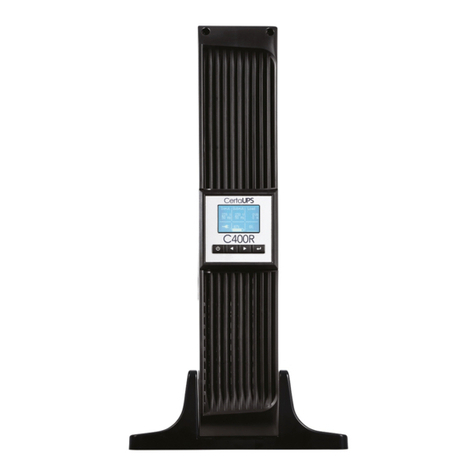
The C300R can either be rack mounted or
configured as a free standing Tower. The front
panel of the UPS includes an LCD display with
four control buttons that allow the user to
monitor, configure and control the unit. On the
LCD, a graphical bar, two status indicators and
four alarm indicators are included. See image:
A control button from the front panel allows the user to turn off the AC fail alarm and
initiate the UPS self-test sequence. The UPS case is made of metal. This UPS is
powered from the AC mains and supplies an AC output via the C13/C19 ports on the
rear of the UPS. Communication and control of the UPS is available through serial or
USB ports located on the rear panel. The serial port will support communications
directly to a server.

5
Features:
Cold start capabilities.
Selectable input and output ranges.
Easy battery replacement design.
Ability to extend runtime with scalable external battery module
(EBM).
Built-in boost and buck Automatic Voltage Regulator (AVR).
Built-in Dry contact/RS-232/USB communication ports.
Microprocessor control guarantees high reliability.
High frequency design.
SNMP allows for web-based, remote or monitoring management.
(Optional) Overload, short-circuit, and overheat protection.
Rack/Tower 2 in 1 Design.
19”rackmount available for all models.

6
2. Safety Warning
DANGER:
This UPS contains high voltages. All repairs and servicing should be performed
by trained service personnel only. There are no user serviceable parts inside
the UPS.
WARNING:
This UPS contains its own energy source (batteries).The UPS output may
carry live voltage even when the UPS is not connected to an AC supply.
To reduce the risk of fire or electric shock install this UPS in a
temperature and humidity controlled indoor environment, free of
conductive contaminants.(Ambient: 0-40°C)
To reduce the risk of fire, please connect to a circuit breaker rated at
20A.
To comply with international standards and wiring regulations the total
leakage current of the UPS and the connected loads must not exceed
3.5mA.
The electrical supply that feeds the UPS shall be installed near the UPS
and shall be easily accessible.
Disconnection of an earth line should be made at the point that is
furthest away from the UPS in order to maintain the dedicated earth line.
The UPS and Extra Battery Modules (EBMs) should be connected closely
together to ensure that the interconnecting wires cannot be touched.

7
CAUTION:
Batteries can present a risk of electrical shock or burns from high short-
circuit current. Observe proper precautions. Servicing should only be
performed by qualified service personnel who have knowledge of
batteries and the required precautions. Keep untrained personnel away
from the batteries.
The safe disposal of batteries is required. Refer to your local
environmental regulations e.g. WEEE Regulations for disposal
requirements.
Never dispose of batteries in a fire. Batteries may explode when exposed
to flames.
The following block diagram shows the basic internal circuit configuration of the UPS.

8
2.1 Description of Commonly Used Symbols
Some or all of the following symbols may be used in this manual and
therefore, all users should familiarise themselves with their definitions.
Table1. Description of Commonly Used Symbols
3. Installation
3.1 Inspection of unit
Visually inspect the UPS for damage upon receipt. If the internal packaging
or UPS has been damaged during shipment, keep the box and packaging
materials in their original form, notify the carrier and contact the supplier
immediately.

9
3.2 Unpacking the UPS
To unpack the system:
1. Open the outer box and remove the accessories packaged with the UPS.
2. Carefully lift the UPS out of the outer box and set it on a flat, stable surface.
3. Discard or recycle the packaging in a responsible manner, or store it for future
use.
3.3 UPS setup
All models in the C300R range are designed for tower or rack orientation.
Please follow the instructions on the next few pages that relate to the
configuration that’s best for your system.
Tower
The C300R can be placed either horizontally or vertically. An optional stand
is included with this UPS in order to allow for tower configuration. The
stand can be used in order to position the UPS in an upright position. In
order to achieve this, the UPS stand should be attached to the bottom of
the tower. Please use the following instructions in order to install the UPS
within the UPS stand:

10
1. Carefully place the UPS within the stands.
2. Slide the UPS stands to each end of the tower.

11

12
2. Pull out the LCD panel and rotate it in a
clockwise direction to 90 degrees and then push it back into the front
panel. (The LCD is on a short wire please take care when executing this
step).

13
Rackmount setup
The UPS can also be installed within a 19”rack cabinet. The UPS takes up 2U
of rack space for each additional EBM installed an additional 2U rack space is
required.
Use the following procedure to install the UPS within a rack cabinet.
1. Align the mounting ears with the screw holes on the side of the UPS, and
tighten the screws.
2. Assemble the rack rails with the rackmounting.

14
3. Slide the UPS into the rack rails and lock it into the rack enclosure.
4. Tighten the screws. The UPS is now ready for cabling unless you are installing
EBMs.

15

16
3.4 EBM Installation (Optional)
Connecting the EBM in Tower form:
1. Position the UPS and EBM within the extended UPS stands then slide the
stands to either end of the tower.
2. Tighten the screws on the UPS cover for stabilisation.
3. Connect an Earth line from the UPS (port A) to the EBM (port B)

17
4. Take off the front panel. To do this remove
the 2 top screws from the front of the UPS and carefully take out the LCD
screen and remove the screw that is behind it. Finally push inward the small
blanking plate on the side of the front panel in order to remove it. This then
enables you to connect battery terminal (A) from the UPS to the EBM terminal
(B) shown below. After doing this reassemble the front panel.
5. After setting up the UPS the load can then be connected. Please make
sure the load equipment is turned off before connecting all loads into
the output C13/C19 ports.

18
Connecting the EBM in a rack form
1. Using the same method as assembling the UPS in rack form, assemble the
EBM into the rackmounting above or below the UPS.

19
3. Take off the LCD box, and unscrew the internal
screws.
4. Take off the front panel. To do this remove the 2 top screws from the
front of the UPS and carefully take out the LCD screen and remove the
screw. Finally push inward the small blanking plate on the side of the
front panel in order to remove it. This then enables you to connect the
battery terminal (A) from the UPS to the EBM terminal (B) shown below.
After doing this reassemble the front panel.

20
5. After installing the UPS into the rack the load
can then be connected to the UPS. Please make sure the load equipment
is turned off before connecting all loads into the output C13/C19 ports.
This manual suits for next models
1
Table of contents
Other CertaUPS UPS manuals

CertaUPS
CertaUPS Tower 6-10K User manual

CertaUPS
CertaUPS C200 Series User manual

CertaUPS
CertaUPS C300R User manual

CertaUPS
CertaUPS C200-1500 User manual

CertaUPS
CertaUPS C650 User manual

CertaUPS
CertaUPS PowerControl C500R-060-B UPS User manual

CertaUPS
CertaUPS C400 Series User manual

CertaUPS
CertaUPS C400R Series User manual

CertaUPS
CertaUPS C500 User manual

CertaUPS
CertaUPS C60 Series User manual