Teseq NSG 435 User manual
1
NSG 435 ESD SIMULATOR
USER MANUAL
601-131H

NSG 435 ESD simulator
NSG 435 ESD SIMULATOR
USER MANUAL

1 General 5
1.1 Explanation of the symbols used in this manual 5
1.2 Safety 6
2 Introduction 8
2.1 Electrostatic discharge (ESD) 8
2.2 Simulation 9
2.3 Effects on the EUT 11
3 NSG 435 12
3.1 System descritpion 12
3.2 The simulator 13
3.2.1 Function modules 13
3.2.2 Block diagram 14
3.2.3 Operating elements 15
3.3 System components 17
3.3.1 Basic set 17
3.3.2 Charging unit/battery-pack 17
3.3.3 Options 19
3.3.4 Mains power supply unit 19
3.3.5 Discharge networks 20
3.3.6 Remote triggering 21
3.3.7 Measurement adapters 22
4 Commissioning 23
4.1 Inspection 23
4.1.1 Function check 23
5 Operation 25
5.1 General 25
5.2 Switching on 25
5.3 Battery monitor 27
CONTENTS

5.4 Air/Contact-discharge 28
5.5 Voltage 29
5.6 Polarity 30
5.7 Repetition frequency 31
5.8 Counter 31
5.9 Preselect counter 32
5.10 Automatic polarity switching 34
5.11 Continuous operation 37
5.12 Storing voltage settings 39
6 Test procedures 41
6.1 Standard-conforms procedures 41
6.2 Other conditions 41
7 Vericationofthepulsedata 43
8 Maintenance 44
8.1 Servicing 44
8.2 Calibration 44
8.3 Exchanging the R/C network 47
8.3.1 Derating of pulse repetition at increased capacitance 49
8.4 Repairs 50
8.5 Disposal 50
9 DeclarationofConformityCE 51
10 Technicalspecications 52
11 ESD standards 54
12 Warranty 55
13 Oderinginformation 56
14 Addresses 57
5
1.1Explanationofthesymbolsusedinthismanual
Please take note of the following explanations of the symbols used in order
to achieve the optimum benet from this manual and to ensure safety during
operation of the equipment.
The following symbol draws your attention to a circumstance where non-
observation of the warning could lead to inconvenience or impairment in the
performance.
Example:
1 GENERAL
Thisconnectionmustnotbeconfusedwiththemains
powerinput.
The following symbol draws your attention to a circumstance where non-
observation of the warning could lead to component damage or danger to the
operating personnel.
Example:
Neverconnectordisconnectthepistolwhilesystemis
performingatest.
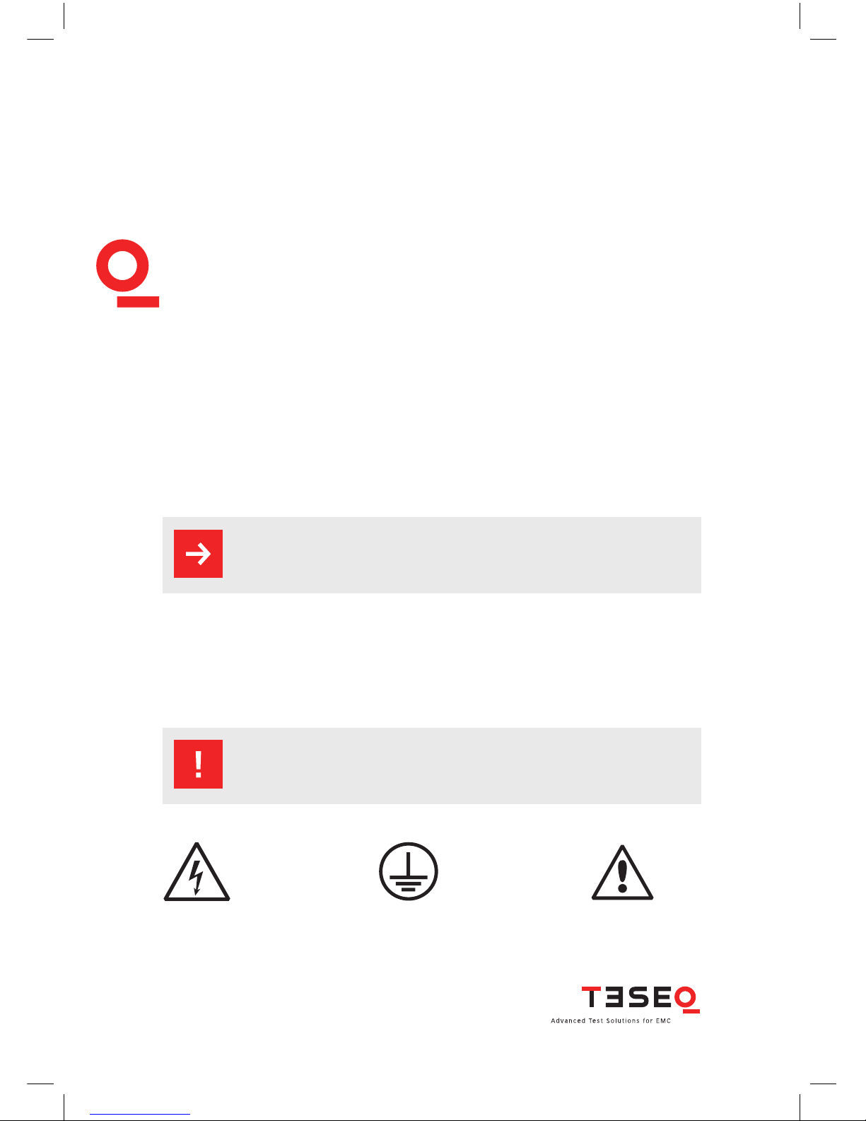
Symbols used on the product:
Danger
highvoltage
Protective
earthterminal
Attention
refertomanual
6
NSG 435 ESD simulator
1.2Safety
Onlytrainedpersonnelmayoperatetheinstrument.
Thisitemofequipment,togetherwithitsaccessories,
worksathighvoltagesofupto16.5kV.Anycareless
handlingornon-observanceoftheoperatinginstruc-
tionscanhavedangerousconsequences.
The NSG 435 simulator is not a toy! It is a professional tool and belongs only in
the hands of specialists and appropriately trained personnel.
When powered by its own batteries the simulator can be active even without
any power cable being connected.
The instrument must not be switched on unless a correctly connected earth or
ground cable (pulse current return path) is in place. The original earth cable supplied
with the instrument is to be used. Any replacement cables must be fabricated in
such a way that they cannot be accidentally connected to a mains outlet socket.
Do not touch the test nger! There is a danger of an unpleasant electric shock
if the instrument is switched on (LC-display active).
Personnel tted with a heart-pacemaker must not
operatetheinstrumentnorapproachthetestrigwhile
it is in operation.
These operating instructions form an integral part of the instrument and must
be available to the operating personnel at all times.
The instrument must not be used for any purpose other than testing the ESD
immunity of electronic equipment.

7The construction of the simulator is not designed for use in an explosive env-
ironment.
Eachelectrostaticdischargeproducespowerfulelectro-
magneticinterference.
Nearby electronic equipment can be seriously disrupted unless
the appropriate counter-measures are taken. Perform ESD tests
preferably in a shielded room.
The rechargeable batteries in the handgrip must not be short-circuited under
any circumstances. They must only be recharged with the original charging unit
supplied with the simulator. Should they have to be replaced, kindly observe
the relevant recommendations for the disposal of nickelmetal hybrid batteries
(if delivered before 2002).
The instrument must not be opened. Repairs, maintenance work and internal
adjustments are only to be carried out by a qualied service engineer.
Use the instrument only in dry surroundings. Any condensation that occurs
must be allowed to evaporate before putting the simulator into operation.
Long periods of exposure to sunlight and excessive warming by external energy
sources are to be avoided.
Do not continue to use the instrument should any mechanical damage occur.
The instruments housing has both an insulating and a screening function which
can only be assured while the housing is intact. Return a damaged simulator to
a Teseq service centre immediately for repair.
Teseq AG Luterbach, Switzerland and the associated sales organizations accept
no responsibility for personal or material damage nor for any consequential
damage that may result from irresponsible operation of this instrument.

8
NSG 435 ESD simulator
2.1Electrostaticdischarge(ESD)
Under appropriate ambient conditions, both material objects and even the
human body itself can become charged with electrical energy. This effect is
due to «electrostatics», a phenomenon that has been known since the earliest
times. Thales von Milet (600 BC) noticed how amber attracted very light particles
when it was rubbed. Touching a charged item against a conductive object leads
to a charge equalization through a spark discharge which produces a brief but
powerful electromagnetic eld.
This effect can be explained as follow: Two insulating substances with differing
dielectric constants become charged when rubbed together, i.e. one material
gives electrons to the other one. This effect is known as electrostatic charging.
The same can happen to a person. When somebody walks around in a dry
atmosphere on a carpet with good insulating properties, a charge of several
thousand volts can be built up. If, now, that person comes close to a conductive
surface, the charge that he or she is carrying ows away through a hefty spark
discharge.
The high equalizing current that ows, and the associated large electromagnetic
eld that hence results, can cause electronic devices (computers, terminals,
process controllers, vehicle electronics, solid state devices, credit or memory
cards, etc.) to malfunction or even be destroyed.
2 INTRODUCTION

92.2 Simulation
A systematic investigation of electronic equipment and installations to deter-
mine their electromagnetic compatibility (EMC) is, today, a necessity if one is
not prepared to suffer the economic disadvantages that could otherwise ensue.
As a logical consequence, appropriate testing is now a legal requirement for
the sale of electronic products within the EC.
The ESD test plays an important role in the range of interference sensitivity
tests. It simulates frequently occurring effects and guides the development
engineer to any weak spots in an instrument or item of equipment through a
combination of high voltage and high frequency properties.
A simulation device must be constructed so that it reproduces practical con-
ditions realistically. Furthermore, the results obtained (interference sensitivity
threshold) must be reproducible.
The interference immunity of an instrument is not only dependent on its con-
struction, it is also largely dependent on the quality or the consistency of the
mass production techniques used. Knowing this has led to the demand for
individual testing or at least random sample testing.
Further weak spots, which could affect the overall interference immunity, can
arise through the assembly of instruments into complete systems because
of the installation method used, the cabling and the earthing. An ESD check
on systems is therefore also prescribed. Such tests provide valuable informa-
tion about the immunity of the system to effects that occur only sporadically
under operating conditions and hence represent difcult to detect sources of
disruption.
10
NSG 435 ESD simulator
The ESD simulator NSG 435 fulls the requirements of various applications in
an ideal manner:
Ergonomic shape For nontiring use
Operation Operating elements and display always in view
of the user. Constant check on the test values.
Battery-powered Independence from a mains power feed.
Compact and handheld No bench unit as the high voltage source,
no high voltage cable. Optimal freedom of
movement around the device or system
to be tested.
Carrying case Simulator and accessories can be handily
packed and conveniently transported.
Microprocessor-control All the functions are «on-board», including a pre-
settable counter, pre-programmed test values,
discharge voltage measurement, etc.
Precision The test parameters are maintained precisely
for reliably reproducible tests.
Flexibility The specications prescribed in the standards
are more than fullled in every respect. The
instrument also offers many additional handy
features.
Safety The high voltage simulator is automatically de-
activated if the instrument remains unused for a
period of time.
Longterm operation Automatic longterm operation for stationary
applications with mounting on a tripod.
Application eld Development optimization, type approval, EMC
certication, batch testing (individually), testing
of fully installed systems.
112.3EffectsontheEUT
The most signicant interference components of an electrostatic discharge
are of a high frequency nature. The interference paths and effects have to be
assessed in the range from about 30 MHz to the multi-GHz range.
The extremely rapid rise time of a discharge affects an object under test mostly
through:
magnetic HF-coupling between electrical conductors in the electronics and
the discharge current path.
electrical coupling between the discharge current and signal lines. A dis-
charge current to the EUT ows proportionally through all the associated-
conductors (earth, mains, data lines, screening, etc.) according to their rela-
tive impedance.
Malfunctions in insufciently immune electronic equipment and systems make
themselves apparent through:
program crashes
blocking of command sequences
incorrect commands, statuses or data being processed
partial system resets (e.g. only in peripheral modules which lead to
errors that the system does not recognize)
disturbance or destruction of interface chips
destruction of insufciently protected MOS or other components
ESD testing usually shows up all the weak spots in the HF-range of a piece of
equipment simultaneously. The uses to which the NSG 435 simulator can be put
hence go way beyond those called for in standard-conform applications.
This instrument provides the engineer with a means to detect sources of error
caused by unsuitable earthing, poor ground connections, insulation problems,
etc.
The simulator also serves as a reliable aid for localizing hidden wiring faults
during acceptance trials on installations.
Use can also be made of the instrument as an insulation tester to determine
the breakdown voltage of switches, relay contacts, insulators, etc.

12
NSG 435 ESD simulator
3.1Systemdescription
By using the latest materials, construction methods and manufacturing tech-
niques for the robust housing shell, together with highly insulated modules, the
newest high voltage technology and a control unit built using the SMD-tech-
nique, it has been possible to integrate all the functions that a comprehensive
simulator system should offer into one compact instrument.
Professional industrial designers have ensured an optimized ergonomic concept.
The instrument, with its well-balanced handgrip, sits comfortably in the users
hand and guarantees non-tiring operation. Both the operating elements and the
display window remain in view of the user while work is in progress.
Thanks to its battery pack, the NSG 435 offers optimal freedom of movement
around the workplace and is an ideal test instrument not just for the deve-
lopment engineer but also for quality control purposes, system tests and for
investigations in the eld.
As supplied in the basic set, the system is equipped with a 150 pF/330 Ω
discharge network for the IEC/EN 61000-4-2 standard. The discharge voltage
of up to 16.5 kV for air-discharges and up to 9 kV for contact discharges ensure a
comfortable test margin over and above the levels called for in the standard.
The instrument is well equipped to cope with other (and future) standards. The
accessories include various networks and test ngers that can be attached by
the user himself.
The basic set contains everything necessary for general use. For special tasks
a rich assortment of accessories is available such as a mains power unit for
longterm operation, a remote triggering unit via an optical link, spare battery-
packs, discharge networks, test ngers, etc.
3 NSG 435

133.2Thesimulator
3.2.1 Function modules
The NSG 435 simulator is modularly constructed from a number of function
units that are all housed in a multi-part, molded shell.
HV-generator
discharge network
(exchangeable)
measuring electronics
high voltage relay
polarity changeover
Control section µ-processor,
keypad, display and remote
trigger connection
Test nger
(exchangeable)
Earth cable
connection
Pulse
trigger
Exchangeable
battery pack
Tripod bush
UNC1/4-20
Handgrip
14
NSG 435 ESD simulator
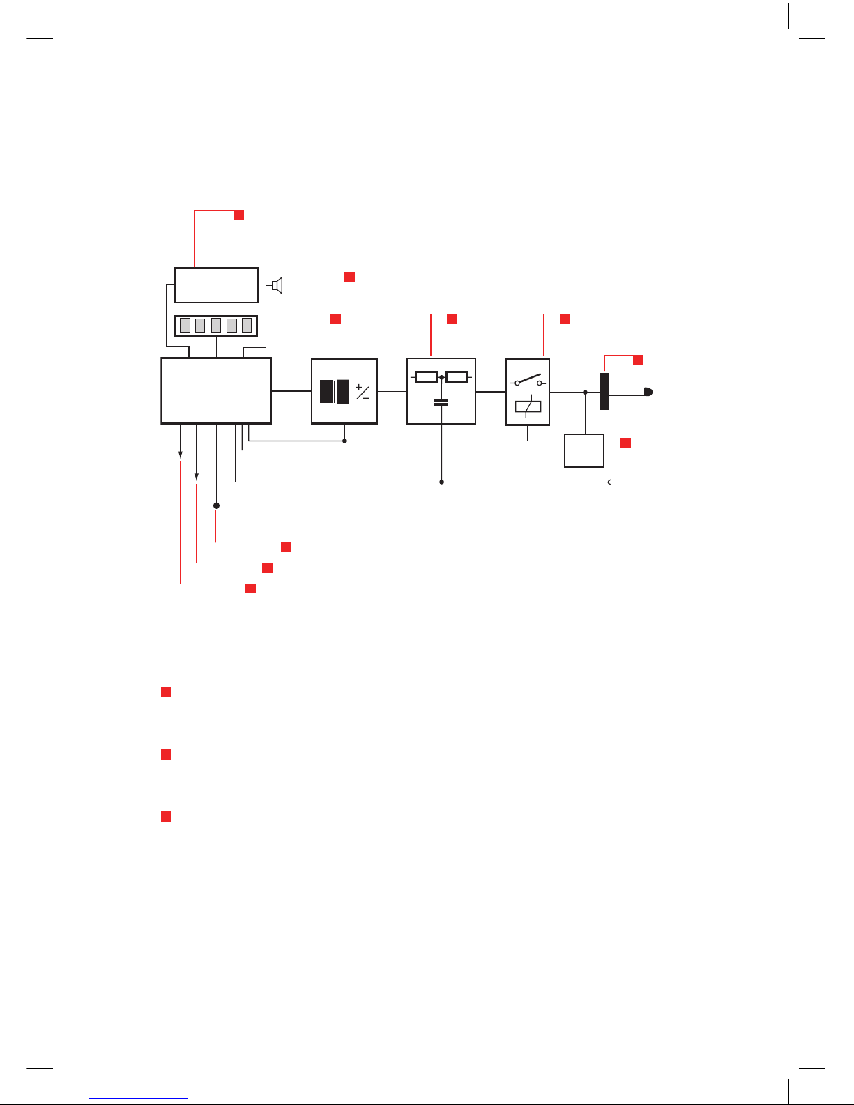
3.2.2Blockdiagram
The function units are shown in the block diagram:
The microprocessor controls and monitors all the generator functions:
Keypad entries are checked for plausibility. Unacceptable entries are rejected
and an acoustic warning noties the user of the error.
Values entered are clearly shown on the large display screen. Further infor-
mation shows the operating status and the counter settings.
The battery charge state is continuously monitored. A tendency towards low
voltage is shown on the display. The instrument’s functions are inhibited
once the battery voltage is insufcient to guarantee the pulse parameters.
High voltage
generator
Test
fingerµP Control unit
±10.0kv Buzzer
Display
Trigger button
Ext. trigger
Batt / Mains PSU
Discharge
network
High voltage
relay
Measurement
circuit
15
The high voltage generation is dynamically controlled by the processor.
Varying load conditions, supply voltages, etc. can thus be taken into account
and have no effect on the pulse parameters.
The instrument switches itself off automatically if it is not used for a while.
The pulse parameters and operating mode remain stored and ready for use
once the simulator is switched on again.
The charge voltage to the network is kept constant as long as the trigger is
active. The high voltage is discharged internally when the trigger is reset.
If no discharge occurs when set for an air-discharge and the trigger is active,
the processor waits for about 15 s then autonomously resets the trigger
and discharges the network internally. An acoustic warning is also sounded.
A measurement facility at the pulse output measures the actual air-voltage
reached during an air-discharge and shows the result on the display.
Pulse triggering is monitored. Once an arc has occurred the network is
discharged internally so that no further arcing is possible.
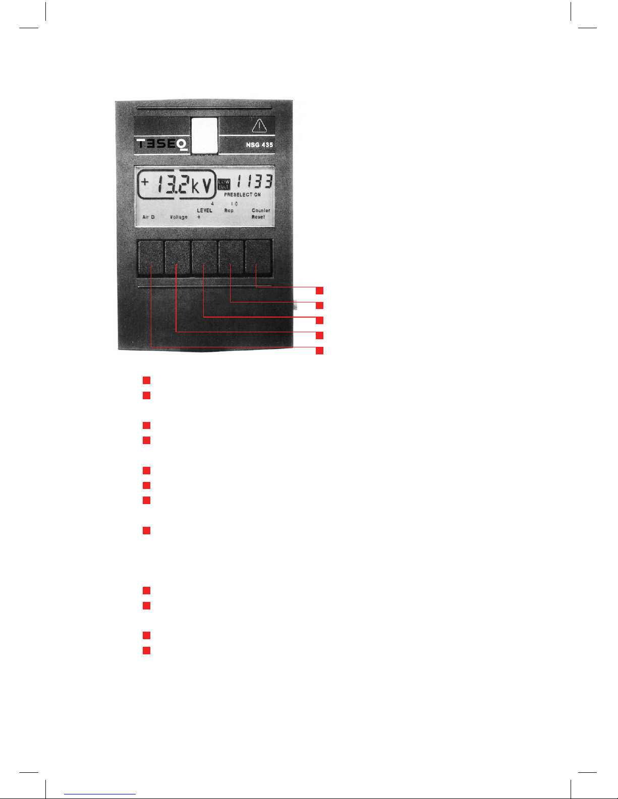
3.2.3 Operating elements
Apart from the trigger button itself (pulse triggering) all the operating elements
are on the surface of the instrument that faces the operator.
The NSG 435 is switched on/off with the main switch.
The signicance of the elements in the display eld can be seen in the following
picture. Further information can be found in section 5 «Operation».
Operation of the whole instrument is effected via the ve multifunction buttons
(soft-keys). These buttons perform different functions depending on the stage
of operation. The current function is shown on the display in each case.
The designation F1 to F5 used for these buttons in the following notes serve to
simplify the descriptions in this manual.
16
NSG 435 ESD simulator
F1 Toggle between air and contact-discharge (and vice versa)
Increment voltage and counter
F2 Activation of voltage setting
Decrement voltage and counter
F3 Polarity switching:
Selection of pre-programmed test levels
Preselect counter on/off
F4 Selection of discharge mode:
Single discharge Repetitive discharge at 0.5, 1, 5, 10, 20, 25 Hz
for air-discharge
Repetitive discharge at 0.5, 1, 5, 10 Hz for contact-discharge
Automatic polarity switching
Storage of programmed test levels
F5 Resets the counter
Return from second function
F1
F2
F3
F4
F5
17The trigger button in the hand-grip works as folIows, depending on the
operating mode selected:
For single discharge as a pulse button
(1 pulse when pressed)
For repetitive discharges as on/off button
(discharge while the button is pressed)
For repetitive discharges with as a holding on/off button
preselect counter active (switch on by pressing the button,
switch off by pressing the button again)
The remote triggering facility is a substitute for the manual trigger button by
producing the relevant control signals.
3.3Systemcomponents
3.3.1 Basic set
The basic set is packed in a practical carrying case and comprises:
Carrying case 42 x 32 x 13.5 cm (16.5 x 12.5 x 5.5 ” approx.)
ESD simulator NSG 435 with battery-pack and 150 pF/330 Ω discharge network
conforming to IEC/EN 61000-4-2, Ed. 1.2:2001
One test nger each for air- and contact-discharges
Earth cable
Battery charger
Operating instructions
Calibration certicate
This set contains all the items necessary under normal conditions to perform
tests conforming to IEC/EN 61000-4-2, Ed. 1.2:2001.
18
NSG 435 ESD simulator
3.3.2Chargingunit/battery-pack
The battery charger supplied in the set is designed for multi-country use and
is coming with various mains adaptors. Green LED shows fully charged battery
status.
Operation range 100 V to 240 V (50/60 Hz)
Charging of the battery takes about 1 hour. For further details please refer to
separate manual.
The battery has to be removed from the NSG 435 for charging via the jack con-
nector. One charge is sufcient for several days of normal test operation.
Battery life expectancy:
Ambient temperatures over 50°C can lead to degradation of the battery. If
treated carefully, more than 300 charge/discharge cycles can be expected
without any noticeable reduction in capacity.
The charger and battery-pack form a matched entity. The battery must not be
charged from any other unit and the charger is to be used exclusively for the
intended purpose.
Operating advice:
Avoid short-circuits. Keep the contacts clean
Use the equipment only in dry surroundings
Do not switch the mains off while charging otherwise the timer will be
restarted
Never leave the battery in a fully discharged state for a long time
Do not attempt to recharge a full battery
Recharge the battery about every 6 months even if the instrument is not
being used

19
The handgrip adapter is an integral part of this power supply unit. It contains
electrical components that are necessary for this mode of operation. It is not per-
missible to operate the NSG 435 with a power supply unit from another system.
The power supply unit can be used on all common AC mains supplies without
having to make any adjustments, thus:
80 to 240 V (50/60 Hz) with 3-pin IEC connector
Matching 3-core mains cable
3.3.3 Options
A range of additional accessories is available for special applications and for
testing to other standards:
Spare battery-pack (space available in carrying case)
Mains power supply with adapter
Remote triggering unit with 5 m (197 ”) optical cable
Discharge networks and test ngers for other standards
Coaxial measurement adapter (target)
3.3.4Mainspowersupplyunit
Instead of using the normal battery-pack, a mains power supply unit type
INA 402 can be used for stationary applications and for longterm test pur-
poses.

20
NSG 435 ESD simulator
The power supply unit must be connected to a mains outlet having a protective
earth.
The protective earth connection does not replace the earth cable for the opera-
tion of the NSG 435. To ensure safe and valid test operation the earth cable must
be correctly connected as the pulse return path in every case.
The mains power supply unit is constructed in conformity with the relevant
safety standards and carries the appropriate test symbol.
3.3.5Dischargenetworks
The basic set contains a discharge network and test ngers that conforms to
IEC/EN 61000-4-2, Ed. 1.2:2001.
Alternative networks can be installed for testing in accordance with other
standards.
The discharge network and test ngers form a mutually matched combination.
They are labeled with a corresponding INA number. The specied pulse data
are only achieved while this combination is maintained.
Several combinations are given in the order list. The C and R values of the
discharge network can also be specied for other applications.
Networks conforming to other standards can be built upon request. The speci-
cations of the standard must be fully dened.
Exchanging the discharge network is described in section «Exchanging the R/C
network».
Table of contents
Other Teseq Test Equipment manuals


Popular Test Equipment manuals by other brands


Apera Instruments
Apera Instruments GroStar GS2 user manual

Agilent Technologies
Agilent Technologies Medalist i3070 Series System installation

Mictel LLC
Mictel LLC ECCT instruction manual

Viavi
Viavi Seeker X with MCA III installation guide

Kane
Kane KANE-VCT instruction manual

GemOro
GemOro AuRACLE Quick operation guide

Image Engineering
Image Engineering LE7 x2 user manual

Gossen MetraWatt
Gossen MetraWatt SECUTEST BASE operating instructions

Rigol
Rigol DS2000A Series Specifications

ROD-L
ROD-L M25 quick start guide

Granite Digital
Granite Digital Save A Battery 1295 Instruction & Diagnostic Manual

Multi
Multi MET-2 instruction manual