Kane KANE-VCT User manual

EN
61010-1
CAT IV
600V
Instruction Manual
KANE-VCT
Voltage &
Continuity Tester
Voltage Indication
12 - 690V AC/DC with Continuity
Inventory No: MAN00160
Rev.: 1.0221
February 2021

Certicate of conformity
As the manufacturer of the instrument listed
below, we declare under our sole responsibility
that the product:
KANE-VCT
to which this declaration relates is in conformity
with the relevant clauses of the following
standards:
EN 61010-1:2010
EN 61010-2-030:2010
EN 61010-031:2015
EN 61243-3:2014
EN 61326-1
IEC 60529 (IP65)
LVD & EMC
The safety & performance of this instrument is
assured when operated within the specications
in this instruction manual.
The product identied above conforms to the
requirements of council directive 2014/35/EU
Contents
I. Overview 3
II. Safety Notice 3/4
III. Instrument Symbols 5/6
IV. Technical Specication 6
V. Display & Controls 7
1. Operating Instructions 7
2. AC Voltage Indication 8
3. DC Voltage Indication 9
4. Single Pole Voltage Indication 10
5. Continuity 11
6. Phase Sequencing Indication 11/12
7. Maintenance 13
8. Battery Replacement 13
9. Calibration 13
10. Accessories 14
11. Warranty Information 14
1 2

I. Overview
Thank you for purchasing a KANE-VCT voltage
continuity tester. This tester has been designed
in accordance with the latest international safety
standards.
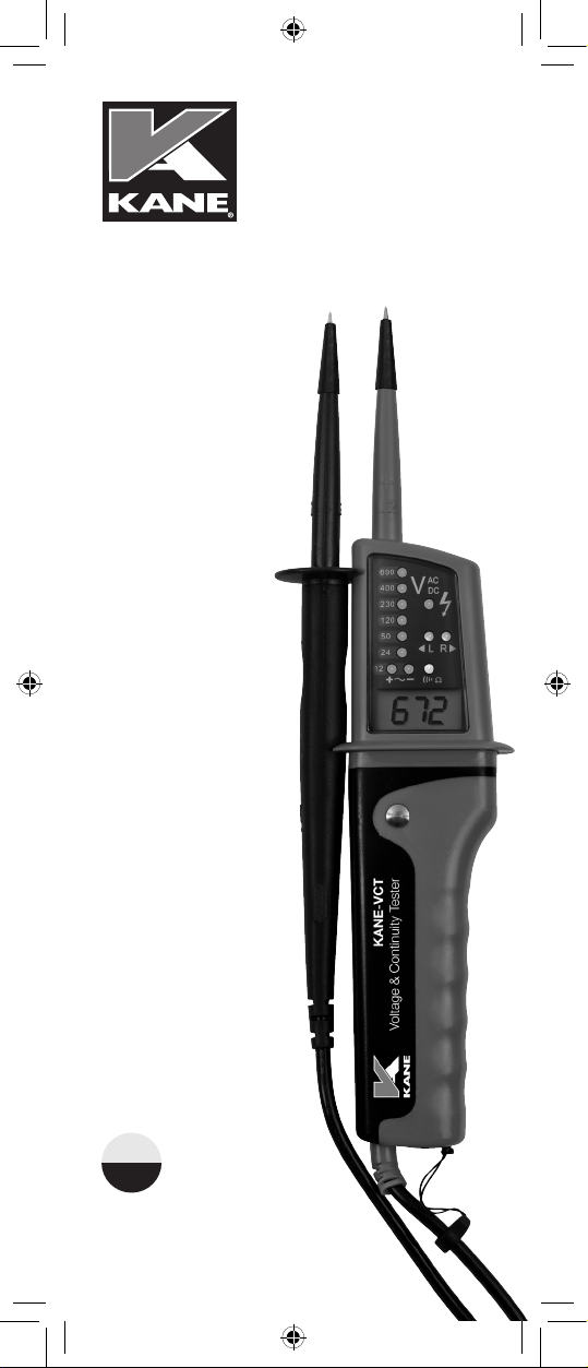
The KANE-VCT is a fully automatic voltage indicator
capable of measuring AC/DC voltage up to 690V.
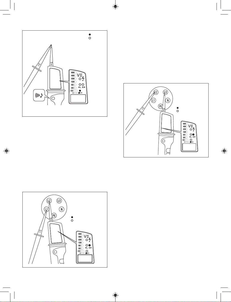
The KANE-VCT has visual & acoustic continuity
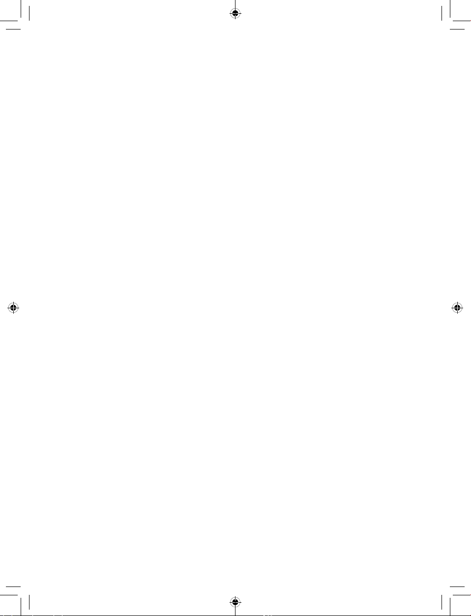
indication, single pole detection & a phase rotation
sequencing indication.
Constructed in accordance with IEC 61010-1 & IEC
61243-3.
• Single pole phase indication
• 2 pole phase rotation indication
• LED & LCD display
3 4
II. Safety Notices
This instruction manual contains information that
must be followed for operating the meter safely &
maintaining the meter in a safe operating condition. If
this meter is not used in the manner that is specied,
the protection provided may be impaired.
Warning! Warns of potential danger, refer to
the instruction manual to avoid personal injury
or damage to the meter.
Caution! Dangerous voltage. Danger of
electrical shock.
Perfect display is only guaranteed within a
temperature range of -10 - 50°C, relative
humidity <85%.
A statement about protection impairment
if used in a manner not specied by the
manufacturer.
The voltage indicators are designed to be used by
skilled persons & in accordance with safe methods
of work.
The voltages marked on the voltage indicator are
nominal voltages and the voltage indicator is only to
be used on installations with the specied nominal
voltages.
The dierent indicating signals of the voltage
indicator are not to be used for measuring purposes.
Before using a voltage indicator at locations with a
high background noise level, it has to be determined
whether the audible signal is perceptible.
II. Safety Notices (continued)
It is important to check the state of the battery before
use & to replace it if necessary.
The meter has been designed in accordance
with the safety regulations for electronic
measuring instruments, EN 61010-1:2010, EN
61010-2-030:2010, EN 61010-031:2015, EN
61243-3:2014 & EN 61326-1
Voltages above 75V DC or 50V AC may constitute a
serious shock hazard.
Before using the meter, check for physical damage to
the casing, in particular around the cable strain relief.
If the case is damaged, do not use the meter.
Check the test probes for damaged insulation or
exposed metal.
Check the leads for continuity.
Do not apply more than the rated voltage, as marked
on the meter between the terminals or between any
terminal & ground.
Do not use or store the meter in an environment of
high temperature, humidity, fumes, vapour, gaseous,
inammable, & strong magnetic eld.
The performance & safety of the instrument and the
user may be compromised in such circumstances.
Disconnect circuit power & discharge all high voltage
capacitors before testing resistance, continuity &
diodes.
Remove the batteries if the meter is not in use for a
long period.
Constantly check the battery as it may have leaked.
A leaking battery will damage the meter.
The meter may only be opened by a qualied service
technician for calibration & repair.

Warning! Warns of potential danger, & to
comply with the instruction manual.
Caution! Dangerous voltage, potential risk
of electrical shock.
Equipment protected throughout by
double or reinforced insulation. Complies
with IEC 536, class II
Suitable for live working
CE Symbol of conformity conrms conformity
with relevant EU directives. The meter
complies with EMC directives (2004/ 1 08/
EC), the Low Voltage Directive (described
in the standard EN 61010·1, 61243·3.
The DL6780/90 meets the standard
(2012/19/EU) WEEE. This marking
indicates that this product should not be
disposed with other household wastes
throughout the EC. To prevent possible
harm to the environment or human health
from uncontrolled waste disposal, recycle
it responsibly to promote the sustainable
reuse of material resources. To return your
used device, please use the return &
collection systems or contact the retailer
where the product was purchased. They
can take this product for environmental safe
recycling.
The instruction manual contains
information & references, necessary for
safe operation & maintenance of the
instrument. Prior to using the instrument
the user is kindly requested to thoroughly
read the instruction manual & comply with
it in all sections.
III. Instrument Symbols (continued)
IV. KANE-VCT Specication
5 6
CAT IV Applicable to test & measuring
circuits connected at the source of
the building’s low-voltage MAINS
installation.
Failure to read the instruction manual or
to follow the warnings and references
contained herein can result in serious bodily
injury or instrument damage. The respective
accident prevention regulations established
by the professional associations are to be
strictly enforced at all times.
III. Instrument & Manual Symbols
Symbols displayed on the instrument & in the
instruction manual:
EN
61010-1
CAT IV
600V
KANE-VCT Voltage Indicator Specication
2 Pole Voltage Indication
Voltage range 12 - 690V AC/DC
LED Resolution 12, 24, 50, 120, 230, 400 & 690V
LCD Resolution 1 V ±
Voltage detection Automatic
Frequency range 0 - 400Hz
Peak current 3.5mA
Operation time 30 seconds
Acoustic AC/DC signal ✓
Auto power on >12V AC/DC
IP rating IP65
Single Pole Indication
Voltage range 100 - 690V AC
Frequency range 50 - 400Hz
Continuity
Acoustic & visual ✓
Measurement range 0 - 400kΩ
Phase Rotation Test
Voltage range 100 - 690V AC
Frequency 45 - 65Hz
Over Voltage Protection 690V AC/DC
Other Information
Dimensions 225mm x 70mm x 28mm
Weight (net) 210g
Power supply 2 x 1.5V (RO3) AAA (supplied)
EAN 5039046000533

1. Operating Instructions
Carrying out measurements
Perform a self-test of the unit. Connect the two
test probes L1 and L2 together. The continuity
LED (6) will be lit, & an audible tone should be
heard.
Before any test, check the unit on a known
voltage source or approved voltage proving unit.
If the unit is defective it should be put out of service
& returned to KANE for repair.
7
2. AC Voltage Indication
8
V. Display & Controls
1. Test Probe (-) L1
2. Test Probe (+) L2
3. LED’s for voltage indication
4. LED for single - pole test
5. Right & Left LED, phase rotation indication
6. LED for continuity
7. LCD for voltage display (only DL6790)
8. Contact electrode for double-pole test of
phase rotation & single-pole test
9. Torch button on the back
10. Positive LED
11. Negative LED
12. Battery Compartment
AC Voltage
LED on
LED off
Always hold the test probes by the handles
behind the nger guards. Observe all the safety
notices at all times.
An audible tone is present when an AC voltage &
a negative DC voltage are indicated.
The maximum switch on time is 30 seconds.
When this time has elapsed, you must wait 10
minutes before retesting.
Connect probes to the voltage source observing
the polarity of the test probes, L2 is the positive
probe, L1 is the negative probe.
For AC voltage the value is indicated on the
LEDs (3) & on the LCD display.
The + & - LEDs are illuminated & buzzer is
audible.

3. DC Voltage Indication
DC Voltage
For DC voltage measurement, connect probe
L2 to the positive terminal & L1 to the negative
terminal. The voltage is displayed on the LEDs
& the LCD display. The positive LED (10) is
illuminated. If the polarity is reversed the buzzer
will sound. The negative LED (11) will be
illuminated.
LED on
LED off
4. Single Pole Voltage Indication
Perform a function test prior to this test.
This unit can be used as a single pole voltage
indicator when the batteries are inserted.
The single pole test is intended only as a quick
check. The circuit must be checked again for the
presence of voltage using the two-pole method.
Connect test probe L2 to the voltage source and
keep nger on the contact electrode (8). If an
AC voltage above 100 V is present the LED (4) is
illuminated & the buzzer sounds.
The single pole test can be negatively aected
by unfavourable conditions such as electrostatic
eld, good insulation etc.
9 10

LED on
LED off
Note: The continuity test is only possible when
batteries are installed & in good condition
5. Continuity Test
The continuity test is only possible when
batteries are inserted & in good condition.
Ensure the circuit under test is not live.
Connect test probes L1 and L2 to the circuit. The
continuity LED (6) will illuminate & the buzzer will
sound.
The unit will indicate continuity below 400K ohm.
LED on
LED off
Correct Phase Sequence
Phase Rotation Test
Rotary Phase of
Three-Phase Mains
6. Phase Rotation Indication
Perform a function test prior to this test.
This unit can determine the phase rotation within
a three phase supply.
Connect test probe L2 to the supposed phase
2 & the test probe L1 to the supposed phase 1.
If the R LED illuminates the phases are in the
correct sequence 1 to 2.
Connect test probe L2 to the supposed phase 3
& test probe L1 to the supposed phase 2.
If the R LED illuminates the phases are in the
correct sequence 2 to 3.
Connect test probe L2 to the supposed phase
1 & the test probe L1 to the supposed phase 3.
If the R LED illuminates the phases are in the
correct sequence 3 to 1.
During phase rotation test touch the contact
electrode.
If the L LED illuminates, then the phase sequence
is anti-clockwise.
LED on
LED off
Incorrect Phase
Sequence
6. Phase Rotation Indication (continued)
11 12

7. Maintenance
Do not attempt to repair this unit . There are no
user serviceable items in this unit. Never attempt
to open the casing apart from the battery cover.
Do not use the instrument if there is any physical
damage to the case or test leads.
The outside of the unit can be cleaned with a
soft damp cloth only.
Do not use abrasive or chemical cleaning agents.
8. Battery Replacement
Turn the battery cover by 90 degrees anti
clockwise.
Remove the cover & take out spent batteries.
Replace with 2 o 1.5 V AAA (LR03) batteries,
checking the correct polarity.
Replace the battery cover & turn by 90⁰
clockwise.
Discharged batteries should be disposed of
responsibly & with compliance with current
recycling & disposal regulations.
The recommended calibration interval for the
KANE-VCT is 12 months.
9. Calibration
The KANE-VCT is warranted to be free from defects
in materials & workmanship for a period of one year
from the date of purchase. If within the warranty
period your instrument should become inoperative
from such defects, the unit will be repaired or
replaced at KANE’s discretion. This warranty covers
normal use & does not cover damage which occurs
in shipment or failure which results from alteration,
tampering, accident, misuse, abuse, neglect or
improper maintenance. Batteries & consequential
damage resulting from failed batteries are not covered
by warranty.
Any implied warranties, including but not limited
to implied warranties of merchantability & fitness
for a particular purpose, are limited to the express
warranty. KANE shall not be liable for loss of use of
the instrument or other incidental or consequential
damages, expenses, or economic loss, or for any
claim or claims for such damage, expenses or
economic loss.
A purchase receipt or other proof of original purchase
date will be required before warranty repairs will be
rendered. Instruments out of warranty will be repaired
(when repairable) for a service charge.
For more information on warranty & service, contact:
Kane International Ltd,
11 Bessemer Road, Welwyn Garden City,
Hertfordshire, AL7 1GF, UK
t: 01707 384810
www.kane.co.uk
13 14
10. Accessories
Spares & Optional Accessories
KANE-PU690V 690V Proving Unit for proving
voltage.
MSC00125 Combined carry pouch for
KANE-PU690v Proving Unit &
KANE-VCT Voltage & Continuity
Tester
11. 24 Month Warranty

KANE and the KANE logo (registered in the UK and
elsewhere) are trademarks of Kane Group Limited,
used under licence.
All other marks are trademarks of their respective
holders. © 2021 Kane International Limited
Table of contents
Other Kane Test Equipment manuals