Tesla BM 510 User manual

OSCILOGRAF
OSCILLOSCOPE
TESLA BM 510

OBSAH CONTENTS:
I. Popis pfistroje a prislusenstvi . . 3I. Description of Instrument
II. Technické û d a je .................................. 7and Accessories .... 3
III. Nâvod k obsluze.................................. 10 II. Specifications .... 7
IV. Zpûsoby mëreni .................................. 16 III. Attendance Instructions . . 10
V. Princip c in n o s ti
.................................. 21 IV. Methods of Measurement . 16
VI. Ü d r z b a ................................................... 24 V. Principle of Operation . . . 21
VII. Opravy ................................................... 28 VI. Maintenance .... 24
VIII. Rozpis elekirickÿcli soucâsti . . 31 VII. R e p a irs ........................................ 28
Montâzni sestavy VIII. List of Electrical Parts . 31
Schemata Assembly Illustrations
Diagrams
Vzhledem k rychlém u vÿvoji svëtové elektroniky mëni se obvody a pristupuji a zlepSuji se souëasti naSich pFistrojû.
Nëkdy, vinou tisku a po2adavkû expedice, se nâm nepodafi zanést tyto zmëny do tiStënÿch pfiruëek.
Zmëny se proto v pflpadë potfeby uvâdëjl n a zvlâStnlm listë.
Owing to the rapid development of e le ctron ics in the w orld, the circu its of our instrum ents are altered and com
ponents of new types or im proved design are employed.
Sometim es, due to printing term s or the requ irem ent of speedy shipping, it is impossible to include a description
of such alterations in the appropriate printed manual.
Therefore, if n ecessary, such a lteratio ns are given in a loose leaf.

TESLA BM 510
Obr. 1
O scilograf TESLA BM 510 TESLA BM 510 O scilloscope
Instrukcni kniżka Instructions Manual

■
■
'
■ :
■

I. POPIS PRÍSTROJE
A PRÍSLUSENSTVÍ
Vÿrobce: TESLA BRNO, n. p., Brno,
Purkyñova 99
Název: Oscilograf
Typ: BM 510
Vyrobní
císlo: ...................................................
Pouzití: Pro mëfeni opakovanÿch elektric-
kÿch prübëhü, pro impulsní techniku
I. DESCRIPTION OF INSTRUMENT
AND ACCESSORIES
Manufacturer: TESLA BRNO N. C., Brno,
Purkyfiova 99, Czechoslovakia
Oscilloscope
BM 510 „ . . ^
Designation:
Type:
Serial No.:
Application: Measurement of periodical
electrical effects in pulse
techniques
Základni vlastnosti pristroje: Basic Properties
Frekvencni rozsah Frequency
vertikfilniho range
zesilovafie 0 — 1,5 MHz of vertifical
amplifier: 0—1.5 MHz
Citlivost: 20 mV/dil Sensitivity: 20 mV per scale division
Frekvencni rozsah Frequency
horizontślniho range
zesilovace 0 — 1 MHz of horizontal
amplifier: 0—1 MHz
Citlivost: 20 mV/dil Sensitivity: 20 mV per scale division
Ćasovś zśkladna: 0,1 sec/dil —5 ¿¿sec/dii Time base: 0.1 sec per scale div.—5 ^sec
per scale div.
Napdjeni: 220 V/120 V, 50 — 60 Hz Power supply: 220 V/120 V, 50—60 Hz
Pracovni podminky: Operating Conditions
Pracovni teplota Ambient
okoli: + 5 °C a i + 40 °C temperature: + 5°C to +40 °C
Relative
Relativni vlhkost: 40 % az 80 % humidity: 40 % to 80 %
Atmospheric
Tlak vzduchu: 86 000 N/m2 pressure: 86,000 N/m2 to 106,000 N/m2
a l 106 000 N/m2 Supply
Napajeci napgti: 120/220 V voltage: 120/220 V
Napśjeci kmitocet: 50 — 60 Hz Supply
frequency: 50—60 Hz
Druh napśjeciho Supply
proudu: stridavÿ — sinusovÿ, current: AC, sine—wave, distortion less
zkresleni mensi neź 5 % than 5 %
Power
Prikon: 150 VA demand: 150 VA
JistSni: 220 V — 1.25A/250 V; Protection: 220 V — 1.25 A/250 V;
120 V — 2.5A/250 V 120 V — 2.5 A/250 V
Vngjsi External
elektricke pole: zanedbatelnë malé electric field: negligible
VnSjsi External
magnetickś pole: zanedbatelnë malé magnetic field negligible
Podminky pro dopravu a skladováni: Transport and Storage Conditions
Skladovaci teplota Storage temperature:
V obalu: — 25 °C a i + 55 °C in pack: —25 °C to +55 °C
bez obalu: + 5 °C a i 4- 40 °C unpacked: + 5°C to 40 °C
Skladovaci vlhkost Storage humidity:
V obalu: do 95 % relativni vlhkosti in pack: up to 95 % rel. humidity
bez obalu: do 80 % relativni vlhkosti unpacked: up to 80 % rel. humidity
3

POUŻITi APPLICATION
Oscilograf BM 510 je XY oscilograf s vlastní ća-
sovou základnou, s velk^m rozsahem moźnosti
pouźiti.
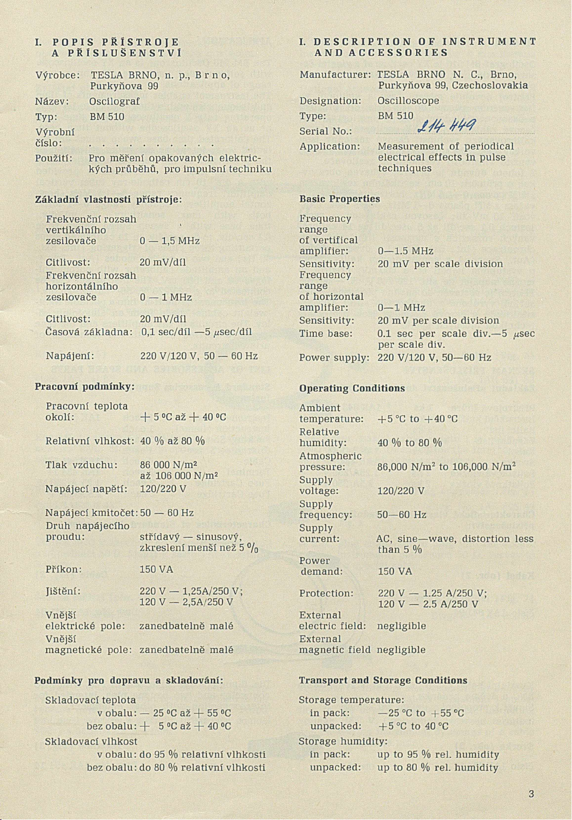
Prístroj dovoluje mérení éasu a kmitoctü va
frekvenéním pásmu do 1,5 MHz pfi provozu
s casovou základnou jako Y oscilograf; bez
casové základny jako XY oscilograf. Hodnoty
kalibrovanych rychlostí casové základny jsou
voleny tak, aby pfi mérení było maximálné
vyuzito vlastností vertikálního zesilovace.
Z tohoto düvodu je prístroj vybaven obrazov-
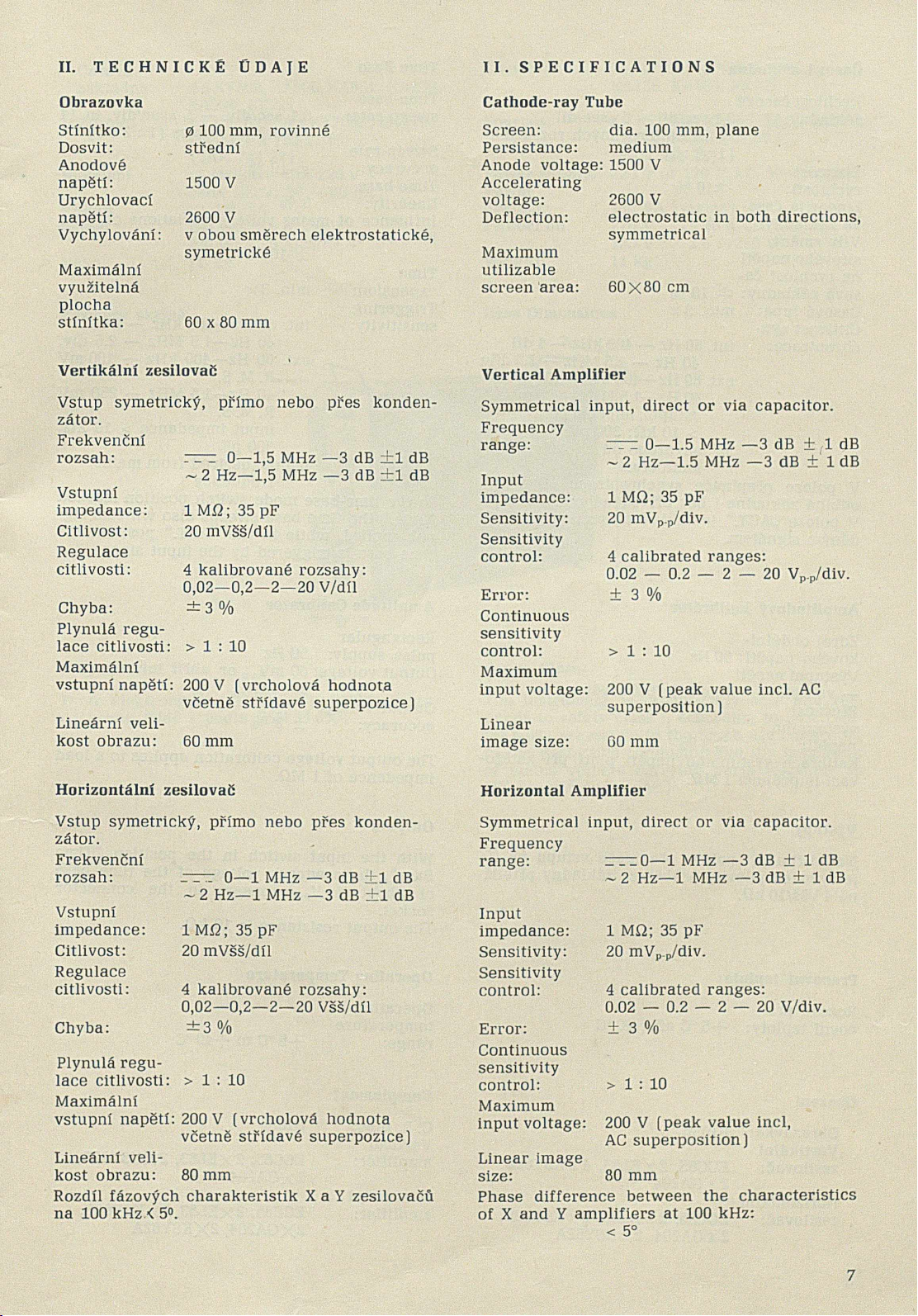
kou o prüméru 10 cm; vertikálním zesilovaéem
s sírí pásma 0—1,5 MHz; horizontálním zesilo-
vaéem s Sífí pásma 0—1 MHz, oba s max. citli-
vostí 20 mV/díl; casovou základnou o rych-
lostech 0,1 sec/díl aź 5 ¿¿sec/díl ve 14 kalibro
vanych rozsazích s mozností trí druhü syn-
chronizace (Int., Ext., 50 Hz) a dvou funkcích
(Aut., Synchr.) a amplitudovym kalibrátorem
o vystupním napétí 60 a 600 mV. Prístroj je
możno napájet ze sité 120/220 V, 50 — 60 Hz.
Prístroj je vestavén do snadno pfenosné, lehké
skfíné, vyrobené z hliníkovych slitin. Obvody
zesilovaéü a éasové základny jsou provedeny
technikou plosnych spojü.
The BM 510 Oscilloscope is an XY oscilloscope
with selfcontained time base offering a wide
range of applications.
The instrument enables measurements of time
and frequencies within the range up to 1.5 MHz,
operating as a Y oscilloscope with time base
or as an XY oscilloscope without time base.
The calibrated time-base sweep values are se
lected so as to ensure maximum utilization of
the properties of the vertical amplifier.
To achieve this, the instrument is provided
with a dia. 10 cm cathode-ray tube; vertical
amplifier, frequency range 0—1.5 MHz; hori
zontal amplifier, frequency range 0—1 MHz;
both with max. sensitivity 20 mV/div.;
time base with a sweep speed range from
0.1 sec/div. to 5 ,usec/div. in 14 calibrated steps
permitting three kinds of triggering (Int., Ext.,
50 Hz] and two operating modes (Aut., Trig.);
and an amplitude calibrator with output vol
tages 60 and 600 mV. The instrument can be
connected to a 120/220 V, 50—60 Hz, mains.
The instrument is built-in into a portable light-
-weight cabinet made from an aluminium al
loy. The circuits of the amplifiers and the time
base are carried out with the technique of'
printed circuits.
SEZNAM PRÍSLUSENSTVÍ
Základní príslusenství dodávané s prístrojem
LIST OF ACCESSORIES AND SPARE PARTS
Pfístrojová snûra 1 ks
Instrukíní knízka 1 ks
Balici list 1 ks
Zárucní list 1 ks
Kabel 4 ks
Svorka 2 ks
Pojistková vloáka 2 ks
Pojistková vloźka 2 ks
ÍAK 643 53
1AK 641 94
1AK 484 14
1.25A/250 V
2,5A/250 V
Charakteristické vlastnosti základního
príslusenství:
Kabel (obr. 2)
císlo 1AK64194
Obr. 2
Standard Accessories Supplied with
Instrument
Instrument Lead 1 each
Instruction Manual leach
Packing Sheet 1 each
Guarantee Sheet 1 each
Cable 4 each
Terminal 2 each
Fuse Cartridge 2 each
1AK 643 53
1AK 641 94
1AK 484 14
1.25 A/250 V
2.5 A/250 V
Characteristics of Standard Accessories
Cable (Fig. 2)
Dwg. No. 1AK 641 94
Fig. 2
Koaxiální kabel 060 délce 1 m, s konektorem
BNC a dvéma banánky.
Slouźi k propojeni s jinÿmi zafízeními.
Dia. 6 mm coaxial cable, length 1 m, with BNC
connector and two banana pins. Intended for
interconnection with other equipment.
Svorka (obr. 3)
Císlo 1AK 484 14 Obr. 3 Fig. 3
Terminal (Fig. 3)
Dwg. No. 1AK 484 14
4

Svorka BNC k zasunuti do z^suvky na pristroji, A BNC terminal to plug into the socket on the
opatrena pfechodem na ban6nek o 0 4 mm. instrument, provided with a dia. 4 mm banana
pin adapter.
Zvlastni prislusenstvi Optional Accessories
Toto pfisluSenstvi se s pfistrojem nedodävä, je
nutno je objednat u vyrobce zvlääf.
Charakteristicke vlastnosti zvlästniho
prislusenstvi:
Sonda BP 4B31 (obr. 4)
Cisło 1AK053 71/Z
Obr. 4
Pasivni dSłiCovś sonda s dślicim pomSrem
1 :10, vstupnim odporem 10 Mi2, vstupni kapa-
citou asi 7,5 pF. Slouzi ke zvStseni vstupniho
odporu a sniźeni vstupni kapacity.
Kabel (obr. 5)
cislo 1AK 641 63
Obr. 5
These accessories are not supplied with the
instrument and must be separately ordered
with the manufacturer.
Characteristics of Optional Accessories
BP 4631 Probe (Fig. 4)
Dwg. No. 1AK 053 71/Z
Fig. 4
Passive divider probe with a division ratio of
1 : 10, input resistance 10Mi2, input capacity
about 7.5 pF. Serves to increase the input re
sistance and to decrease the input capacity.
Cable (Fig. 5)
Dwg. No. 1AK 641 63
Fig. 5
Koaxiälni kabel 0 0 6 a delce 1 m se dvgma ko-
nektory BNC. Slouźi k propojeni vstupu s ji-
nymi zarizenimi.
Dia. 6 mm coaxial cable, length 1 m, with two
BNC connectors. Intended for the interconnec
tion of input with other equipment.
Vidlice (obr. 6)
cislo 1AF 895 43
Obr. 6
Vidlice BNC k zasunuti do zäsuvky na pristroji
o impedanci 50 Q. Slouzi k sestaveni zvlästniho
kabelu.
Plug connector (Fig. 6)
Dwg. No. 1AF 895 43
F i g . 6
A BNC plug connector to plug into the socket
on the instrument, impedance 50 O. Serves to
build up a special cable.
Svorka merici (obr. 7)
cislo 1AF 850 89
Obr. 7
Svorka umoźńujici mgfeni na menS pristup-
nych mistech. Umozńuje trvalś pripojeni k m§-
renśmu objektu. Izolaćni napöti 1000 V. Propo
jeni mezi svorkou a mgricim pfistrojem pomoci
sfiüry s banśnkem 0 4 mm.
Measuring Terminal (Fig. 7)
Dwg. No. 1AF 850 89
Terminal facilitating measurements at uneasily
accessible points. Enables permanent connec
tion to the object being measured. Insulating
voltage 1000 V. Connection between terminal
and measuring instrument by means of a cable
with 4 mm banana pin.
5

SEZNAM NÂHRADNlCH DÎLÛ
Nâzev Vzhled — Funkce — Oznaceni Cislo vÿkresu Poznâmka
Knoflik sedÿ, se znackou, neprüch. 0 25 1AF 244 32 pro hridel 06
Knoflik sedÿ, neprûchozi, 0 12 1AF 244 97 pro hridel 06
Knoflik sedÿ, se znaôkou, prûch. 0 18 1AF 243 20 pro hridel 06
Knoflik cervenÿ, se znackou, 012 1AF 244 35 pro hridel 03
Knoflik §edÿ, se znackou, 0 16 1AF 244 00 pro hridel 06
Zâtka bilâ, 0 13 1AA 425 38
Zâtka bilâ, 0 10 1AA 425 37
Knoflik êedÿ, bez znacky, 0 16 1AF 243 99 pro hridel 06
Deska rastr s dëlenim 1AA 202 01
Deska svëtelnÿ filtr 1AA 201 87
Vypinac dvojpôlovÿ sifovÿ vypinaë 1AN 569 26
Objimka objimka obrazovky 1AK 497 48
Cepicka vÿvod urychlovaciho napëti
obrazovky 1AF 350 10
Noźka nozka 1AF 261 54
Zârovka iârovky k osvëtleni rastru 1AN 109 46
Zârovka kontrolni Zârovka 1AN 109 17
PPepinac S202 1AK 536 14
Prepinac S302 1AK 536 15
Tlacitko S2 1AN 559 58
Prepinaë S102, S103 1AK 536 32
Prepinac S201,S203, S301, S303 1AK 536 33
RadiC S101 1AN 553 17
Transformator sifovÿ transformétor 1AN 663 62
Matice matice pro prichyceni râmecku
obrazovky 1AA 047 59
LIST OF SPARE PARTS
Designation Aspect-Function-Marking Dwg. No. Remark
Knob grey, with index, full-type
dia. 25 mm 1AF 244 32 for 6 mm shaft
Knob grey, full-type, dia. 12 mm 1AF 244 97 for 6 mm shaft
Knob grey, with index, through-type,
dia. 18 mm 1AF 243 20 for 6 mm shaft
Knob red, with index, dia. 12 mm 1AF 244 35 for 3 mm shaft
Knob grey, with index, dia. 16 mm 1AF 244 00 for 6 mm shaft
Cover cap white, dia. 13 mm 1AA 425 38
Cover cap white, dia. 10 mm 1AA 425 37
Knob grey, without marking, dia. 16 mm 1AF 243 99 for 6 mm shaft
Plate graticule with divisions 1AA 202 01
Plate light filter 1AA 201 87
2-pole switch mains switch IAN 569 26
Holder cathode-ray tube holder 1AK 497 48
Cap CR tube accelerating potential outlet 1AF 350 10
Pin tube holder pin 1AF 261 54
Lamp graticule illumination incandescent
lamp IAN 109 46
Lamp pilot lamp IAN 109 17
Switch S202 1AK 536 14
Switch S302 1AK 536 15
Slide switch S2 IAN 559 58
Switch S102, S103 1AK 536 32
Switch S201, S203, S301, S303 1AK 536 33
Multi-step switch S101 1AK 553 17
Transformer mains transformer IAN 663 62
Nut CR tube frame fastening nut 1AA 047 59
6

II. TECHNICKÉ ÜDAJE
Obrazovka
0 100 mm, rovinné
stredni
Stinitko:
Dosvit:
Anodové
napëti: 1500 V
Urychlovaci
napëti: 2600 V
Vychylovâni: v obou smôrech elektrostatické,
symetrické
Maximâlni
vyuzitelnâ
piocha
stinitka: 60 x 80 mm
I I . SPECIFICATIONS
Cathode-ray Tube
Screen: dia. 100 mm, plane
Persistance: medium
Anode voltage: 1500 V
Accelerating
voltage: 2600 V
Deflection: electrostatic in both directions,
symmetrical
Maximum
utilizable
screen area: 60x80 cm
Vertikalni zesilovac
Vstup symetricky, primo nebo pres konden-
zator.
Frekvencni
rozsah: rr~r 0—1,5 MHz —3 dB ±1 dB
~ 2 Hz—1,5 MHz —3 dB +1 dB
Vstupni
impedance: lM£>;35pF
Citlivost: 20 mVss/dil
Regulace
citlivosti: 4 kalibrovane rozsahy:
0,02—0,2—2—20 V/dil
Chyba: ± 3 %
Plynulci regu
lace citlivosti: > 1 : 10
Maximalni
vstupni napSti: 200 V (vrcholova hodnota
vgetnS stfidavg superpozice)
Linecirni veli-
kost obrazu: 60 mm
Vertical Amplifier
Symmetrical input, direct or via capacitor.
Frequency
range:
____0—1.5 MHz —3 dB ± 1 dB
~ 2 Hz—1.5 MHz —3 dB ± 1 dB
Input
impedance: 1 M£2; 35 pF
Sensitivity: 20 mVp.p/div.
Sensitivity
control: 4 calibrated ranges:
0.02 — 0.2 — 2 — 20 Vp.p/div.
Error: ± 3 %
Continuous
sensitivity
control: > 1 : 10
Maximum
input voltage: 200 V (peak value incl. AC
superposition)
Linear
image size: 60 mm
Horizontâlni zesilovaE Horizontal Amplifier
Vstup symetricky, primo nebo pres konden-
zâtor.
Frekvenôni
rozsah:
Vstupni
impedance:
Citlivost:
Regulace
citlivosti:
Chyba:
r-r-r 0—1 MHz —3 dB ±1 dB
~ 2 Hz—1 MHz —3 dB ±1 dB
1 MÎ2; 35 pF
20 mVss/dil
4 kalibrovane rozsahy:
0,02—0,2—2—20 VsS/dil
± 3 %
Plynulâ regu
lace citlivosti: > 1 : 10
Maximâlni
vstupni napëti: 200 V (vrcholovâ hodnota
vcetnë stridavé superpozice)
Lineârni veli-
kost obrazu: 80mm
Rozdil fâzovÿch charakteristik X a Y zesilovacü
na 100 kHz.< 5°.
Symmetrical input, direct or via capacitor.
Frequency
range: irrzO—1 MHz — 3 dB ± 1 dB
~ 2 Hz—1 MHz —3 dB ± 1 dB
Input
impedance: 1 Mi2; 35 pF
Sensitivity: 20 mVp.p/div.
Sensitivity
control: 4 calibrated ranges:
0.02 — 0.2 — 2 — 20 V/div.
Error: ± 3 %
Continuous
sensitivity
control: > 1 : 10
Maximum
input voltage: 200 V (peak value incl,
AC superposition)
Linear image
size: 80 mm
Phase difference between the characteristics
of X and Y amplifiers at 100 kHz:
< 5°
7

Rychlost Casove
zäkladny: 0,1 sec/dil — 5 ,usec/dil
ve 14 kalibrovan^ch rozsazich
(1:2:5)
Pfesnost
rychlosti: ±10 %
Linearita öaso-
ve zäkladny: 5 %
Vliv zmgny
sifoveho napöti
na rychlost Ca-
sove zäkladny: dt 10 %
Casovä lupa: min. 3x
Citlivost syn-
chronizace: int. 60 Hz — 400 kHz — 1 dil
40 Hz — 1,5 MHz — 2,5 dilu
ext. 60 Hz—400 kHz—100 mVeff
40 Hz—1,5 MHz—250 mVeff
vstupni impedance
> 10 kß; 300 pF
si£:odvozeno od sitovöho
kmitoßtu.
V poloze pfepinace synchronizace „Synchr.“
odbihä zäkladna i bez pfivedenöho signälu.
V poloze „AUT.“ je zäkladna spoustöna pfivä-
dönym signälem.
Casovä zäkladna
Time-base
sweep rate: 0.1 sec/div. — 5 /^sec/div. in 14
calibrated ranges (1:2:5)
Sweep-rate
accuracy: ± 10 %
Time-base
linearity: 5 %
Influence of mains voltage variations on time
base sweep rate:
± 10 %
Time
expansion: min. 3X
Triggering
sensitivity: int. 60 Hz—400 kHz — 1 div.
40 Hz—1.5 MHz — 2.5 div.
ext. 60 Hz—400 kHz — 100 mV
R. M. S.
40 Hz—1.5 MHz — 250 mV
R. M. S.
input impedance > 10 k£2;
300 pF
mains: derived from mains
frequency
In the time-base mode switch position marked
“Trig.“ the time base sweeps also with no sig
nal applied, while in the “AUT.“ position the
time base is triggered by the input signal.
Time Base
Amplitudovy kalibrätor
Zdroj obdelni-
koväho napöti: 50 Hz
V^stupni napäti
— volitelnö: 60mV§§; 600 mVss
Pfesnost
vystupniho
napgti: dz3 0/0
Kalibrace vystupniho napgti plati pfi zat£2o-
vaci impedanci 1 Mß.
Vystupy
Na zdifku pfi poloze pfepinafie vstupu na CZ
je vyveden pilovit^ prübäh ze zäkladny pfiblifc-
ng 4 V§ä/10 kQ.
Pracovni teplota:
Rozsah pra
covni teploty: + 5 °C az + 4 0 °C
Amplitude Calibrator
Rectangular
pulse supply: 50 Hz
Output voltage: 60 mVp.p or
600 mVD D
Output voltage
accuracy: ± 3 %
The output voltage calibration applies to a load
impedance of 1 MQ.
Outputs
With the input switch in the position “Time
Base“, the sawtooth voltage of the time base
of about 4 Vp.p appears in the connector
socket.
The output resistance is 10 k£2.
Operating Temperature
Operating
temperature
range: + 5 °C to -f-40 °C
Osazeni
Obrazovka: B10S6
Vertikälni
zesilovaö: ECC85, 2 x EL83, 4xKSY62B,
2 x GA204
Horizontalni
zesilovaö: ECC85, 2 x EL83, 2 x KSY62B,
2 x GA204, 2 x KSY62A
Complement
C. R. tube:
Vertical
amplifier:
Horizontal
amplifier:
B10S6
ECC85, 2XEL83, 2XKSY62B,
2XGA204
ECC85, 2XEL83, 2XKSY62B,
2XGA204, 2XKSY62A
8

Zdroje:
Casovâ
zâkladna:
Napâjeni
Pfikon
Jistëni
Vâha
3 x KF506, KF508, KA501, KA236,
KA504, KZ721
2 x KY702F, 8 x KY705F, 6NZ70,
KZZ74, 8 x T53 11/60
(1AN 744 22)
ze stridavé sitë 220 V
nebo 120 V, 50 — 60 Hz
s if 150 VA
120 V 2,5 A/250 V
220 V 1,25 A/250 V
11 kg
Time base:
Sources:
3XKF506, KF508, KA501,
KA236, KA504, KZ721
2XKY702F, 8XKY705F, 6NZ70,
KZZ74, 8XT53 11/60
(1AN 744 22)
Power supply: 220 V or 120 V AC, 50—60 Hz
Power
demand: 150 VA (mains)
Protection: 220 V 1.25 A/250 V
Weight: 120 V
11 kg
2.5 A/250 V
Fig. 8
Obr. 8
32
Rozmëry skrinë Case Dimensions
Bezpeënostni trida
Tento elektronickÿ pristroj je proveden v bez-
pecnostni tridë I podle CSN 35 6501.
Safety Class
The instrument is intrinsically safe and res
ponds to safety class I. according to IEC. (Me
tal parts accessible to the touch are connected
to the protective conductor and the insulation
of mains voltage carrying parts responds to
IEC recommendations.)
9

VZHLED PÎtïSTROJE A ROZMÎSTËNÎ PRVKÜ ASPECT OF INSTRUMENT AND DISLOCATION
OF ELEMENTS
Pohled na predni panel View oî Face Panel
Obr. 9 Fig. 9
10

Pohled na zadni panel pfistroje View ol Rear Panel
11

Seznam ovlâdaclch a nastavovacich prvkü
a oznageni funkce
R24 „Jas“
R33 „Ostfeni“
R119 „Citlivost“ — plynulś zmgna
citlivosti
R240 „Vyrovnśni nuly Y“
R248 „Kai. Y“ — plynuld zmgna
citlivosti Y
R254, R255 „Posuv Y“
R340 „Vyrovnani nuly X“
R348 „Kai. X“, „Kai. CZ“ — plynulś
zmgna citlivosti X
R354, R355 „Posuv X“
R263 „Kalibrace citlivosti Y“
R363 „Kalibrace citlivosti X“
SI Sifovy vypinac
S2 „Rastr“ — pfepinag osv6tleni
rastru
S101 „gas/dil“ — pfepinag rychlosti
gasove zdkladny
S102 „Vyp; Aut; Synchr.“— pfepinag
funkci gasovś zśkladny
S103 „Int; Ext; 50 Hz“ — pfepinag
druhu synchronizace
S201 „
------
; 0“ — prepinag
vstupu Yl
S202 „V/dil“ — prepinac vstupniho
dSlige zesilovage Y
S203
------
; 0“ — pfepinag
vstupu Y2
S301 _ . _; 0“ — pfepinag
vstupu XI
S302 „V/dil“ — pfepinag vstupniho
dglige zesilovage X
S303
____; 0“ — pfepinag
vstupu X2
FI „600 mV“— vystup kalibragniho
napgti
F2 „60 mV“ — vystup kalibragniho
napgti
F101 „Ext“ — vstup externi syn
chronizace
F201 „Yl“ — vstup zesilovage Y
F202 „Y2“ — vstup zesilovage Y
F203 „±- — zemnici zdifka
F301 „XI“ — vstup zesilovage X
F302 „X2“ — vstup zesilovage X
F303 „ i ” — zemnici zdifka
F304 „_/l“ — vystupni zdifka
PI Pojistka sit!ovśho napgti
W1 Volig sifovśho napgti
N1 Sitovd pfivodka
List of Control and Calibrating Elements and
Functional Description
R24 “BRIGHTNESS“
R33 “FOCUS“
R119 “TRIG. SENSITIVITY“ — continuous
adjustment of triggering sensi
tivity
R240 “DC BALANCE“ — zero adjustment
Y
R248 “Y CAL.“ — continuous adjustment
of Y sensitivity
R254,R255“Y SHIFT“
R340 “DC BALANCE“ — zero adjustment
X
R348 “X CAL.“, “T. B. CAL.“ — continuous
adjustment of X sensitivity
R354, R355“X SHIFT“
R263 “GAIN ADJ.“ — sensitivity calibra
tion Y
R363 “GAIN ADJ.“ — sensitivity calibra
tion X
51 “MAINS“ — mains switch
52 “GRAT.“ — graticule illumination
switch
5101 “TIME/DIV.“ — time-base sweep-ra-
te switch
5102 “OFF“, “AUT“, “TRIG.“ — time-base
mode switch
5103 “INT.“, “EXT.“, “50 Hz“ — trigger
ing mode switch
5201 “0“ — Y1 input switch
5202 “V/DIV.“ — input divider switch of
Y amplifier
5203 “rr-z “, “0“ — Y2 input switch
5301 “rr— “0“ — XI input switch
5302 “V/DIV.“ — input divider switch of
X amplifier
5303 “0“ — X2 input switch
FI “600 mV“ — calibrating voltage
output
F2 “60 mV“ — calibrating voltage
output
F101 “EXT.“ — external triggering
input
F201 “Y l“ — Y amplifier input
F202 “Y2“ — Y amplifier input
F203 "±" — earthing socket
F301 “XI“ — X amplifier input
F302 “X2“ — X amplifier input
F303 "±” — earthing socket
F304 u_yL" _ output socket
PI mains voltage fuse
WL mains voltage selector
N1 mains receptacle
12

Pohled na levou stranu pristroje View of Left-Hand Side of Instrument
Pohled na pravou stranu pristroje View of Right-Hand Side of Instrument
Obr. 12
Ovladaci prvky vertikalniho zesilovafie
Vyrovndni nuly
potenciometry na dostaveni rovnovśhy
zesilovaće, k odstranSni posuvu stopy
pfi otśceni potenciometrem plynulć
zmgny citlivosti.
Posuv Y umoźńuje vertikślni posouvśni stopy
po plośe stinitka.
Fig. 12
Vertical Amplifier Control Elements
DC BALANCE — balance restoring potentiome
ters to remove the trace shift occurring
when turning the continuous sensitivity
adjustment potentiometer.
Y SHIFT — potentiometer enabling vertical
shift of the trace on the screen.
13

Pfepinac vstupniho dëlice V/dil
frekvencnë kompenzovanÿ dëlic, umis-
tënÿ na vstupech zesilovacü, kterÿ ve
ctyfech polohâch umożfiuje kalibro-
vanou zmënu citlivosti.
Pfepinac vstupu Y1
slouzi k volbë vazby stejnosmërné pri
mo nebo stfidavé pres oddëlovaci kon-
denzator nebo k uzemnëni vstupu Yl.
Pfepinac vstupu Y2
shodnë s Yl.
Vstup zesilovace Yl
Vstup zesilovace Y2
je urcen pro pfipojeni mëfeného nebo
kalibracniho napëti.
Plynulâ zmëna citlivosti
spfaźena se vstupnimi dëlici. Je-li vy-
2adovâna kalibrace citlivosti zesilova-
Cû, je nutno mit potenciometr vzdy
v poloze na pravém dorazu, ryskou
knofliku na znacce kalibrovâno.
Kalibrace citlivosti
pfipadné nesrovnalosti v citlivosti, pîi
potenciometru plynulé zmëny v poloze
„Kai. Y“, lze dostavit timto prvkem na
boku pfistroje.
Ovlâdaci prvky horizontâlniho zesilovace
Funkce prvkû je stejnâ jako u vertikâlniho ze-
silovaëe, pouze funkce pfepinace vstupniho dë
lice v pośledni poloze ,,Cz“ pfipoji interné na
zesilovaë pilovitÿ prübëh z casové zâkladny.
Casovâ zâkladna je kalibrovâna v levé krajni
poloze plynulé zmëny citlivosti X. V pravé
krajni poloze je zapojena casovâ lupa (3x).
Ovlâdaci prvky casové zâkladny
Rychlost casové zâkladny „ëas/dil“
kalibrovanâ zmëna rychlosti casové
zâkladny v pomëru 1:2:5, v roz-
sahu 0,1 sec/dii aź 5 ¿¿sec/dil.
Pfepinaë funkci Cz
synchronizovanâ, spoustënâ nebo vy-
pnutâ.
Pfepinac druhû synchronizace
z vertikâlniho zesilovaëe, ze zdifky na
pfednim panelu a ze sitë.
Ovlâdaci prvky k obrazovce
Jas regulace jasu stopy na stinitku obra-
zovky.
Ostfeni regulace ostrosti stopy na stinitku.
Rastr osvëtleni rastru pfed obrazovkou.
V/DIV. — input divider switch — a frequency-
-compensated divider connected in the
amplifier inputs enabling calibrated sen
sitivity selection.
Yl — input selector switch providing either
DC direct coupling or AC coupling via
blocking capacitor or connection of Yl
input to earth.
Y2 — input selector switch identical with Yl.
Yl, Y2 — input sockets intended for the con
nection of the voltage being measured or
of the calibrating voltage.
Y CAL. — continuous sensitivity adjustment
coupled with input dividers. If the sensi
tivity of the amplifier is to be calibrated,
the potentiometer must be always turned
to the extreme right to make the knob
index point to the “Y CAL.“ sector.
GAIN ADJ. — any sensitivity irregularities oc
curring with the continuous sensitivity
adjustment potentiometer in the “Y CAL.“
position can be removed by means of this
element on the side of the instrument.
Horizontal Amplifier Control Elements
The function of the elements is the same as in
the case of the vertical amplifier, the only dif
ference being in that the input divider switch
in its extreme position “T. B.“ provides for the
internal connection of the time-base sawtooth
voltage to the amplifier. The time base is cali
brated in the extreme left position of the con
tinuous X-sensitivity adjustment potentiometer.
The time expansion (3X) is in action in the
extreme right position of this potentiometer.
Time Base Control Elements
TIME/DIV. — time-base sweep rate — calibra
ted stepwise change of the sweep rate at
a ratio of 1:2:5 within the range off
from 0.1 sec/div. to 5,usec/div.
TIME BASE (S102) — time-base mode switch —
automatic, triggered or off.
TIME BASE (S103] — triggering mode switch
— time base triggered by vertical ampli
fier, from the socket on face panel or by
the mains.
CR Tube Control Elements
BRIGHTNESS — brightness control of the tra
ce on the screen.
FOCUS — focussing of the trace on the screen.
GRAT. — illumination of the graticule plate
over the screen.
14

POKYNY PRO UVEDENÎ PRISTROJE DO CHODU INSTRUCTIONS FOR SETTING IN OPERATION
Umisteni pfistroje
Pfistroj umistëte tak, aby byl dostatecnÿ pfi-
stup vzduchu do pfistroje a nedochâzelo ke
zbytecnému pfehfâti a tim ke zhorseni vlast-
nosti pfistroje.
Pripojeni na sit'
Pfed pfipojenim na sit se pfesvëdcte, zda je
pfistroj pfepojen na sprâvné sifové napëti na
volici. Pfipadné chybnë nastavené napëti pfe-
pojte volicem do sprâvné polohy. Pfepojeni se
provédi prepinacim kotoućkem, kterÿ vytâhnë-
te a zasuńte tak, aby cislg, udâvajici napëti,
bylo proti trojühelnikové znacce na zadnim
stitku. Pfistroj je od vÿrobce nastaven na na-
pëti 220 V. Pfi pfepojeni na 120 V je tfeba vy-
mënit téz sifovou pojistku. Hodnoty pojistek
pro obë napâjeci napëti jsou uvedeny v rubrice
„TECHNICKÉ ÛDAJE“.
Kontrola chodu pfistroje
Zasuhte sitovou sńuru do pfivodky a do sifove
zastrćky. Vypinafi musi byt v poloze „0“; vse-
chny knofliky, zvlastg „Jas“ (R24) v poloze
max. vytocene doleva. RovnSz vypinac „Rastr“
musi byt v poloze „0“. Vsechny vstupy zesilo-
vacu pfepngte do polohy „0“. Prepinac v hori-
zontólnim zesilovaci pfepngte do polohy ,,CZ“;
prepinac volby synchronizace do polohy „Int“;
druh cinnosti casove zśkladny do polohy
„SYNCHR.“ a potenciometr jemnś regulace ze-
sileni horizontalniho zesilovace do polohy
„Kai. CZ“.
Pfepnëte vypinac do polohy „1“. Tim se roz-
sviti signalizacni zârovka, kterâ signalizuje,
ze pfistroj je v provozu.
Zapnëte vypinaëem „Rastr“ osvëtleni rastru.
Pfibliznë po jedné minutë se objevi stopa, jejiż
polohu „Jas“ a „Ostrost“ sefid'te potenciometry
„PosuvY“ (R254, R255); „Jas“ (R24); „Ostfeni“
(R33) a „Posuv X“ (R354, R355).
Spojovacim kâblikem propojte vÿstup kalibrâ-
toru „60 mV“ se vstupem vertikâlniho zesilo-
vaëe, oznacenému „Y1“ a tento pfepnëte do
polohy „ i r r “. Nastavenim potenciometru
jemné regulace zesileni vertikâlniho zesilovace
do polohy „Kal. Y“ dostanete na stinitku obdél-
nikové prübëhy (velikost 3 dilky). Pfipadnou
nesrovnalost v amplitudë lze dostavit prvkem
„Kalibrace citlivosti“, pfistupnÿm na levém
boku pfistroje. Pfepinânim rychlosti casové zâ-
kladny se pak mohou volit rüznâ mëfitka roz-
vinuti horizontâlniho dëje. Nastaveni potencio
metru jemné regulace zesileni horizontâlniho
zesilovace do polohy „Kal. X“ pouzivâme pfi
Location of Instrument
When locating the instrument, provide for a
sufficient access of air to its interior to pre
vent undersirable overheating, which would
cause worsening of the instrument properties.
Connection to Mains
Before connecting the instrument to mains,
see that the mains voltage selector is preset
to the correct value. In the case of incorrect
presetting change the selector to the desired
position. To do this, withdraw the selector
disk and reinsert it so that the number indi
cating the mains voltage lies opposite the tri-
angle-shaped index on the back plate. The
manufacturer presets the mains voltage to
220 V. When changing to 120 V it is also ne
cessary to replace the mains fuse. The fuse
values for the two mains voltages are indica
ted in the “SPECIFICATIONS“.
Operation Check
Insert the mains lead into the instrument re
ceptacle and then into the mains socket. The
mains switch must be in its “0“ position and
all the knobs, particularly the “BRIGHTNESS“
knob (R24), are to be turned to their extreme
left. The “GRAT.“ switch must likewise be in
its “0“ position. Now return all the amplifier
input switches to their “0“ positions. To pro
ceed, change the input divider switch of the
horizontal amplifier to the position “T. B.“,
the triggering mode switch to the position
“INT.“, the time-base mode switch to the po
sition “TRIG.“ and the fine gain-adjustment
potentiometer of the horizontal amplifier to
the position “T. B. CAL.“.
Now trip the mains switch to the position “1“.
This causes the pilot lamp to light up to indi
cate that the instrument is in operation.
Close the “GRAT.“ switch to illuminate the
graticule. The electron trace appears on the
screen in about one minute. Adjust its posi
tion, brightness and sharpness with the aid
of the potentiometers “Y SHIFT“ (R254, R255J,
“BRIGHTNESS“ (R24), “FOCUS“ (R33] and
“X SHIFT“ (R354, R355).
Use a cable to interconnect the “60 mV“ cali
brator output with the vertical amplifier input,
marked “Y l“, and switch it to the position
„ r m “. Set the fine gain-adjustment potentio
meter of the vertical amplifier to the position
“Y CAL.“ to obtain rectangular pulses on the
screen (magnitude 3 divisions]. Amplitude
deviations, if any, can be removed with the
element marked “GAIN ADJ.“ accessible from
the left side wall of the instrument. Diverse
scales of development of the horizontal pro
cess can then be selected by changing the
sweep rate of the time base. The fine gain-
adjustment potentiometer of the horizontal
15

tomto druhu provozu ćas. łupu, umoźiiujici roz-
vinuti prubghu s 3x vyssi rychlosti. Obraz do
synchronniho stavu nastavime potenciometrera
„Citlivost“ (R119).
IV. z p Os o b y m Er e n !
PRlKLADY OBSLUHY V PROVOZU S CASOVOU
ZAKLADNOU
Mereni stfidave slożky napeti
Mgfime-li stfidavou slozku napgti, nastavime
funkćni pfepinag S201 do polohy S203 do
polohy „0“. V teto poloze je stridavd sloźka
pozorovaneho prubghu zobrazena na stinitku.
Je-li frekvence mgfenś stfidavg slożky pozoro
vaneho prubghu pfilis nizkś, provddime mgreni
v poloze pfepinace „ “z duvodu omezeni
chyb. PfisluSnou velikost stfidave slożky na
pgti Ss dostaneme takto:
Na rastru pomoci dilkoveho dgleni odecteme
velikost od kladneho po zśporny vrchol pru
bghu v dilclch. Takto ziskan^ rozmgr nśsobime
udajem, ktery je dśn polohou knofliku „V/dil“
zesilovace, pfićemż potenciometr jemne regu-
lace zeslleni musi byt v poloze „Kai. Y“.
Ndsobime jestg dglicim ćinitelem sondy, po-
uźitś pro ziskśni mgfenśho napgti. Vyslednd
velikost napgti tedy je: dglici pomgr sondy
x V/dil x vyśka obrdzku = napgti Ss. Pro n&-
zornost pfedpokl&dejme pouźiti sondy BP 4631
s dglicim pomgrem 1 :10, knoflik „V/dil“ v po
loze 2 V, v^ska ohrśzku na stinitku dle rastru
je 4 dilky. 10 . 2 . 4 = 80 Vss
Mgrime-li sinusove prubghy, ziskane napgti
pi’evedeme z napgti Spieka—Spieka na efek-
tivni nebo stredni hodnotu obvykl?m zpuso-
bem.
Mereni okamźite hodnoty napeti
Mgfici metoda k mgreni okamźite hodnoty na
pgti je v podstatg shodna s metodou popsanou
v mgreni stfidave slożky napgti. Pfepinac
vstupu zesilovaie S201 pfepneme do polohy
„ “. Mgfime-li okamżitou hodnotu napgti
ve vztahu k ngjakemu potenciślu (obvykle
k zemnimu), musime si pfedem nastavit pfi-
sluSnou uroveii referencniho napgti, odpovi-
dajici velikosti na stinitku. Je-li napf. provś-
dgno mgfeni na + 100 V potenciślu, referenini
uroveft zemg. Jinś uroveil muże byt pouźita
zeni teto urovng popiSeme pro nejbgźngjśi
uroveft zemg. Jin& uroveii mfiże byt pouźita
obdobng.
amplifier can be turned to the position “X CAL.“
to start the time magnifier, which triples the
sweep rate. The image can be synchronized
by means of the “TRIG. SENSITIVITY“ poten
tiometer (R119).
IV. METHODS OF MEASUREMENT
EXAMPLES OF TIME-BASE OPERATION
Measurement of the Alternating Component of
a Voltage
If the alternating component of a voltage is to
be measured, set the input switch S201 to the
position and the input switch S203 to the
position “0“. The alternating component of the
course being observed is now displayed on the
screen. If the frequency of the alternating
component being measured is too low, perform
the measurement with the switch in the po
sition “ r t o reduce the errors. The corres
ponding peak-to-peak voltage of the alternat
ing component is evaluated as follows:
Read off the distance between the positive and
the negative peak in terms of the graticule
divisions. Multiply the magnitude so obtained
by the value indicated by the position of the
“V/DIV“ knob of the amplifier, the fine gain-
adjustment potentiometer being in the position
“Y CAL.“.
Now multiply the product obtained by the fac
tor of the probe used to detect the voltage
being measured. The resulting voltage is thus:
probe factorxV/DIVximage height = p-p vol
tage.
To illustrate the calculation, let us assume the
use of the BP 4631 probe with a division ratio
of 1 : 10, the “V/DIV“ knob to be in the posi
tion 2 V, and the screen image height in terms
of the graticule divisions to be 4 divisions:
10X2X 4 = 80 Vp.p
if sine-wave effects are being measured, the
usual methods are used to convert the peak-
-to-peak value to the R. M. S. or mean value.
Instantaneous Voltage Measurement
In its principle, the instantaneous voltage me
asuring method is identical with that descri
bed above. Change the amplifier input switch
S201 to the position “^zrz“. If the instantan
eous voltage value is to be measured with re
ference to a given potential (usually the earth
potential), it is essential first to preset the
appropriate reference voltage level correspond
ing to the size of the image. If, for inst., the
measurement proceeds at + 100 V potential,
the reference level will also correspond to
- j - 100 V. The provision of this reference level
will be described for the most frequently used
earth potential. Any other level can be attai
ned by analogy.
16

Ziskâni referenćni ûrovnë
Referenćni ûroven ziskâme nâsledujiclm po-
stupem:
Pripojime hrot sondy na zemni s vor ku na pri-
stroji [nebo na pfislusnÿ zdroj napëti, je-li
üroven jinâ nez zem) a nastavime oscilograf
na volnë bëzici zâkladnu. Je-li jako referenćni
üroven zvolen zemni potenciâl, lze też pouźity
vstup pfepnout pfepinacem S201 do polohy „0“.
Vertikélnë nastavte stopu na stinitko tak, aby
lezela na nëkteréni z hlavnich dilkû rastru
(tento bod nastaveni bude zâviset na polarité
a amplitude vstupniho signélu, event, na po-
uzitém vstupu zesilovace). Tento dilek rastru
je pak referenćni ûrovni pro vsechna dalsi
mëreni. Po nastaveni referenëni ûrovnë uż ne-
nastavujeme vertikâlni posuv, nebot: by do më-
feni była zanesena chyba.
Hrot sondy pripojime na zdroj mëficiho napëti.
Ovlâdaci prvek „Citlivost“ (R119) nastavime
tak, aby obraz byl stabilni.
Na rastru odmërime vzdâlenost pozorovaného
bodu na prûbëhu od bodu, kterÿm probihâ re
ferenćni ûroven v dilci. Tento rozmër nâso-
bime iidajem, kterÿ je dân polohou knofliku
„V/dil“.
Nśsobime jeStS dćlicim pomorem poużitś sondy.
Pro nazornost predpokladejme pouźiti sondy
BP 4631 s dglicim pomgrem 1 :10. Knoflik V/dil
v poloze 0,2; referenćni uroveii je nastavena
na druhou rysku od spodku rastru a od tohoto
bodu je vzdalenost 3 dilky k bodu prubćhu, ve
kterem chceme mgfit okamżitg napgti. Potom
bude: 10 x 0,2 x 3 = 6 V. Je-li mereny napefovy
bod nad rovinou referenćni urovne pri pouziti
vstupu „Yl“, je polarita napćti kladna; je-li
pod urovni, je zśpornś. Pri pouźiti vstupu „Y2“
je polarita napśti opaćna.
Mereni Casu
Casova zśkladna poużitd v pfistroji umozńuje
zjistit casovy interval mezi dvema prubghy
nebo dvgma body jednoho prubShu aż do dślky
rastru. Takove mćreni se provddi nasledujicim
zpusobem:
Na rastru odecteme horizontalni vzdalenost
mezi dvgma body, jejichż casovy interval ode
cteme v dilcich.
Tuto vzddlenost nasobime koeficientem, ode-
Ctenym v poloze knofliku „ćas/dil“ pouźite ca-
sove zakladny. Potenciometr jemne regulace
zesileni horizontślniho zesilovaCe nastavime
do polohy „Kai. ĆZ“.
Pro nśzornost predpokladejme, źe prepinac
„cas/dil“ je v poloze 1 msec; horizontalni vzd&-
lenost, odectena na rastru, je 5 dilku. Casovy
interval potom bude:
5 x 1 msec = 5 msec.
Provision of Reference Level
The reference level is provided as follows:
Insert the probe point into the earth terminal
of the instrument [or connect it to the desired
voltage supply, if the level is other than earth)
and set the oscilloscope to allow the time base
sweep freely. If the earth potential is chosen
as reference level, the input used can also be
switched to “0“ by means of the switch S201.
Adjust the vertical setting to make the elec
tron trace coincide with one of the main gra
ticule divisions (the preset point will depend
on thet polarity and amplitude of the input
signal and on the amplifier input chosen).
This graticule division now serves as reference
level in all subsequent measurements. After
having preset the reference level, avoid any
adjustment of the vertical shift, since this
would infer error into the measurement.
Apply the point of the probe to the source of
the voltage being measured. Set the “TRIG.
SENSITIVITY“ potentiometer (R119) so as to
obtain a stable image.
Now measure the distance of the point being
observed on the curve from the reference le
vel point in terms of graticule divisions. Mul
tiply this distance by the value indicated by
the position of the “V/DIV.“ knob. Moreover,
multiply the product so obtained by the divi
sion ratio of the probe used.
To illustrate the calculation, let us assume the
use of the BP 4631 probe with a division ratio
of 1 : 10, the “V/DIV.“ knob being in the posi
tion 0.2. Let the reference level be adjusted
to the second graticule division from below,
the distance from this point to the point on
the curve at which we wish to measure the
instantaneous voltage being 3 divisions. It fol
lows that: 10x0.2x3 = 6 V. If the “Yl“ input
is used and the measured voltage point is over
the reference level, the polarity of the voltage
is positive, and it is negative, if the said point
is below the reference level. When using the
“Y2“ input, the polarities are reverse.
Time Measurements
The time base used in the instrument enables
to evaluate the time interval between two cur
ves or between two points of the same curve,
the limit being imposed by the length of the
graticule. The measurement of this kind pro
ceeds as follows:
Read off the horizontal distance between two
points on the graticule in terms of divisions.
Multiply this distance by the factor indicated
by the position of the “TIME/DIV.“ knob of
the time base. Set the fine gain-adjustment
potentiometer of the horizontal amplifier to
the position “T. B. CAL.“.
To illustrate the evaluation, let us assume the
“TIME/DIV.“ switch to be in the position
1 msec, the horizontal distance read off the
graticule being 5 divisions. The time interval
will then be: 5 x 1 msec = 5 msec.
17

Pfi poloze „Kai. X“ potenciometru jemne regu-
lace zesileni X je pouźita casovś lupa pfiblizng
3x. V tomto pfipadS pfi stejnS odecten^ch uda-
jich jako ve v^se uvedenem pfipadS je casovy
interval 1 x 5 ,
----
-
-----
---
1,66 msec
With the fine gain-adjustment potentiometer
of the X amplifier in the position “X CAL.“,
the time expansion of about 3 x is in opera
tion. Assuming the same readings as before,
the time interval will in this case be
— — 1-66 msec
Mefeni frekvence
MSfeni frekvence provddime stejn^m zpuso-
bem jako mSfeni casu. Frekvenci pozorova-
neho prubehu dostaneme matematick^m uko-
nem, protoźe frekvence je pfevratnou hodnotou
ćasu periody. Pro ndzornost pfedpoklddejme
gas jednś periody 2 (xsec. Frekvence pozorova-
neho próbghu je pak:
...
.
■ = 0,5 x 10⁶ Hz = 0,5 MHz
Frequency Measurements
The frequency measurement proceeds in the
same way as the time measurement. The fre
quency of the process being observed is ob
tained by computation, since it is the inverse
value of the cycle period. To illustrate, let us
assume the cycle period to be 2 ¿¿sec. The fre
quency of the process being observed is then:
. J . . , = 0.5 X10⁶ Hz = 0.5 MHz
2X10
Mefeni syinetrickych signalu Measurement of Symmetric Signals
Obdobna mgfeni jak była uvedena v pfedchozi
kapitole lze provśd§t i se symetrickym signći-
lem. Pfitom symetricky signśl pfivśdlme do
obou vstupu vertikalniho zesilova£e.
PRlKLADY OBSLUHY V PROVOZU XY
Mefeni kmitoctu metodou Lissajousovych
obrazcu
Pfepinag S302 pfepneme do provozu s horizon-
tólnim zesilovacem a na vstup pfivedeme stfi-
dave napgti o znamem kmitoctu, napr. z RC
generdtoru Tesla BM 344. Na vstup vertikalniho
zesilovafie pfivśdime neznśmy kmitoget.
Jestliźe souhlasi kmitoćet generdtoru pfesng
s kmitoctem mgfenym, objevi se na stinitku
stojici obrazec. Mó-li mgfene napgti sinusovy
prubgh, je obraz kruźnice, elipsa nebo pfimka.
Pfi prubghu jinem (obdelnikovy, pilovy aj.) je
obraz na stinitku zkreslen.
Je-li jeden ze srovnśvacich kmitoćtu celistvym
nśsobkem druhśho, dostaneme jednoduche
obrazce, jejichż tvar se mgni vlivem fazoveho
posuvu. Na obrśzku jsou Lissajousovy obrazce
pro pomgr kmitoćtu 2 :1, 1 : 2, 4 :1.
Obr. 13
By analogy with the previous paragraph, a
symmetric signal can also be measured, being
applied to both inputs of the vertical amplifier.
EXAMPLES OF XY OPERATION
Frequency Measurements by the Method of
Lissajous Figures
Set the switch S302 for operation with hori
zontal amplifier and apply an AC voltage of a
known frequency, e. g., from the Tesla BM 344
RC generator, to its input. The unknown fre
quency is supplied to the input of the vertical
amplifier.
If the generator frequency agrees exactly with
the frequency being measured, a stationary
image appears on the screen. If the voltage
being measured is sinusoidal, the image is in
the form of a circle, an ellipse or a straight
line. For other wave forms [rectangular, saw
tooth, etc.) the image on the screen is dis
torted.
If one of the frequencies being compared is
an integer multiple of the other, simple figures
are obtained, the shape of which varies with
the phase shift. Lissajous figures for the fre
quency ratios of 2 : 1, 1 : 2, 4 : 1 are shown
in Fig. 13.
Fig. 13
fy : fx = 2 : 1 fy : fx = 1 : 2 fy : fx = 4 :1
Neni-li jeden z kmitoStu celistv^m nasobkem
druhśho, ale je-li pomgr vyjddfen pomgrem If one of the frequencies is not an integer
multiple of the other, but if their ratio can be
18
Table of contents
Other Tesla Test Equipment manuals