Tesmec AFS303 Installation and operating instructions
I
In
ns
st
ta
al
ll
la
at
ti
io
on
n,
,
o
o
H
H
a
a
P
Pu
ul
ll
le
er
r-
-T
Te
en
ns
si
i
o
o
o
o
p
pe
er
ra
at
ti
io
on
n
a
an
nd
d
m
ma
ai
in
nt
te
e
n
n
a
a
n
nd
db
bo
oo
ok
k
o
o
n
ne
er
r
M
Mo
od
de
el
l:
:
A
A
F
F
S
S
3
3
n
n
a
an
nc
ce
e
3
3
0
0
3
3

ATTENZIONE
Per motivi di sicurezza durante il trasporto la macchina è fornita senza olio idraulico e senza
carburante. Nel presente fascicolo troverete informazioni sulle caratteristiche e le quantità
richieste. In caso di dubbio consultare la TESMEC.
WARNING
The machine is supplied without hydraulic oil and fuel during transport for precautionary
measures. Please refer to this manual for all information regarding the characteristics and
quantities required. Should you have any doubt, please get in touch with TESMEC.
ATTENTION
Pour mesures de sécurité, pendant le transport la machine est livrée sans huile hydraulique
et sans carburant.
Référez-vous à ce manuel pour renseignements nécessaires sur les caractéristiques et
quantités. En cas de doute veuillez contacter TESMEC.
ATENCION
Por motivos de seguridad la máquina se transporta sin aceite hidráulico y sin combustible.
En el presente fascículo encontrarán informaciones acerca de las características y de las
cantidades requeridas. En caso de dudas, consultar a TESMEC.
ATENÇÃO
Por razões de segurança durante o transporte, a máquina é fornecida sem óleo hidráulico e
combustível. No presente folheto poderão encontrar as informações sobre as características
a as quantidades requeridas.
Caso tenham alguma dúvida, rogamos-lhes pôr-se em contacto com a TESMEC.
ACHTUNG
Aus Sicherheitsgründen während des Transportes, wird die Maschine ohne Öl und Kraftstoff
geliefert. Im vorliegenden Gebrauchsanweisungsheft werden Sie Informationen über die
Eigenschaften und Mengen des Öls finden.
Wenn Sie im Zweifel sind, fragen Sie TESMEC um Rat.
ПРЕДУПРЕЖДЕНИЕ
Из соображений безопасности, при поставке машина транспортируется без рабочей
жидкости вгидравлической системе итоплива.
Пожалуйста, пользуйтесь настоящим руководством для получения любых сведений,
касающихся характеристик изаправочных емкостей.
Вслучае каких-либо сомнений, пожалуйста, свяжитесь скомпанией ТЕСМЕК.
- 24050 Grassobbio (Bg) via Zanica, 17/O - 24060 Endine Gaiano (Bg) via Pertegalli
Tel. 0039 / 035 / 4232911 Tel. 0039 / 035 / 825024
Telefax 0039 / 035 / 4522445 Telefax 0039 / 035 / 826375

PULLER
-
TENSIONER
Model: AFS303
PULLER-TENSIONER
Model: AFS303
Serial number
………………
Manufacturing year
………………
Working order
………………
USE AND MAINTENANCE INSTRUCTIONS

PULLER-TENSIONER
Model: AFS303
Manual: MI-AFS303-320-00-GB
Date: 30.03.2015
Author: MC
Page: 1 of 32
1. GENERAL INDEX
Page
1. GENERAL INDEX 1
2. GENERAL DATA AND PRESCRIPTIONS 3
2.1 MANUFACTURER 3
2.2 COMMUNICATIONS WITH THE MANUFACTURER 3
2.3 TYPOLOGY AND USING FIELD 3
2.4 PERFORMANCES 3
2.5 TECHNICAL CHARACTERISTICS 4
2.6 ACOUSTIC EMISSION 4
2.7 GENERAL INFORMATION FOR THE MACHINE USE 4
2.8 GENERAL PRESCRIPTIONS FOR THE OPERATOR CHARGED OF THE MACHINE USE 4
2.9 GENERAL PRESCRIPTIONS FOR THE OPERATOR CHARGED OF THE MACHINE
MAINTENANCE 5
2.10 KNOWLEDGE AND CARE OF THE INSTRUCTION MANUAL 5
2.11 CONDITION OF USE 5
2.12 TEMPERATURE LIMITS FOR HYDRAULIC OIL 6
2.13 USE NOT ALLOWED 6
2.14 RESPONSIBILITY 7
2.15 APPLIED NORMS 7
3. TRANSPORT AND POSITIONING INSTRUCTIONS 8
3.1 MACHINE LIFTING 8
3.2 TRANSPORT TYPOLOGIES AND PACKAGE 8
3.3 UNPACKING 8
3.4 ASSEMBLING OPERATIONS 9
3.5 TRANSPORT ON TRAILER 9
3.6 POSITIONING AND ANCHORING 9
4. INSTRUCTION FOR USE 11
4.1 PRESCRIPTIONS FOR THE OPERATOR 11
4.2 CONTROLS 11
4.3 PRELIMINARY OPERATIONS 11
4.4 MACHINE SET-UP 12
4.5 ELECTRONIC MULTIFUNCTION DAVICE PAGES 13
4.6 STARTING OF THE MACHINE 14
4.7 PULL CONTROL 14
4.7.1 PULL LIMITING DEVICE SETTING 14
4.7.2 PULL PROGRAMMING DEVICE SETTING 15
4.8 CONNECTION MACHINE-HYDRAULIC HEAD OF THE REEL ELEVATOR OR REEL WINDER 16
4.9 PULLING OPERATIONS 16
4.10 RELEASING THE ROPE 17
4.11 COMPRESSOR CONNECTION (OPTIONAL) 17
4.12 PREHEATING KIT (OPTIONAL) 18
4.13 PREHEATING CONTROL PANEL PROGRAMMING (OPTIONAL) 18
4.13.1 GENERAL (OPTIONAL) 18
4.13.2 OPERATION (OPTIONAL) 18
4.13.3 SWITCHING THE HEATER ON (OPTIONAL) 19
4.13.4 SWITCHING THE HEATER OFF (OPTIONAL) 19
4.13.5 SETTING TIME/DAY OF THE WEEK (OPTIONAL) 19
4.13.6 VIEWING THE TIME (OPTIONAL) 19
4.13.7 PROGRAMMING HEATER STARTING TIME (OPTIONAL) 19
4.13.8 RECALLING/ERASING PRE-SET TIMES (OPTIONAL) 19
4.13.9 PROGRAMMING DURATION OF OPERATING TIME (OPTIONAL) 19
4.13.10 SETTING THE REMAINING OPERATING TIME (OPTIONAL) 19
4.13.11 SETTING THE WAKEUP TIME (OPTIONAL) 19
4.13.12 RECALLING/ERASING THE WAKEUP TIME (OPTIONAL) 20
4.14 ROPE LOCKING CLAMP (OPTIONAL) 20
4.15 POINTS TO REMEMBER 20

PULLER-TENSIONER
Model: AFS303
Manual: MI-AFS303-320-00-GB
Date: 30.03.2015
Author: MC
Page: 2 of 32
4.16 END OF THE OPERATIONS 20
5. INSTRUCTION FOR USE –CONNECTED MACHINES 21
5.1 GENERAL ASPECTS 21
5.2 MACHINES SET-UP 22
5.3 CONNECTED MACHINES OPERATIONS 23
5.4 PULL CONTROL SETTING 23
5.4.1 PULL LIMITING DEVICE SETTING 23
5.4.2 PULL PROGRAMMING DEVICE SETTING 23
5.5 USING OF ELECTRONIC SPEED SYNCHRONIZER DEVICE (OPTIONAL) 24
5.6 ROPE LOCKING CLAMP (OPTIONAL) 24
5.7 ALARM CONDITION WHEN USING CONNECTED MACHINES 24
5.7.1 STRINGING LENGTH ERROR 24
5.7.2 SWITCH ON THE MACHINE WITH CONTROL NOT IN NEUTRAL 24
5.7.3 EMERGENCY STOP 25
5.7.4 CAN-BUS DIS-CONNECTION BETWEEN THE MACHINES 25
5.7.5 ROPE-CLAMP POSITION 25
5.7.6 GEAR-BOX LOW-PULL POSITION 25
5.7.7 CONNECTION MACHINE SELECTOR 25
5.7.8 COMPONENT FAULT 25
6. SAFETY CONDITIONS 26
6.1 SAFETY DEVICES 26
6.2 EMERGENCY STOP DEVICE 26
6.3 PERIODIC OPERATIONS 26
6.4 RESIDUAL RISKS 27
7. MAINTENANCE 28
7.1 GENERAL PRESCRIPTIONS 28
7.2 LEVELS CONTROL 28
7.3 TYRES INFLATION PRESSURE 28
7.4 SUGGESTED LUBRICANTS 28
7.5 ENDOTHERMIC ENGINE MAINTENANCE 28
7.6 HYDRAULIC CIRCUIT MAINTENANCE 29
7.7 REDUCTION GEAR MAINTENANCE 29
7.8RADIATOR’S MAINTENANCE 30
7.9 GREASING 30
7.10 OTHER PERIODIC OPERATIONS 30
7.11 SUMMARY TABLE FOR ORDINARY MAINTENANCE 30
8. HOW TO DISABLE THE MACHINE 31
8.1 TRANSPORT 31
8.2 EXTENDED SERVICE STOP 31
8.3 STRIPPING 31
9. ENCLOSED DOCUMENTS 32
9.1 TABLES 32
9.2 SYSTEMS 32
9.3 OTHER DOCUMENTS 32

PULLER-TENSIONER
Model: AFS303
Manual: MI-AFS303-320-00-GB
Date: 30.03.2015
Author: MC
Page: 3 of 32
2. GENERAL DATA AND PRESCRIPTIONS
2.1 MANUFACTURER
TESMEC S.p.A.
Via Zanica, 17/O
24050 - GRASSOBBIO
BG - ITALY
tel. (+39)-035-4232911
fax (+39)-035-4522445
Via Pertegalli, 2
24060 - ENDINE GAIANO
BG - ITALY
tel. (+39)-035-825024
fax (+39)-035-826375
2.2 COMMUNICATIONS WITH THE MANUFACTURER
For any information related to the machine (use, maintenance, spare parts) always state Model, Serial
Number, Manufacturing Year and Order. These data can be found in the machine-identifying table.
2.3 TYPOLOGY AND USING FIELD
Puller-tensioner mod. AFS303 is suitable for stringing one bundled conductor with max. diameter of 36
mm and for recovering one rope with 10 mm in diameter with a connector with max. diameter of 28
mm.
The machine is controlled by a hydraulic system that allows the machine to automatically work in
PULLER or in TENSIONER mode.
The power transmission to the large groove bull-wheels is transmitted through a closed hydraulic
circuit with a variable delivery pump and fixed displacement motor, with the possibility to change
continuously the speed in both rotating directions.
A hydraulic vacuum brake stops automatically the two bull-wheels should the work be interrupted and
a damage in the hydraulic circuit occur.
The machine is equipped with rapid couplers for connection to all types of reel winders and reel
elevators made by Tesmec; the frame is complete with a rigid axle for towing at max. 30 km/h.
2.4 PERFORMANCES
PULLER PERFORMANCES
Max. pull 25 kN
Speed at max. pull 2,5 km/h
Max. speed 4,5 km/h
TENSIONER PERFORMANCES
Max. tension 25 kN
Max. speed 5 km/h
ATTENTION: the use with rope or conductor with diameter smaller than the max.
admitted one, will reduce the max. applicable pull in accordance with the min. granted
working load of the rope or of the conductor.
Performances are referred to the machine without optional, at sea level and at 20°C.

PULLER-TENSIONER
Model: AFS303
Manual: MI-AFS303-320-00-GB
Date: 30.03.2015
Author: MC
Page: 4 of 32
2.5 TECHNICAL CHARACTERISTICS
Bull-wheels diameter: 1500 mm with interchangeable nylon sectors
Diesel engine: 37,5 kW –3000 rpm –KOHLER KDW 2204
Electric system: 12 V
Transmission: closed hydraulic circuit with hydraulic oil cooling
Safety brake: negative and self-acting type
Dynamometer: hydraulic with set-point and automatic control of maximum pull
Axle: rigid type with mechanical parking brake for towing at a max.
speed of 30-km/h
Dimensions: length - 3680 mm
width - 1730 mm
height - 2770 mm
Mass without oil: 2600 kg
Mass with oil: 2740 kg
2.6 ACOUSTIC EMISSION
Level of continuous sound pressure to the operator seat (UNI 9432) Lep = 85 dB(A)
2.7 GENERAL INFORMATION FOR THE MACHINE USE
a. Only employed and qualified operators must use the machine.
Qualified operators is intended to be the person who has received a qualified training from the using
Company or, as alternative, from the manufacturer.
b. Machine must be used only for the work it was designed for.
c. Machine cannot be used with non-authorised personnel on the working site.
d. For safety reasons, during transport machine comes without hydraulic oil and fuel.
Characteristics and required quantities are listed in the present manual.
e. For any doubt concerning use, functioning, maintenance or everything else, contact the After-sales
Service of the manufacturer.
2.8 GENERAL PRESCRIPTIONS FOR THE OPERATOR CHARGED OF THE MACHINE USE
a. Operator has to know safety directives for accident prevention in force in the machine using
country, for a correct use of the same.
b. The operator in charge with the installation and maintenance of the machine must use suitable
clothes to the working site and to the situation where he finds himself; in particular he must avoid
the use of very large clothes, chains, bracelets, rings or whatever can get entangled with moving
parts.
c. The operator has to use the necessary protecting devices (i.e. gloves, boots, helmet, etc.).
It is compulsory the use of personal protecting devices for hearing.
d. The operator must not carry out on his own initiative operations or interventions that are not up to
him.
e. The operator must carefully follow danger and/or prohibition prescriptions contained in the
instruction manual or indicated on the machine.
f. The working area of the operator has to be cleaned from possible oil or liquids wastes and free of
materials or equipment that may be considered as on obstacle for the operator work.
g. The operator must absolutely avoid the direct inhalation of the exhaust gas of the endothermic
engine.

PULLER-TENSIONER
Model: AFS303
Manual: MI-AFS303-320-00-GB
Date: 30.03.2015
Author: MC
Page: 5 of 32
2.9 GENERAL PRESCRIPTIONS FOR THE OPERATOR CHARGED OF THE MACHINE
MAINTENANCE
a. It is absolutely forbidden to carry out any work of maintenance, adjustment or setting on units
while stringing (except for the operations indicated in the present manual).
b. Before carrying out any maintenance operations, stop the energy feeding (except for the cases
indicated in the present manual) and wait till the cooling of the elements subjected to heating.
c. All the maintenance operations of the machine must be carried out with machine on a level surface
and not under load.
d. Authorised and trained personnel must do all the maintenance operations, ordinary and not
ordinary. Trained personnel are intended to be the person who has received a qualified training
from the using Company or, as alternative, from the manufacturer.
e. The operator in charge with the machine maintenance must use suitable clothes to the working site
and to the situation where he finds himself; in particular he must avoid the use of very large
clothes, chains, bracelets, rings or whatever can get entangled with moving parts.
f. The operator has to use the necessary protecting devices (i.e. gloves, boots, helmet, etc.).
g. All the maintenance operations, ordinary and not ordinary, must be effectuated respecting the
prescriptions included in the present manual or following technical indications written by the
manufacturer. The non-respect of the prescribed restrains relieves the manufacturer from any
responsibility causing also the loss of warranty.
2.10 KNOWLEDGE AND CARE OF THE INSTRUCTION MANUAL
a. The information contained in the instruction manual applies to all the operators charged with the
use and/or the maintenance of the machine.
b. The instruction manual is not a training manual.
c. Before using the machine the chief of the job site and the operator must read the instruction
manual.
d. The chief of the job site is obliged to inform all the operators about the instructions contained in
the manual.
e. The user must carefully follow the instructions listed in the present manual.
f. Before using the machine, the operator must be able to use it and has to exactly know the
positions and the operations of all the controls.
g. The chief of the job site must verify that the instructions contained in the manual are applied.
h. The instruction manual must be kept, in order to be consulted, for all the life of the machine and
also when it is given to another user.
i. The instruction manual must be kept in a sheltered and dry place.
ATTENTION: present manual belongs exclusively to the manufacturer.
The reproduction, event partial, of the text is forbidden.
2.11 CONDITION OF USE
a. Temperature: from -10°C to +40°C.
b. Relevant moisture: from 30% to 90% 5%.
c. Weather conditions: any (in line with working conditions).
d. Natural and/or artificial lighting of the working site.
NOTE: the machine using and stocking is allowed till -20°C with preheating kit.

PULLER-TENSIONER
Model: AFS303
Manual: MI-AFS303-320-00-GB
Date: 30.03.2015
Author: MC
Page: 6 of 32
2.12 TEMPERATURE LIMITS FOR HYDRAULIC OIL
When using the machine, always remember to respect the following temperature limits that can be
reached with hydraulic oil as function of the working condition.
TEMPERATURE LIMITS FOR HYDRAULIC OIL (°C)
Working condition
Hydraulic oil viscosity
VG 22
VG 32
VG 46
VG 68
Minimum temperature running in neutral position
-21
-14
-7
-1
Minimum temperature running in full load
8
16
24
32
Maximum temperature running in full load
48
57
67
76
Maximum temperature running in neutral position
63
73
83
93
For additional information concerning the hydraulic oil, see chapter "Maintenance" and the attached
comparative table of the oils used on the machine.
2.13 USE NOT ALLOWED
The machine must not be used:
a. for lifting persons and/or goods
b. in grounds on which the machine cannot be positioned and anchored in a proper way
c. in areas with brushwood or other materials presence that can be easily set on fire
d. in closed/unventilated sites or, however, not sufficiently airy (tunnel or similar)
e. in sites with presence of gas that can be easily set on fire or explosives
f. in sites with presence of explosive materials
g. on aircraft, crafts, floating platforms and similar
h. for structure demolition, shafts felling or similar
i. for pulling flexible elements that can be highly lengthening, which allow elastic power accumulation
j. with ropes or joints having a bigger diameter than the one specified in present manual
k. when engine is off and adherence units are moving
l. with inhibited and broken safety devices installed on the machine
m. when winding on the bull-wheels ropes and/or conductors having a smaller diameter as a
succession of ropes and/or conductors having a bigger diameter
n. for handling trucks or other moving equipment.
PROHIBITION: is not allowed to install on board radio equipments. These could create
electronic equipment malfunctions, putting the personnel at serious risk.

PULLER-TENSIONER
Model: AFS303
Manual: MI-AFS303-320-00-GB
Date: 30.03.2015
Author: MC
Page: 7 of 32
2.14 RESPONSIBILITY
The use of the machine for scopes different from those foreseen on paragraph 2.3 (Typology and
using field), even if not well described in this manual, has to be considered extremely dangerous and
then forbidden.
The non-respect of the prescribed restrains causes a situation of improper use for technical
and persons safety purposes and relieve the manufacturer from any responsibility, civil or
penal, in case of accidents to persons or damages to things, causing the loss of warranty.
The manufacturer responsibility declines even when one of the following situations happens:
a. for the consequences caused by tampering and/or modifications carried out without the
manufacturer’s written acceptance (in this case the operator becomes the manufacturer with
relevant obligations and responsibilities, both civil and penal)
b. for the use of not original spare parts
c. or bad maintenance
d. for the use with disconnected safety devices
e. for the connection to machine and/or plans not produced and not directly authorised by the
manufacturer in a written acceptance.
2.15 APPLIED NORMS
If the machine is commercialized in C.E. responds to the following regulatory framework:
2006/42/CE Norm of the European Parliament and Council referring to the laws of the machines
member States.
2004/108/CE Norm of the European Council referring to the laws of the electromagnetic
compatibility member States.
If the machine is commercialized outside the C.E. was made reference to the following regulatory
framework:
2006/42/CE Norm of the European Parliament and Council referring to the laws of the machines
member States.
2004/108/CE Norm of the European Council referring to the laws of the electromagnetic
compatibility member States.

PULLER-TENSIONER
Model: AFS303
Manual: MI-AFS303-320-00-GB
Date: 30.03.2015
Author: MC
Page: 8 of 32
3. TRANSPORT AND POSITIONING INSTRUCTIONS
3.1 MACHINE LIFTING
For the machine lifting use only devices as overhead travelling cranes or lift trucks, with a capacity
equal to the mass to be lifted.
The instruments used for the machine lifting (ropes, cables, hooks, etc.) have to be exactly
dimensioned as compared to the mass to be lifted and have to be connected to the proper elements
foreseen on the machine (table 1, pos. 2).
During machine lifting operations, the presence of persons on the machine is strictly forbidden.
DANGER: the non-respect of the above mentioned conditions may cause dangerous
situations as well as damages to the machine with the consequent decline of any warranty
condition.
3.2 TRANSPORT TYPOLOGIES AND PACKAGE
Transport by land by truck
The machine comes without all the liquids that can be set on fire and protected in the most exposed
and delicate parts by means of cardboard and/or plywood and/or polyethylene extensible film.
To fix the machine on the platform of the transporting unit, use nailed wedges and/or metal brackets
and/or tie rods.
Transport by sea in wooden cases or container
The machine comes without all the liquids that can be set on fire; metal parts are protected with
waterproof wax.
To fix the machine on the package, use nailed wedges and/or metal brackets and/or tie rods.
At the inside, the wooden case foreseen a protection with tarpaper.
Materials usually used for the package are:
wooden
nails and/or steel screws
cardboard and/or paper
polyethylene extensible film
adhesive tape.
3.3 UNPACKING
When receiving the machine verify the integrity of the package; advise immediately the manufacturer
and the person in charge of the transport (even with photos) when possible damages due to transport
or tampering with removal, even partial, of the content happen.
Verify if the supplied material corresponds to the ordered one; immediately advise the manufacturer if
there are some discrepancies.
In case of transportation on wooden case, take away, in sequence, the upper cover and lateral panels,
before removing the machine.
During unpacking operations, avoid any shock to the structure or to the machine units, in order to
avoid any damage to the machine itself.
ATTENTION: the elimination of packaging materials must be effectuated in conformity with the
norms in force in the relevant country.

PULLER-TENSIONER
Model: AFS303
Manual: MI-AFS303-320-00-GB
Date: 30.03.2015
Author: MC
Page: 9 of 32
3.4 ASSEMBLING OPERATIONS
Mount the tyres in the suitable holes.
3.5 TRANSPORT ON TRAILER
Machine is not suitable for road towing.
Possible displacements on trailer in the working site must be carried out by a connection to the towing
unit by means of the towing eye on the drawbar (table 1, pos. 6) and in the respect of the speed limits
of the axle. The used towing unit must be homologated for towing trailers with mass and dimensions
as per the described machine.
Before transporting operation, lift the rear stabiliser (table 1, pos. 11) and the front plough
(table 1, pos. 5) acting on the lever (table 3, pos. 29) (NOTE: during this operation the diesel engine
has to be always started-up).
Check the inflation pressure of tyres (5 bars).
During trailer machine transport operations is nobody must stay in the machine itself.
ATTENTION: dangerous situations during towing if the tyres inflation pressure and the speed
limit are not respected may happen.
When transporting on truck or trailer, verify if the machine has been fixed on the platform with nailed
wedges and/or metal brackets and/or tie rods.
3.6 POSITIONING AND ANCHORING
Positioning and anchoring of the machine have to be carried out only by trained personnel, verifying if
the ground grants the foreseen stability, support and anchoring.
The machine has to be placed in a distance from the first pylon or trestle for the rope passage (or
conductor) included between 2 and 4 times the height h of the pylon itself (see diagram here below).
It is possible to use the machine at a distance from the pole included between 1 and 2 times the height
of the pole itself. In this case, the anchorage described thereafter must be over dimensioned of 125%
compared to the reported data and some moorings must be provided on the front side of the machine.
PROHIBITION: when the distance between the machine and the pole is lower than the
height of the pole itself, the machine use is not possible.

PULLER-TENSIONER
Model: AFS303
Manual: MI-AFS303-320-00-GB
Date: 30.03.2015
Author: MC
Page: 10 of 32
Machine anchoring sequence is the following:
a. machine must be aligned as much as possible with the pull direction.
b. position the rear stabiliser (table 1, pos. 10) and then load properly the plough (table 1, pos. 5)
operating on the lever (table 3, pos. 29) (NOTE: during this operation the diesel engine has to be
always started-up).
c. anchor the machine to the ground by means of 2 stakes with min. granted load equal to 130% of
the machine max. pull, connecting the foreseen connections (table 2, pos. 3) with the anchoring
stakes and respecting the described scheme and angles (table 2).
d. recover the clearance on the anchoring stakes without tensioning them.
e. test the machine pull (see use instructions on the following chapter) to allow the machine to freely
align as regards as the pull itself.
f. tension the anchoring stakes in a uniform way.
g. block the machine brakes acting on the special hand-wheel (table 1, pos. 9).
ATTENTION: the non-respect of the foreseen anchoring operations may cause dangerous
situations during machine use.
Around the machine must be a free space of at least 2-m to make easier the operations of use,
adjustment, maintenance, etc.
Be sure that around the radiator (endothermic engine, hydraulic oil) cooling air can freely circulate.
Otherwise overheating situations with damage for the installed components may happen.
DANGER: machine has not a proper grounding device; for the system machine-rope-
conductor in the job site must foreseen a grounding device on the towing rope or on the
conductors.

PULLER-TENSIONER
Model: AFS303
Manual: MI-AFS303-320-00-GB
Date: 30.03.2015
Author: MC
Page: 11 of 32
4. INSTRUCTION FOR USE
4.1 PRESCRIPTIONS FOR THE OPERATOR
PROHIBITION: it is forbidden to walk or stop in front or backward the machine and/or under
the towing rope due to a constant residual risk of crushing in case of a possible giving in of the
rope or of the anchoring.
Daily, before starting the work, check:
a. if the protection and safety devices are activated and functioning
b. if the connections with power unit are in good conditions
c. if the machine liquids levels are in conformity with the indications in maintenance chapter
d. if the anchoring conditions are in conformity with the indications of present manual.
NOTE: when using the machine at room temperature between -10°C and -20°C it is
necessary to carry out the preheating sequence as indicated at paragraph 4.10 and
4.11.
4.2 CONTROLS
Position and meaning of the elements on the control board are described on table 3 enclosed.
4.3 PRELIMINARY OPERATIONS
a. Load the conductors or the cables on the bull-wheels as shown on tables 2 and 4 positioning the
entering guide-rope rollers in the proper position.
ATTENTION: do not use excessively lubricated or greased ropes because possible
adherence problems on the bull-wheels with a consequent sliding of the ropes
themselves may arise.
b. Lubricate the gears before each starting of the machine using the proper greasers (table 2, pos. 2).
c. Position the lever of mechanical transmission (table 2, pos. 9) into the proper ratio in accordance
with the job to do:
pos. C: high pull (tension higher than 4kN) (normal braking)
pos. B: low pull (tension lower than 4kN) (fine braking)
NOTE: the stringing speed can be read on the manometer scale relevant to the selected
reduction ratio.
ATTENTION: this operation must be made only with stopped machine and without
applied loads.
PROHIBITION: when you position the mechanical transmission control lever on the low
pull (table 2, pos. 9B) on the panel switch on the red light (table 3, pos. 23), which
advise that the machine cannot absolutely be used as puller but only as tensioner.
DANGER: please pay attention to the risk to be squeezed during the operations above
described.

PULLER-TENSIONER
Model: AFS303
Manual: MI-AFS303-320-00-GB
Date: 30.03.2015
Author: MC
Page: 12 of 32
4.4 MACHINE SET-UP
Before the use, the machine must be set in stand-alone using mode, operating on the control panel
(table 3).
a. insert and turn the ignition key (table 1, pos. 14) in "1" position
b. wait up to the multifunction display switch on
c. on the electronic multifunction display press the () key
d. on the screen page “MACHINE ID:” set the number “1” by using the up () or down () key
press the return key () to save the settings
NOTE: in case of stand-alone
using mode the ID of the machine
must always be set at 1
When the machine is used in stand-alone
configuration the two plug connectors must be
closed with the related caps
PULLER-TENSIONER
Model: AFS303
Manual: MI-AFS303-320-00-GB
Date: 30.03.2015
Author: MC
Page: 13 of 32
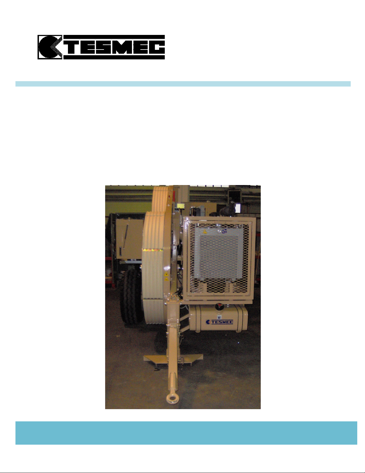
4.5 ELECTRONIC MULTIFUNCTION DAVICE PAGES
The electronic multifunction display shows 4 working pages:
1. METER COUNTER & SPEED PAGE
This page shows the speed and the meter
counter for each independent circuit
speed of capstan nr.1
meter counter of capstan nr.1
RPM diesel engine
hydraulic oil temperature
2. RPM & DIESEL ENGINE PAGE
This page shows the rpm of the diesel engine in
the center and 4 percentage check icons on the
edges:
diesel engine water cooling temperature
hydraulic oil temperature
diesel engine fuel level
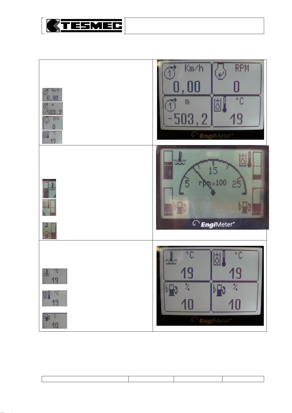
3. DIESEL ENGINE DATA PAGE
This page shows 4 percentage check icons of
diesel engine data:
.diesel engine water cooling
…...temperature
hydraulic oil temperature
diesel engine fuel level
PULLER-TENSIONER
Model: AFS303
Manual: MI-AFS303-320-00-GB
Date: 30.03.2015
Author: MC
Page: 14 of 32
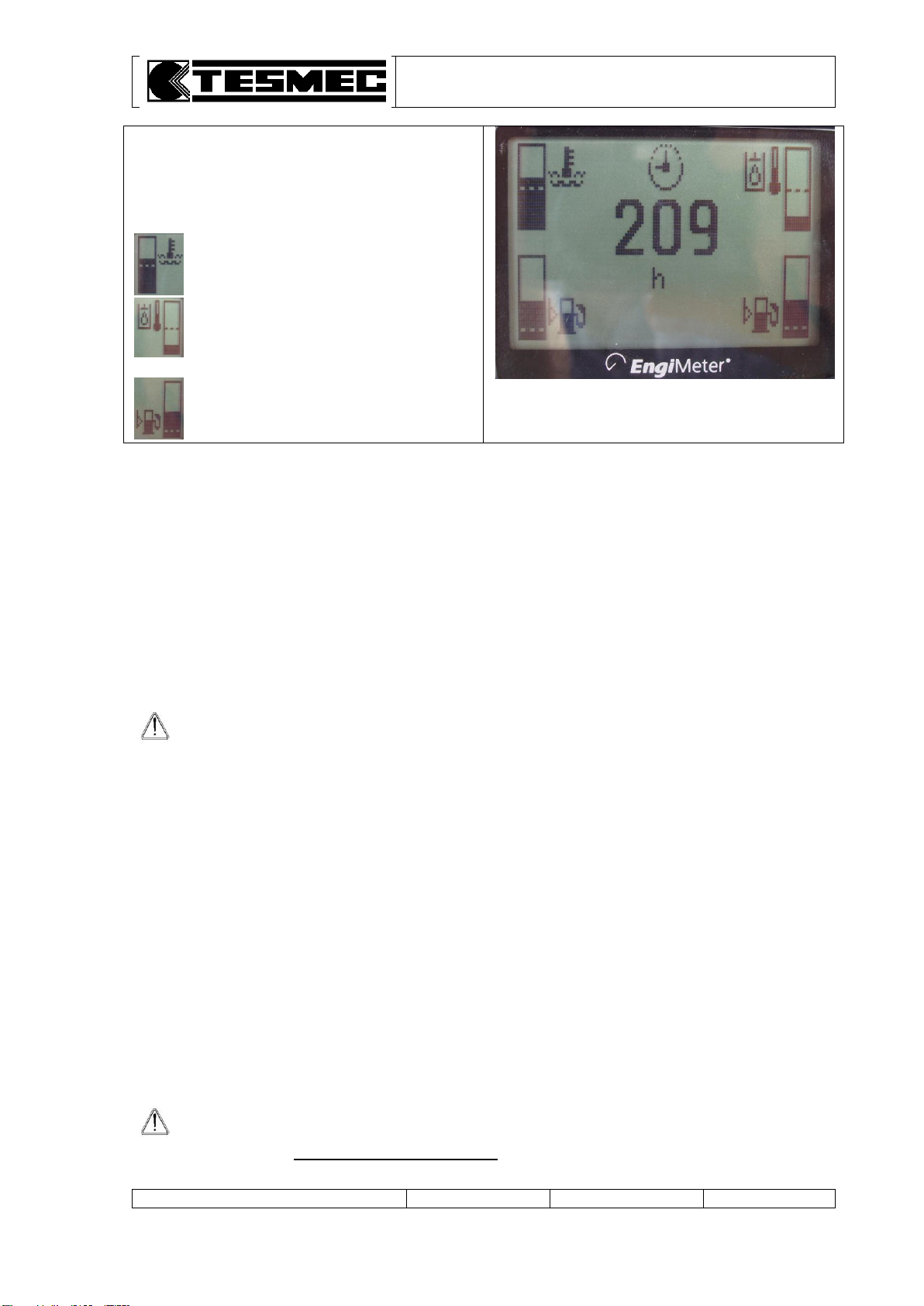
4. HOUR COUNTER PAGE
This page shows the working hour of the diesel
engine in the center and 4 percentage check
icons on the edges:
diesel engine water cooling temperature
hydraulic oil temperature
diesel engine fuel level
Switch from one page to the other one by using the up () or down () key.
4.6 STARTING OF THE MACHINE
a. Operate from the principal control panel (table 1).
b. Position to centre the control lever of the variable delivery pump.
c. Turn of one point the starting key (table 1, pos. 14).
d. Push and turn up to starting the starting key (table 1, pos. 14) and simultaneously keep the lever
(table 1, pos. 4) lowered.
The lever (table 1, pos. 4) must be lowered for a few seconds after the engine start-up.
e. Regulate the rpm with the accelerator (table 1, pos. 12).
f. Verify that the pressure indicate on the feeding manometer (table 1, pos. 7) is more than 20 bars
with minimum rpm; on the contrary stop the machine.
ATTENTION: when starting a cold machine, after heating the hydraulic oil as previously
described, begin stringing operations limiting the maximum working performances for
at least the first 15 minutes, that means to keep at half accelerator the Diesel rpm and
don’t exceed the 30% of the maximum stringing speed.
4.7 PULL CONTROL
The machine is equipped with two pull control devices for the control of the max. pull value on the line:
1. PULL LIMITING DEVICE that stops the machine when reaching the max. pull
2. PULL PROGRAMMING DEVICE that stops only the bull-wheels rotation keeping the diesel engine
turned-on when reaching the max. pull.
4.7.1 PULL LIMITING DEVICE SETTING
Completely turn right the knob (table 1, pos. 6).
With the suitable pawl, connected to the dynamometer move the red arrow in correspondence of
the max. pulling value that has not to be exceeded.
When the pre-set pull value is reached, the machine stops automatically and the diesel engine turns
off while the negative brakes automatically insert with the consequent stop of the bull-wheels
rotation. When the pull value is exceeded the warning light (table 1, pos. 20) on the control panel
turns on.
DANGER: when using a machine as tensioner, position the pull limiting device
(table 1, pos. 20) on the maximum scale, to avoid dangerous stopping.
This operation is absolutely indispensable when the machine “tensioner” works with a
puller without pull limiting device.

PULLER-TENSIONER
Model: AFS303
Manual: MI-AFS303-320-00-GB
Date: 30.03.2015
Author: MC
Page: 15 of 32
4.7.2 PULL PROGRAMMING DEVICE SETTING
ATTENTION: THE OPERATIONS TO SET THE PULL MUST BE CARRIED OUT WITH
STARTED DIESEL ENGINE BUT WHEN THE MACHINE IS TURNED OFF.
Start the diesel engine and set the engine at about 1600 rpm.
Move the selector (table 1, pos. 5) on position (rightwards).
Gently move towards (downwards) the lever (table 1, pos. 4).
Turn the knob (table 1, pos. 6) till on the manometer ring nut (table 1, pos. 1) can be read the pull
value that must not be exceeded.
ATTENTION: the red arrow of the pull limiting device has to be positioned at a higher
value than the one pre-set with the PULL PROGRAMMING DEVICE to avoid the machine
stop.
DANGER: when using a machine as tensioner, position the pull limiting device
on the maximum scale, to avoid dangerous stopping.
This operation is absolutely indispensable when the machine “tensioner” works with a
puller without pull limiting device.
Gently move the lever (table 1, pos. 4) to central position (neutral position).
Re-place the selector (table 1, pos. 5) on position (leftwards).
Once reached the set pull the bull-wheels automatically stop without the diesel engine turning off
with the consequent machine stop. The bull-wheels will remain stopped till when the cause which
tried to raise the pull over the imposed value is removed (line obstacles, increase of friction on the
pulleys, braking mistakes, etc.).
ATTENTION: after finishing the above mentioned operations and beginning stringing
operations, it is important not to touch the knob (table 1, pos. 6).
In fact, should the knob be rotated while the machine is stringing, this operation
cancels the previous carried out calibration and the systems set on the new values
congruent with new position of the knob.
Then, avoid this operation, using it only in emergency situations.
ATTENTION: before starting the work, check if the selector (table 1, pos. 5) is on
position . It is forbidden to move the selector (table 1, pos. 5) during working
operations because dangerous situations because the machine immediately stops may
happen.
ATTENTION: the dynamometer is calibrated with 3 scales: puller, tensioner and fine
braking. Read the desired values in function of the operations to be carried out (pulling
or tensioning).
PULLER-TENSIONER
Model: AFS303
Manual: MI-AFS303-320-00-GB
Date: 30.03.2015
Author: MC
Page: 16 of 32
4.8 CONNECTION MACHINE-HYDRAULIC HEAD OF THE REEL ELEVATOR OR REEL
WINDER
Each hydraulic head (or each reel-winder) has a connecting kit consisting of two pipes.
Each of these pipes has to be connected at the proper rapid connection taking care to connect them
properly (otherwise the installation will not work).
ATTENTION: it is important that, before connecting the rapid connections, the operator
has checked their cleanliness as the introduction of dirt into the hydraulic circuit can
create very serious damages.
ATTENTION: the rapid connections must be connected before to put in pressure the
circuit.
ATTENTION: the cocks must be opened when connecting the hydraulic heads (or reel
winders).
4.9 PULLING OPERATIONS
ATTENTION: before carrying out any operation it is necessary to verify if the selectors
(table 1, pos. 5 and 27 –optional) are turned towards leftwards .
a. Adjust the rpm of the diesel engine using the accelerator (table 1, pos. 12): puller –2600-rpm max.,
tensioner –1800/2000 rpm. The number of rpm can be read on the instrument on the panel
(table 1, pos. 17).
b. Adjust the feeding pressure of the hydraulic heads connected to the machine by the valve
(table 1, pos. 10) and read the correspondent value on the manometer (table 1, pos. 11).
When using the machine as puller, the pressure of the hydraulic heads will be from 60 bars (reels
with few turns) till a max. value of 120-130 bars (full reel).
Using the machine as tensioner, the pressure of the hydraulic heads can be set at 60-70 bars.
NOTE: the adjusting valve (table 3, pos. 10) regulates the pressure of the two circuits of
the reel elevators/reel winders, at the same time.
ATTENTION: it is important that this value is regulated at the minimum necessary value
in function of the operations that we must carried out (recovery or stringing).
In particular, during the final regulation of the bull-wheels, it is necessary to raise the
pressure when we recover and lower it when we string: on the contrary, due to the
mechanical and hydraulic efficiency, with the same set pressure we will have very
different pulls back.
c. Gently move the control lever of the pump (table 1, pos. 4) towards downwards .
Now the machine is ready to work: if the tension is higher than the set working value, the machine
operates as tensioner. If the tension is lower than the set working value, the machine operates as
puller. The machine is completely automatic, for this reason when setting a pulling value, the machine
works as puller or as tensioner following the motions of the opposite machine.
ATTENTION: the red arrow of the dynamometer (table 1, pos. 1) has to be positioned at
a value higher than the one set with the knob (table 1, pos. 6).
ATTENTION: after starting stringing operations, it is important not to turn the knob
(table 1, pos. 6). In fact, should the knob be rotated while the machine is stringing, this
operation cancels the previous carried out calibration and the systems set on the new
values congruent with new position of the knob.
d. To stop the bull-wheels rotation, move the lever towards centre position (table 1, pos. 4).

PULLER-TENSIONER
Model: AFS303
Manual: MI-AFS303-320-00-GB
Date: 30.03.2015
Author: MC
Page: 17 of 32
ATTENTION: do not quickly move the lever (table 1, pos. 4) towards centre position
because a fast connection of the negative brakes that might produce dangerous
damages to the disks mounted inside the brakes may happen.
During stringing operations, the strung meters can be read on the relevant indicator.
The indicator can be set to zero by pressing the push-button “RESET”.
During functioning operations, verify that:
a. the hydraulic oil temperature, shown on the thermometer (table 1, pos. 16), doesn’t exceed 80°C.
This is the maximum acceptable value for the hydraulic components in case the oils suggested by
Tesmec are used. If other kinds of oils are used, the maximum acceptable working temperature
depends on their characteristics in relation also to the viscosity limits imposed by the hydraulic
pumps and motors.
b. the warning lights of the electric clogging indicators mounted on the control board
(table 1, pos. 24 and 25) don’t switch on when the hydraulic oil reaches the working temperature.
However, it may happen that the lights indicate clogging even if it doesn’t occur (especially at very
low outside temperatures). In this case, see point e) paragraph 4.4 and wait for the lights to turn off
before making the bull-wheels run.
4.10 RELEASING THE ROPE
The rope or the conductor can be released, not under load, moving the lever (table 1, pos. 4) upwards
.
4.11 COMPRESSOR CONNECTION (OPTIONAL)
The machine has been studied to be connected to a Tesmec compressor.
a. Connect the rapid couplers (table 6, pos. 5 and 6).
b. Start the machine, turn the selector (table 1, pos. 27) towards right position and close the valve
(table 1, pos. 8).
c. Lower the lever (table 6, pos. 4) in "A" position.
d. Adjust the functioning pressure of the compressor using the valve (table 6, pos. 1).
The pressure can be read on the manometer (table 6, pos. 2).
Once ended the compressing operations, to use the machine act as follows:
a. turn the valve (table 6, pos. 1) and lower the pressure in the compressor.
b. lift the lever (table 6, pos. 4) in "B" position.
c. open the valve (table 1, pos. 8).
d. turn the selector (table 1, pos. 27) towards left position .
e. remove the rapid couplers (table 6, pos. 5 e 6).
ATTENTION: the connection of the rapid couplers has to be effectuated with the lever
(table 6, pos. 4) in "B" position to discharge the pressure in the hydraulic circuit.
If there is residual pressure in the hydraulic circuit, it is not possible to connect and
disconnect the rapid couplers.
Table of contents
Other Tesmec Industrial Equipment manuals


