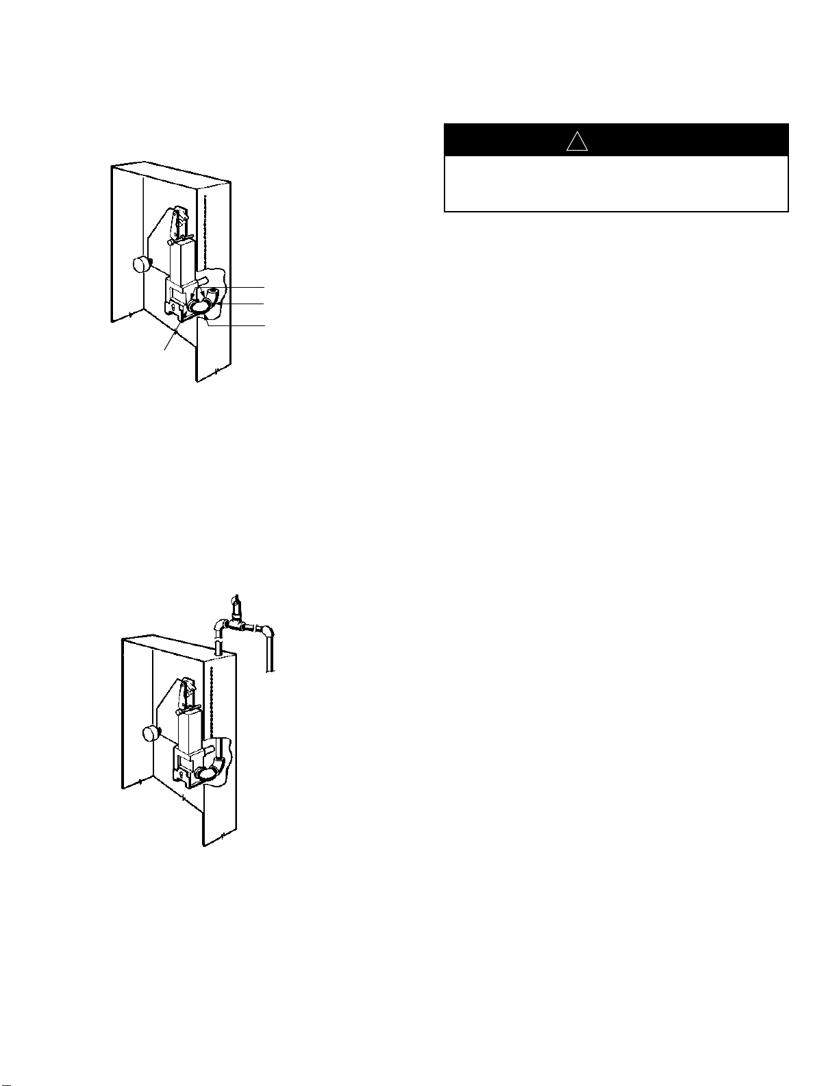
REMOTE MANUAL PULL STATION INSTALLATION
(CABLE TYPE) (Continued)
FIGURE 6
001800
WIRING THE “ANSUL AUTOMAN” II-C RELEASE
TheANSULAUTOMAN II-C is designed for use with the sep-
arately listed or approved fire detection and releasing control
unit which will initiate the electrical signal to operate the
release. Accordingly, conduit and wiring connections
between the release and the detection/alarm control system
should be made by or under the supervision of the detec-
tion/control system manufacturer’s technician.
Installation of Wiring
Aterminal strip is provided inside the ANSUL AUTOMAN
II-C enclosure for making field terminations. It is to be con-
nected to a nominal 12 VDC or 24 VDC releasing circuit. The
activation current is 450 mA at 12 VDC or 750 mA at 24 VDC
for approximately 55 milliseconds. The wiring diagram shown
in Figure 7 provides the details for making the field wiring
connections.
All interconnecting wiring to the solenoid is to be a minimum
of 18 AWG. All wiring should be done in accordance with the
National Electric Code and/or local codes and standards.
The circuit connections from the output of the Releasing
Control Unit are made to Terminals 4 and 8 of the ANSUL
AUTOMAN II-C release. The release is shipped with a
jumper (J2) installed across Terminals 4 and 5. If the releas-
ing control unit that is to be connected to the release requires
an in-line supervisory device to maintain proper circuit super-
vision, jumper J2should be removed and the appropriate in-
line supervisory device installed in its place. Refer to the
installation instructions from the manufacturer of the releas-
ing control unit for polarity requirements when installing an
in-line supervisory device.
Install the in-line supervisory device (SDxin Figure 7) across
terminals 4 and 5. Refer to the releasing control unit installa-
tion instructions for supervisory device requirements. If an in-
line supervisory device is not required, install jumper J2
across terminals 4 and 5.
Terminals 1 through 3 are provided for auxiliary device con-
nections. Auxiliary equipment is controlled through the action
of switch S1. Refer to the following ELECTRICAL DATA
SECTION for the contact ratings of S1.
Replace the protective cover over the terminal strip upon
completion of field wiring. Test the system by following the
procedures on the following pages.
ELECTRICAL DATA
Input Current: 750 mAat 24 VDC for 50 milliseconds
450 mAat 12 VDC for 50 milliseconds
Input Voltage: 12.5 – 30 VDC
Polarization: Polarization will result only by installation of
a polarized in-line supervisory device (SDx).
Observe polarity when connected to a
release circuit; terminal 4 positive, terminal 8
negative.
Contact Ratings: S1and S2contact ratings are 15A, 1/3
HP, 125 or 250 VAC resistive; 1/2A, 125
VDC; 1/4A, 250 VDC; 5A, 120 VAC
inductive
SOL1Coil Resistance: 28 ohms ± 10% at 77 °F (25 °C)
Operating Sequence
With solenoid cut-off switch (S2), in the normal position (the
release reset lever in the armed position), an electrical circuit
is formed between terminals 4 and 8. As the supervisory
release circuit of the control unit is activated, power is
applied between terminals 4 and 8 of TB1causing solenoid
SOL1to operate the ANSUL AUTOMAN II-C release. As the
release operates, S1and S2will change positions with S2
cutting power to the solenoid, which opens the release cir-
cuit. S1, being a condition switch, provides an isolated set of
form “C” contacts for auxiliary functions at terminals 1, 2 and
3 of TB1.
FIGURE 7
004302
INSTALLATION INSTRUCTIONS
UL R5998 6-16-95 Page 4
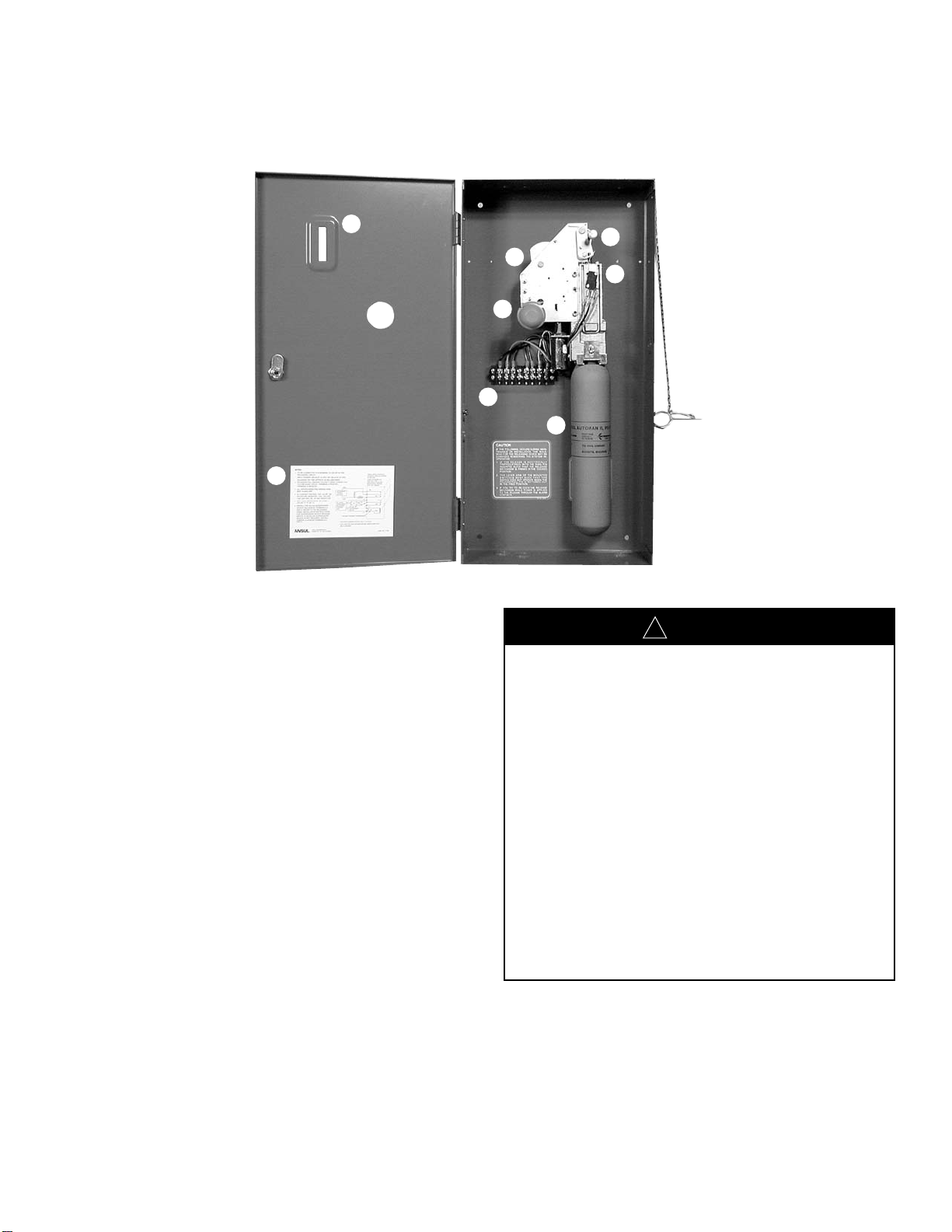
CAUTION
!
Do not install cartridge until all testing has been completed
and the system is ready to be armed as instructed on the
following pages.
1/2 IN.
(13 mm)
SEE
DETAIL “A”
DETAIL “A”
THESE SWITCH CONTACTS
TRANSFER UPON ACTUATION
OF RELEASE
“ANSULAUTOMAN” II-C
VOLTAGE TRANSIENT SUPPRESSOR
OR
IN-LINE
SUPERVISORY
DEVICE
UL LISTED
SUPERVISED
RELEASING
CONTROL
UNIT
TB1
J1
TZ1
J2
S1
(+)
(+)
(–)
(–)
S2
SDx
SOL1
NC
NC
ACCESSORY
POWER
SOURCE
*AUXILIARYALARMING DEVICES, SEE S1RATINGS
** FUEL SHUT-OFF VALVE, BLOWER MOTOR, DOOR CLOSER, ETC., SEE S1RATINGS
HIGH
LOW