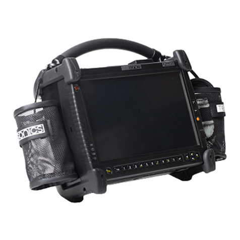
Tessonics RSWA Mounting instructions

RSWA
Resistance Spot Weld Analyzer
Software Manual
1 1
1 1

2 2
2 2

Tessonics Corporation has made every effort to ensure the accuracy and completeness
of this document; however, because ongoing efforts are made to continually improve
the capabilities of our products, we cannot guarantee the accuracy of the contents of
this document. We disclaim liability for errors, omissions, or future changes herein.
Tessonics and the Tessonics logo are trademarks of Tessonics Corporation.
Fujitsu and the Fujitsu logo are registered trademarks of Fujitsu Limited.
Intel and Pentium are registered trademarks of Intel Corporation.
Microso is a registered trademark of Microso Corporation. Windows 2000 and Win-
dows XP are trademarks of Microso Corporation.
All other trademarks mentioned herein are the property of their respective owners.
Copyright 2007–2009 Tessonics Corporation. All rights reserved. No part of this doc-
ument may be copied, reproduced, or translated, without the prior written consent of
Tessonics Corporation.
3 3
3 3

4 4
4 4

i
Contents
1 Common Software Features 1
1.1 On-Screen Keyboard 1
1.2 Log In Prompt 2
2 Launcher 3
2.1 Main Window 3
2.2 Logging In and Out 3
2.3 Turning Off 4
2.4 Switching Between Applications 5
2.5 Accessing a USB Drive 5
2.6 Launcher Tabs 6
2.6.1 Settings Tab 6
3 Array Explorer 9
3.1 Main Window and Terminology 9
3.2 Button Area 11
3.3 C-Scan Area 12
3.4 A-Scan Area 13
3.5 Indicator Area 14
3.6 Measurement History Area 15
3.7 Status Bar 15
3.8 Settings 15
3.8.1 Continuous Mode Panel 15
3.8.2 Algorithm Panel 15
3.8.3 Hardware Panel 17
3.8.4 Waveform Panel 18
3.8.5 Adjust Signal 18
3.8.6 User Interface 19
3.9 Inspection and Information Area 20
3.10 Inspections 21
3.10.1 Custom Inspection Mode 21
3.10.2 Part Inspection Mode 23
3.10.3 Opening Inspections 26
3.11 Command Line Switches 27
Index 29
5 5
5 5

ii RSWA Software Manual
6 6
6 6

1
Chapter 1
Common Software Features
is section describes features common to all soware components.
1.1 On-Screen Keyboard
ere are times during RSWA usage when you need to type text: entering passwords, le
names, etc. Unfortunately, the RSWA unit does not have room for a built-in keyboard. In-
stead, when typing is necessary, you will see a virtual on-screen keyboard.
is keyboard allows typing using the touch screen.
Figure 1.1
Note: e layout of the keyboard depends on the currently active language.
To switch to numeric keypad and back, use button:
Figure 1.2
7 7
7 7

2RSWA Software Manual
is virtual keyboard is capable of supporting more than one keyboard layout in different
languages. To manage keyboard layouts, go to Control Panel → Regional and Language
Options → Languages.
1.2 Log In Prompt
When someone tries to run a protected Tessonics application they will get the log in prompt
shown in Figure 1.3. Only the users who have permission to access to the protected appli-
cation will be shown in the list. To log in, click your user name. If your user has a password
assigned, then you will be prompted to enter the password.
Figure 1.3 Login prompt
Each user has an associated icon to help them nd their name when logging in. It’s best
practice to assign each user a different icon. See the User Manager chapter in the RSWA
Administrator Manual for information on how to create and manage users.
8 8
8 8

3
Chapter 2
Launcher
e Launcher allows the user to start Tessonics applications, and normally loads when the
RSWA starts up and replaces the Windows desktop. e Launcher was designed and built
for touchscreens, and is more convenient than a regular windows desktop. It also limits and
controls user access to critical system settings and programs.
2.1 Main Window
Figure 2.1 shows the main Launcher screen. For each application that is available, a button
is placed in the center (gray) section of the screen. Applications can be started by simply
pushing the corresponding button.
Figure 2.1 Main Launcher window
2.2 Logging In and Out
Certain Windows and Tessonics applications have been protected and require users to have
special privileges in order to use them. Some protected applications will allow you to log in
(for that application only) when you try to start them and others will not start at all unless
you are already logged in.
9 9
9 9

4RSWA Software Manual
Clicking the Log In button, shown in Figure 2.2, will bring up the Login prompt discussed
in Section 1.2, Log In Prompt. When you log in this way your user information is retained,
thus allowing you to start multiple protected applications without having to repeatedly log
in. is is the recommended way to use the RSWA.
Figure 2.2 Logging in and out of Launcher
Aer you log in, the label on top of the button shows the name of the current user. e
button caption changes to Log Out and now you can use it to log out of the system.
Note: If the computer goes to standby while you are logged in, the system will automati-
cally log you out to prevent unauthorized access by different users.
2.3 Turning Off
Clicking the Turn Off button will provide you with a list that allows you to Hibernate, Shut
Down, or Restart the computer; see Figure 2.3. Shutdown puts the system into off mode,
and Hibernate puts the system in Save-to-Disk mode. Restart simply reboots the system.
Figure 2.3 Turning system off
10 10
10 10

Chapter 2 Launcher Accessing a USB Drive 5
2.4 Switching Between Applications
When one or more applications are running the Switch button in Figure 2.4 becomes active.
Clicking this button provides a list of all the running applications and allows you select which
one you want to see or use. If an application is minimized this is the only way to bring it
back into view.
Figure 2.4 Switching between applications
2.5 Accessing a USB Drive
To access the USB port, open the aps on the right hand side of the so case. e location
of the USB port on the CPU unit is shown in Figure ??.
You can use any standard USB drive to transfer les to and from the unit.
When a USB drive is plugged in, the button in Figure 2.5 becomes visible. Clicking this
button provides the following options:
Figure 2.5 USB menu
Browse USB Drive
Opens Windows Explorer to work with les stored on the USB drive. is option is
available only to users with Admin permissions.
Safely Remove USB Drive
Select this option before unplugging the USB drive from the USB port.
Soware Updates
Selecting this option presents another list containing all the soware that can be
updated or installed from the USB drive. is option is only shown if there exists
11 11
11 11

6RSWA Software Manual
some updates on the USB drive. See the RSWA Administrator’s Guide for more
information.
Warning: Always use the Safely Remove USB Drive option before unplugging the drive,
especially if you’ve modied les on it. Otherwise you risk loosing your data.
2.6 Launcher Tabs
e Launcher Tabs, shown in Figure 2.6, determine what is shown in the center (gray) sec-
tion of the Main Window, shown in Figure 2.1. e Applications, Utilities, and Admin tabs
show different groups of applications that can be started by the user; the Admin tab is re-
stricted to users with admin permissions. e Settings tab is also restricted to users with
admin permissions and it is discussed in Section 2.6.1, Settings Tab. e Info tab provides
some information about the RSWA and contact information for Tessonics.
Figure 2.6 Launcher tabs
2.6.1 Settings Tab
e Settings Tab is available only to users with Admin permissions. It contains the following
sections:
• Control Panel
• Launcher
• Applications
• Utilities
• Admin
• Deleted Items
12 12
12 12

Chapter 2 Launcher Launcher Tabs 7
Control Panel Section
Provides access to the standard Windows Control Panel.
Launcher Section
Allows you to choose which desktop application will be activated when Windows starts; the
Windows Desktop or the RSWA Launcher. Unless you have a good reason for doing so,
it is highly recommended that the RSWA Launcher be used. Using the Launcher limits a
user’s access to the computer and helps prevent them from accidentally causing soware
problems. e Launcher Section also allows you to set the default language that is used
with the Launcher and applications started from within the Launcher. e default language
selected in this section is completely independent of the default language used by Windows
and as a result will not have any affect if the Windows Desktop is used.
Figure 2.7 Launcher settings
13 13
13 13

8RSWA Software Manual
Applications, Utilities, and Admin Sections
Allows you to add and remove programs from the Application, Utilities and Admin tabs in
the main Launcher window. All three sections have similar appearance (see Figure 2.8).
Figure 2.8 Utilities settings
Push the Add button to add a new item to the list. You will need to choose the name of the
item, path of the executable le, command line options and an icon.
Push the Modify button to rename an item, change it’s icon or edit other options.
Push the Remove button to remove an item from the list. If you remove an item accidentally,
you can restore it from the Deleted Items section.
Deleted Items
Allows restoring any programs that were deleted from the Applications, Utilities or Admin
tabs.
Select a deleted item from the list and click Restore to move it back to one of the tabs, or
click Purge to delete the item permanently.
14 14
14 14

9
Chapter 3
Array Explorer
is chapter explains how to use Array Explorer to analyze spot welds. It is important to note
upfront that the operation of Array Explorer depends on your permission level and whether
or not you are working on a inspection. Currently, Array Explorer has two permission lev-
els: standard and advanced. Some features are only available to advanced users, and some
critical settings can only be modied by the Admin user. ese features will be noted in the
explanations that follow. Inspections are explained in Section 3.10, Inspections, which are
the only way to save the RSWA’s measurements.
3.1 Main Window and Terminology
e Main window consists of seven areas, which are explained in the following sections:
Button area C-scan area
A-scan area
Measurement history
Indicator Inspection and information area
Status bar
Figure 3.1 Main Array Explorer Window
15 15
15 15

10 RSWA Software Manual
Terminology used in this chapter:
Inspection
A group of weld measurements that are saved together.
Part
A manufactured object that has spot-welds.
Inspection Order
e order in which spot-welds on a Part are to be measured.
16 16
16 16

Chapter 3 Array Explorer Button Area 11
3.2 Button Area
Setup
Setup the unit for measuring welds on a specic metal stack.
Get
Takes a single measurement. (Push and hold to enter continuous
mode; see Section 3.8.1, Continuous Mode Panel.)
e next three buttons are used with inspections. (See Section 3.10,
Inspections)
Pass
Clicking this button passes the current weld in the weld list. If a
measurement hasn’t been performed or the pass button is held
down, a pop-up list of reasons for passing the weld will appear.
Fail
Clicking this button fails the current weld in the weld list. You
must select a reason for failing a weld from the pop-up list that
appears.
Next Unit (In Part Inspection mode)
Shown only for Part Inspections, this button replaces the New
Weld button. Pressing it will start a new inspection using the
same part you were working on.
New Weld (In Custom Inspection mode)
Shown only for a Custom Inspection, this button adds a weld to
the list of measured welds.
e next two buttons allow starting, saving, and opening inspections (see
Section 3.10, Inspections):
New Inspection/End Inspection
Starts new inspection. Once an inspection is started, this button
changes to End Inspection.
Open Inspection
Opens a previously stored inspection (see Section 3.10.3, Opening
Inspections).
Settings
Allows changing various application settings (see Section 3.8,
Settings).
17 17
17 17

12 RSWA Software Manual
3.3 C-Scan Area
is area shows the image that is created from the collected measurement data. e green
areas have fusion and the red areas do not have fusion.
Figure 3.2 C-scan area
Dotted Circle
Shows the automatic estimation of weld nugget location and diameter. If the esti-
mation is off it can be manually adjusted by clicking the hand icon. Dragging the
edge of the circle will resize it and dragging the interior of the circle will reposition
it. e dots turn blue when in manual mode. Clicking the hand a second time will
undo any manual modications.
Small Background Squares
Represent the transducer’s elements. e currently selected elements waveform will
be shown in A-scan area (see Section 3.4, A-Scan Area).
Spinning Wheel
Shows minimum/nominal size of the weld.
Indentation Button
Sets acceptable indentation range for the weld being measured.
Hand Button
Switches to manual circle sizing and back.
18 18
18 18

Chapter 3 Array Explorer A-Scan Area 13
3.4 A-Scan Area
e A-Scan area shows waveforms (A-Scans) for the individual elements in the transducer’s
matrix.
Figure 3.3 A-scan area
You can choose which one out of the 52 matrix elements is displayed by making a selection
in the C-scan area (see Section 3.3, C-Scan Area).
White Curve
Shows the A-scan for the currently selected element.
Shadow in Background
Shows the composed A-scans from all the elements.
Number Boxes
Position of front-wall and back-wall reections.
Green Vertical Lines
Gates showing the range for C-scan acquisition. ese gates are set automatically
when you press the Setup button. To adjust them manually, push and hold the touch
screen inside the A-scan area.
19 19
19 19

14 RSWA Software Manual
Additional options are available through a drop down menu:
Figure 3.4 A-scan menu
Display Mode
Used to change how a-scans are displayed. e default value is Bipolar.
Ruler Units
Used to change the units used for the a-scan ruler. e default is Depth.
3T Mid. ickness
Used to set the thickness of the middle plate when performing 3T inspections. Make
sure this to off when performing a 2T inspection.
Processed A-Scans
Use this option to see a-scans with signal processing (default)
Raw A-Scans
Use this option to see a-scans without signal processing.
3.5 Indicator Area
Figure 3.5 Indicator area
e indicator area shows the estimations for the current weld nugget size and indentation.
is area will also indicate errors involving the ultrasonic hardware. shows errors involving
the ultrasonic hardware.
20 20
20 20
Other manuals for RSWA
1
Table of contents
Other Tessonics Measuring Instrument manuals
Popular Measuring Instrument manuals by other brands

Siemens
Siemens SENTRON 7KT PAC1200 System manual
Spectrum Technologies
Spectrum Technologies Field Scout 2265FS manual
LaserLiner
LaserLiner AirCheck Clima instructions
JONARD TOOLS
JONARD TOOLS PON-55 instruction manual
ACS contsys
ACS contsys DAL-311x0x0S operating instructions
Dinel
Dinel ULM-55N instructions
