Tessonics RSWA User manual

1 1
1 1
RSWA
Resistance Spot Weld Analyzer
User’s Guide
2008-02-05

2 2
2 2

3 3
3 3
Tessonics Corporation has made every effort to ensure the accuracy and completeness
of this document; however, because ongoing efforts are made to continually improve
the capabilities of our products, we cannot guarantee the accuracy of the contents of
this document. We disclaim liability for errors, omissions, or future changes herein.
Tessonics and the Tessonics logo are trademarks of Tessonics Corporation.
Fujitsu and the Fujitsu logo are registered trademarks of Fujitsu Limited.
Intel and Pentium are registered trademarks of Intel Corporation.
Microso is a registered trademark of Microso Corporation. Windows 2000 and Win-
dows XP are trademarks of Microso Corporation.
All other trademarks mentioned herein are the property of their respective owners.
Copyright 2007 – Tessonics Corporation. All rights reserved. No part of this document
may be copied, reproduced, or translated, without the prior written consent of Tessonics
Corporation.

4 4
4 4

5 5
5 5
Contents
1 Getting Started 1
1.1 Damage in Transit 1
1.2 Setting Up 1
2 Hardware 3
2.1 Overview 3
2.2 Probe 4
2.2.1 Usage 4
2.2.2 Cleaning and Maintenance 4
2.3 CPU Unit 5
2.3.1 Features 5
2.3.2 Status Indicators 6
2.3.3 System States 7
2.3.4 Screen Protector 8
2.3.5 Storing 9
2.3.6 Using the Hotpad 9
2.3.7 Using Hovering Mode 10
2.4 DSP Board 11
2.5 External Battery 12
2.5.1 PowerPad 80 12
2.5.2 Universal Battery 13
2.6 Charger/AC Adapter 14
2.7 So Case 14
3 Common Software Features 15
3.1 On-Screen Keyboard 15
3.2 Login Prompt 17
4 Launcher 19
4.1 Main Window 20
4.2 Logging In and Out 20
4.3 Turning Off 21
4.4 Switching Between Applications 22

6 6
6 6
ii RSWA User’s Guide
4.5 Accessing a USB Drive 22
4.6 Launcher Tabs 23
4.6.1 Settings Tab 24
5 Array Explorer 27
5.1 Main Window and Terminology 28
5.2 Button Area 29
5.3 C-Scan Area 30
5.4 A-Scan Area 31
5.5 Measurement History 32
5.6 Settings (Standard) 32
5.6.1 Cont. Mode 32
5.6.2 User Interface 32
5.7 Settings (Advanced Mode) 33
5.7.1 Algorithm 33
5.7.2 Hardware 33
5.8 Settings (Admin Mode) 34
5.8.1 Waveform 34
5.8.2 Adjust Signal 34
5.9 Information 34
5.10 Inspections 35
5.10.1 Custom Inspection 35
5.10.2 Part Inspection 38
5.10.3 Opening Inspections 40
A Specifications 43
Index 45

7 7
7 7
Chapter 1
Getting Started
e Tessonics Resistance Spot Weld Analyzer (RSWA) has been designed and manufactured
as a high quality instrument. Under normal working conditions the RSWA will provide long,
trouble-free service.
1.1 Damage in Transit
Inspect the unit thoroughly and immediately upon receipt, for evidence of external or in-
ternal damage that may have occurred during shipment. Immediately notify the carrier
making the delivery of any damage, since the carrier is usually liable for damage in ship-
ment. Preserve packing materials, waybills, and other shipping documentation in order to
claim any damages. Aer notifying the carrier, contact Tessonics to receive assistance in
the damage claims, and provide replacement equipment, if necessary. Please note that your
shipping container is re-usable and may be used in the future when returning the unit for
recalibration or repair.
1.2 Setting Up
Check the list of supplied items. Verify that you have received all items listed on the RSWA
Packing List. If anything is missing, please contact Tessonics Sales and Service office.
Please check the battery charge gage aer receiving it. Refer to Section 2.5 on page 12 on
how to interpret the batteries fuel gage indicator.
Note: e external battery is shipped DISCONNECTED
Open the battery pocket cover of the so case and connect the battery connector to the
internal wiring cord connector. Connect the A/C adapter to the external battery and charge
the battery for at least 4 hours before using it for the first time.

8 8
8 8
2RSWA User’s Guide

9 9
9 9
Chapter 2
Hardware
2.1 Overview
e Resistance Spot Weld Analyzer consists of several parts (Figure 2.1). e base unit con-
sists of a Windows-based tablet PC with an attached DSP board and installed soware. e
probe has a 52-element matrix transducer which connects to the DSP board. An external
battery provides up to 6 hours of run time when disconnected from a power source. A
charger/AC adapter provides power for simultaneous device operation and battery charg-
ing. A so case holds all these components together and provides protection against shock
and mechanical damage in an industrial environment.
Tablet PC
DSP board
Probe
External battery
Soft case
Figure 2.1 RSWA Hardware Components.
10 10
10 10
4RSWA User’s Guide
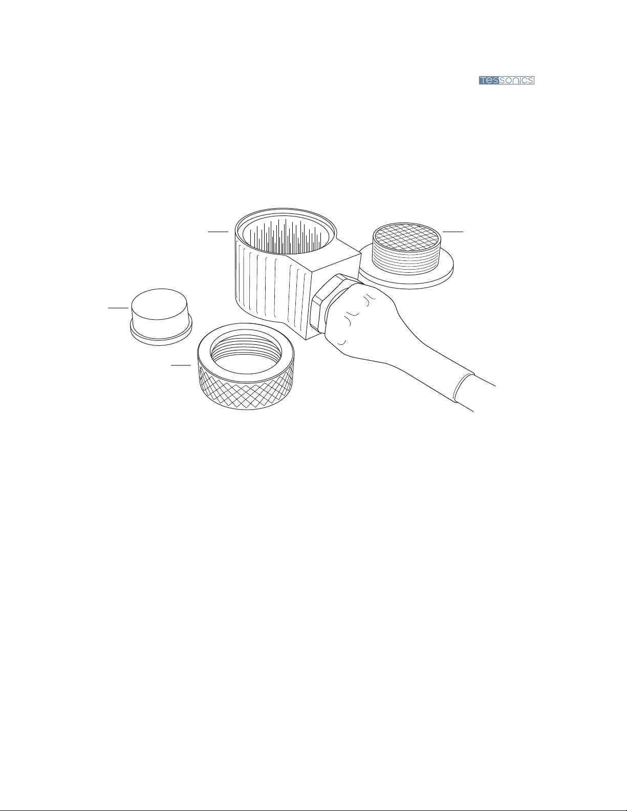
2.2 Probe
e probe consists of a multiple coax cable and an ultrasonic transducer. is is the most
critical part of an RSWA. A malfunctioning or damaged transducer, as well as coax cable,
will make measurements inaccurate or non-existent. Figure 2.2 shows the major parts of the
probe.
Matrix transducer
Housing
Delay line
Coupler
Figure 2.2 Probe components.
2.2.1 Usage
e front face of the transducer is very thin and fragile. Check that there is no dust, grease,
or any other foreign particles between the front face of the probe and the delay line before
mounting the delay. e delay and the coupler are the only replaceable parts on the probe.
Please do not try to disassemble the protective case, take out the matrix transducer, or detach
the cable from the protective case as this will damage the probe beyond repair.
2.2.2 Cleaning and Maintenance
• Clean the front face and the thread of the transducer. If possible, use isopropyl alcohol,
dry using an air jet
• Clean the face of the delay which will be in contact with the front face of the transducer
and the collar using the same technique, dry with an air jet
• For operation, a very thin layer of a standard ultrasonic gel should be applied between
the transducer front face and the delay to provide sufficient acoustical contact

11 11
11 11
Chapter 2 Hardware CPU Unit 5
• Make sure the gel is clean and there are no air bubbles in it
• During storage or transportation, the front face of the transducer must be protected with
the delay or with a protection cap
• When storing the transducer for long periods of time (longer than a month), make sure
there is no gel le on the surface of the transducer
• Under normal operating conditions, the gel layer should be replaced each month; In a
warm and dry environment the gel should be replaced more oen
Warning: When re-assembling the transducer, ensure the delay line is face up before
attaching the coupler
2.3 CPU Unit
e CPU unit is a fully functional computer (a Tablet PC) which runs the RSWA soware.
2.3.1 Features
Microphone
System status LEDs
Speaker
Headphone jack
Microphone jack
Suspend/resume button
Hotpad area
Pen holder
Figure 2.3 Tablet PC parts (front view).
12 12
12 12
6RSWA User’s Guide
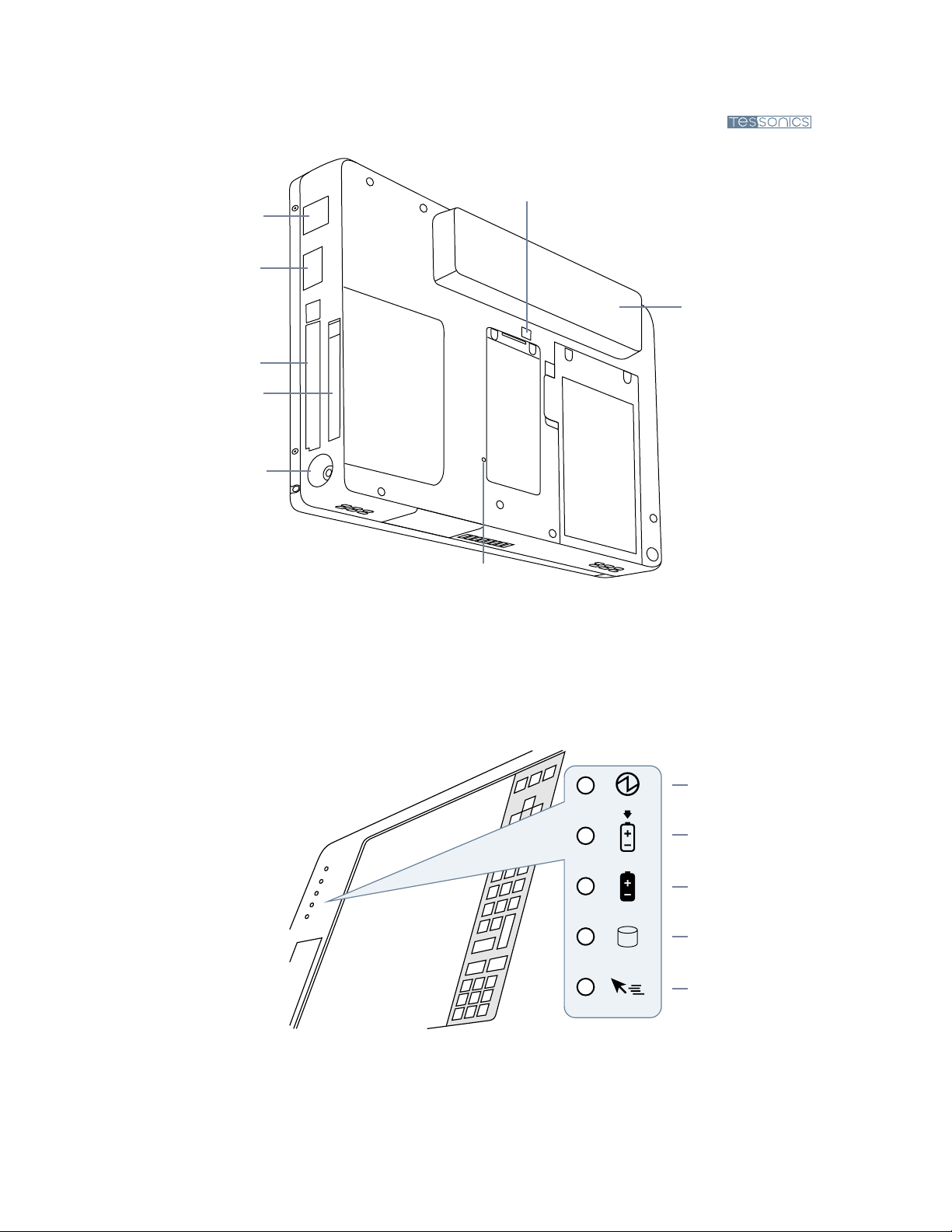
Modem port
USB port
PCMCIA slot
Compact flash slot
DC power connector
Internal Battery release switch
Internal Battery pack
Reset button
Figure 2.4 Tablet PC parts (rear view).
2.3.2 Status Indicators
Status indicators show the status of system functions such as system power and internal
battery charge level. e location of these indicators is shown in Figure 2.5
Power
Charge/DC in
Internal Battery
HDD access
Hovering
Figure 2.5 Status indicators.
13 13
13 13
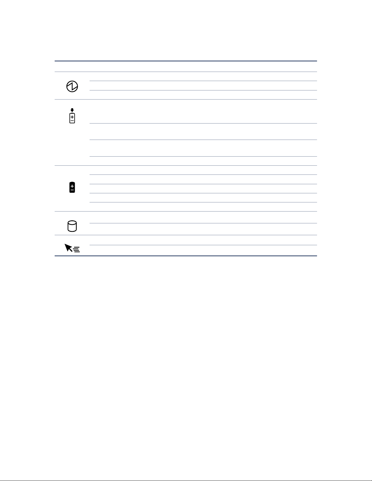
Chapter 2 Hardware CPU Unit 7
Icon LED State Remarks
Power Green (continuous) On State or Idle Mode
Green (blinking) Suspend-to-RAM State
Off Off State or Save-to-Disk State
Charge Green •AC adapter and interal battery are available and system is not
charging (internal battery fully charged).
•AC adapter is available but internal battery is not present.
Amber (continuous) AC adapter and internal battery are available and system is
charging.
Amber (blinking) AC adapter and internal battery are available and waiting to
charge (internal battery is out of thermal range).
Off AC adapter is not available.
Internal
Battery
Green Internal battery charge is 100% – 50%
Amber Internal battery charge is 49% – 13%
Red Internal battery charge is 12% – 0%
Red (blinking fast) ere is an internal battery error.
Off Internal battery is not installed.
HDD Access Green Displayed when hard disk drive is accessed.
Off Hard disk drive is not being accessed.
Hovering Green Hovering mode is enabled.
Off Hovering mode is disabled.
2.3.3 System States
On Mode – e system is running and the display screen is on.
Idle Mode – Some system functions are regulated or turned off to conserve power. e
display screen may be turned off. e system returns to the On state when pen activity
or other input is detected.
Suspend-to-RAM Mode – System operation is suspended. Most system functions are turned
off to conserve power. Power to memory is on, maintaining data in programs that were
running before system operation was suspended. e system does not respond to the
pen or other input when in Suspend-to-RAM mode. Refer to the “Resuming System
Operation” section later in this chapter for information on returning the system to the
On mode.
Save-to-Disk Mode – System operation is suspended. All system functions are turned off
to conserve power. Active data in programs that were running before suspending system

14 14
14 14
8RSWA User’s Guide
operation is stored on the hard disk drive. e system does not respond to the pen or
other input. Refer to the “Resuming System Operation” section later in this chapter for
information on returning the system to the On mode.
Off Mode – All system functions are turned off to conserve power. e system does not
respond to the pen or other input. e system boots at the next system power-on.
Note: e system consumes the same amount of power whether it is in Save-to-Disk
mode or Off mode.
Your system can be configured to enter some of these states automatically aer a period of
inactivity to conserve battery power.
2.3.4 Screen Protector
Using a screen protector will help insure that the screen remains as clear as possible. When
installed, the screen protector becomes a durable, replaceable surface that protects the dis-
play from abrasion.
Note: e tablet PC is not waterproof. Do not pour liquids on the system or wash it with
a wet cloth.
To install a new screen protector:
1. If a screen protector is already installed on the display screen, remove it before installing
the new screen protector. e screen protector is held onto the display screen surface by
a thin strip of adhesive around the edges. A notch in one corner of the screen protector
allows you to slide your fingernail under the screen protector for easy removal.
2. Clean the display by wiping the screen surface gently using a so cotton cloth dampened
with denatured alcohol. Ensure that all residues have been removed from the screen
before applying a new screen protector.
3. Remove the protective coating from the adhesive side of the screen protector first. Apply
the screen protector to the display screen surface. When doing so, orient the screen
protector with the adhesive side of the screen protector facing the display screen and the
notched corner of the screen protector toward the lower le corner of the display screen.
4. Apply pressure to the screen protector with your finger using a continuous wiping mo-
tion along the edges. e adhesive sets completely within 48 hours. To ensure a good

15 15
15 15
Chapter 2 Hardware CPU Unit 9
seal between the screen protector and the display, do not li the screen protector from
the display once it has been applied.
5. Remove the protective plastic cover from the face of the screen protector.
6. Clean any residue remaining on the screen protector by wiping gently with a so cotton
cloth dampened with denatured alcohol. Wipe the screen protector with a so dry cloth
to remove any low-tack adhesive.
2.3.5 Storing
Store the equipment in the Off state with a fully charged external battery installed. e exter-
nal battery always provides power to some system components even when the system is in
the Off state. If the system is stored with the external battery removed, these components are
powered by the system’s internal battery. e internal battery is not designed for extended
use and will discharge in a short period of time; this could result in damage to the internal
battery. You can store the equipment in the Off state for about 30 days with a fully charged
external battery installed. Aer this period, the external battery pack should be recharged
or replaced with a charged external battery.
2.3.6 Using the Hotpad
e Hotpad area consists of several touch screen “keys” on the right side of the system display
that you can use to change several settings. e hotpad allows you to:
• Adjust the display and speaker settings
• Invoke right mouse button
• Invoke hovering capability
• Use as a numeric pad
• Use as a NumLock key
To use a hotpad key, tap directly on it with the pen. You can also press and hold the pen tip
against the Volume and Brightness hotpad keys to automatically repeat the previous hotpad
function. e location of each hotpad key is shown in the table below.

16 16
16 16
10 RSWA User’s Guide
Icon Name Description
Escape Functions the same as the Esc key on a typical
keyboard.
Display Each time the Display Device hotpad key is tapped,
the display unit is switched (in the following order):
LCD – CRT – both LCD and CRT, back to LCD.
NumLock Acts in the same way as the NumLock on the
keyboard. (Default is Off.)
Cursor Control Acts in the same way as the cursor keys on a
keyboard.
Numeric Keypad Acts in the same way as the numeric keypad on a
keyboard. (Note: “BS” signifies “Backspace”)
Right Mouse Button Switches the pen function from le mouse button
to right mouse button emulation for a single mouse
event aer tapping the hotpad.
Pen Hovering Switches the hovering mode on or off. roughout
the hovering mode, the hovering status indicator is
lit green.
Speaker Volume Decrease/Mute/Increase the speaker volume.
Brightness Control Changes the luminance of the display backlight.
Changes in brightness level can be monitored with
the on-screen indicator.
2.3.7 Using Hovering Mode
Selecting the Pen Hovering icon on the Stylistic LT P-600 keypad provides the user with
better cursor control. When the hovering option is enabled, the cursor can be positioned
over an icon without activating it. is is useful when you are performing procedures that

17 17
17 17
Chapter 2 Hardware DSP Board 11
require accurate cursor positioning, such as when simulating a mouse rollover, selecting a
small icon, or beginning a paint session.
• To enable hovering, tap the Pen Hovering icon on the keypad. e Hovering system
status indicator light illuminates green when hovering is selected.
• To disable hovering, tap the Pen Hovering icon again. e Hovering system indicator
light is off when hovering is not selected.
2.4 DSP Board
e DSP (Digital Signal Processing) Board connects the transducer with the computer. e
major parts of the board are:
DSP – Handles communications with the computer, controls all the activity of various
components on the board, provides certain stages in signal processing.
Pulser – Sends a short electrical pulse to the transducer.
Receiver – Receives electrical signals coming back from the transducer.
Multiplexer – Redirects signals from pulser to a particular element in the transducer.
ADC – Analog-to-digital converter – Converts electrical signals into a digital form.

18 18
18 18
12 RSWA User’s Guide
2.5 External Battery
In addition to the battery that comes together with the tablet PC, an RSWA is equipped with
the second external battery . is additional battery pack provides power for the DSP board
and simultaneously charges and powers the tablet PC.
RSWA can be equipped with one of the following battery types (see Figure 2.6):
• PowerPad 80 (shipped with older units)
• Universal battery (shipped with newer units)
PowerPad 80 Universal battery
Figure 2.6 External batteries
2.5.1 PowerPad 80
is external battery uses a comprehensive fuel gauge system to indicate its state of charge.
e fuel gauge, which consists of 3 green lights, 1 yellow light and 1 red light, will normally
be lit and will turn off automatically when the battery is not in use.
Under abnormal operating conditions, such as extreme temperatures, the battery will not
charge or discharge. Under these conditions the light panel will indicate 1 red light and 1
green light.
While the battery is charging, the fuel gauge lights will blink every 7 seconds until the battery
is fully charged, at which time the fuel gauge lights will remain lit. e lights that are “ON”
will indicate the state of charge at that time.
While the fuel gauge provides a relatively accurate state of charge during discharge, it more
accurately shows the true state of charge when idle. It is therefore normal for the battery to
alter its state of charge aer it has been idle for more than an hour.
Note: When not in use for a month or more, fully charge the battery prior to storing.

19 19
19 19
Chapter 2 Hardware External Battery 13
80 to 100% 50 to 80% 30 to 50% 20 to 30% 10 to 20% less than 10% fully discharged non operational
Figure 2.7 PowerPad 80 fuel gauge
2.5.2 Universal Battery
e universal battery has a DC out voltage switch at the back (Figure 2.8).
Note: is switch must be set to the 16V position (knob toward the center of the battery).
e power meter is activated by pressing Test button. e number of LED lights indicates
the power level of the battery pack (Figure 2.8).
Testing button
100%
75%
50%
25%
Low battery alarm
Figure 2.8 Universal battery DC out voltage switch (left) and power meter (right).

20 20
20 20
14 RSWA User’s Guide
2.6 Charger/AC Adapter
e Universal AC adapter transforms power line voltage into DC voltage which is used for
charging the external battery and/or simultaneous operation of the RSWA.
An input range 100–240 V at frequencies 50–60 Hz makes it possible to use the adapter in
most countries around the world. It is strongly recommended to use the supplied power
cord, as its plug determines the type of suitable power line.
e output cord connects to the charging input of the external battery. If you have a newer
Universal Battery, you can also bypass the external battery and plug the adapter directly into
the RSWA unit. (Useful if the external battery ever becomes faulty and you want to continue
running the RSWA).
Note: Keep AC adapter clean and away from spilled liquids and shocks. If there is any
type of visible damage to the adapter case or power cord, the item should be replaced.
Warning: Tessonics has no responsibility for damage caused by use of unauthorized
power adapters or by connecting the power adapter to improper power lines.
2.7 Soft Case
A so case holds the whole device together and protects it from shock and mechanical dam-
age. Additional features are pockets for gel bottles and accessories. e rear part of the case
flips out and can be used as a rest for convenient positioning of the unit.
Other manuals for RSWA
1
Table of contents
Other Tessonics Measuring Instrument manuals


Popular Measuring Instrument manuals by other brands


PCB Piezotronics
PCB Piezotronics 354M56 Installation and operating manual

Dewetron
Dewetron DEWE-30-32 Technical reference manual

Aquametro Oil & Marine
Aquametro Oil & Marine CONTOIL DN15 Mounting and operating instructions

Flintec
Flintec DAD143 Series user manual

LINSHANG
LINSHANG LS220 user manual

Extech Instruments
Extech Instruments 445580 user manual


