Tessonics RSWA Original User manual

RSWA
Original
Resistance Spot Weld Analyzer
Hardware Manual
1 1
1 1

2 2
2 2

Tessonics Corporation has made every effort to ensure the accuracy and complete-
ness of this document; however, because ongoing efforts are made to continually
improve the capabilities of our products, we cannot guarantee the accuracy of the
contents of this document. We disclaim liability for errors, omissions, or future
changes herein.
Tessonics and the Tessonics logo are trademarks of Tessonics Corporation.
Fujitsu and the Fujitsu logo are registered trademarks of Fujitsu Limited.
Intel and Pentium are registered trademarks of Intel Corporation.
Microso is a registered trademark of Microso Corporation. Windows 2000 and
Windows XP are trademarks of Microso Corporation.
All other trademarks mentioned herein are the property of their respective owners.
Copyright 2007–2009 Tessonics Corporation. All rights reserved. No part of this
document may be copied, reproduced, or translated, without the prior written con-
sent of Tessonics Corporation.
3 3
3 3

4 4
4 4

i
Contents
1 Getting Started 1
1.1 Damage in Transit 1
1.2 Setting Up 1
2 Overview 3
3 Ultrasonic Probe 5
3.1 Usage 5
3.2 Cleaning and Maintenance 5
4 CPU Unit 7
4.1 Features 7
4.2 Status Indicators 8
4.3 System States 9
4.4 Screen Protector 10
4.5 Storing 11
4.6 Using the Hotpad 11
4.7 Using Hovering Mode 12
5 DSP Board 13
6 External Battery 15
6.1 PowerPad 80 15
6.2 Universal Battery 16
7 Charger/AC Adapter 17
8 Soft Case 19
A Specifications 21
Index 23
5 5
5 5

ii Original RSWA Hardware Manual
6 6
6 6

1
Chapter 1
Getting Started
e Tessonics Resistance Spot Weld Analyzer (RSWA) has been designed and manufac-
tured as a high quality instrument. Under normal working conditions the RSWA will
provide long, trouble-free service.
1.1 Damage in Transit
Inspect the unit thoroughly and immediately upon receipt, for evidence of external or in-
ternal damage that may have occurred during shipment. Immediately notify the carrier
making the delivery of any damage, since the carrier is usually liable for damage in ship-
ment. Preserve packing materials, waybills, and other shipping documentation in order
to claim any damages. Aer notifying the carrier, contact Tessonics to receive assistance
in the damage claims, and provide replacement equipment, if necessary. Please note that
your shipping container is re-usable and may be used in the future when returning the
unit for recalibration or repair.
1.2 Setting Up
Check the list of supplied items. Verify that you have received all items listed on the
RSWA Packing List. If anything is missing, please contact Tessonics Sales and Service
office.
Please check the battery charge gage aer receiving it. Refer to Chapter 6, External Bat-
tery on how to interpret the batteries fuel gage indicator.
Note: e external battery is shipped disconnected
Open the battery pocket cover of the so case and connect the battery connector to the
internal wiring cord connector. Connect the A/C adapter to the external battery and
charge the battery for at least 4 hours before using it for the rst time.
7 7
7 7

2Original RSWA Hardware Manual
8 8
8 8
3
Chapter 2
Overview
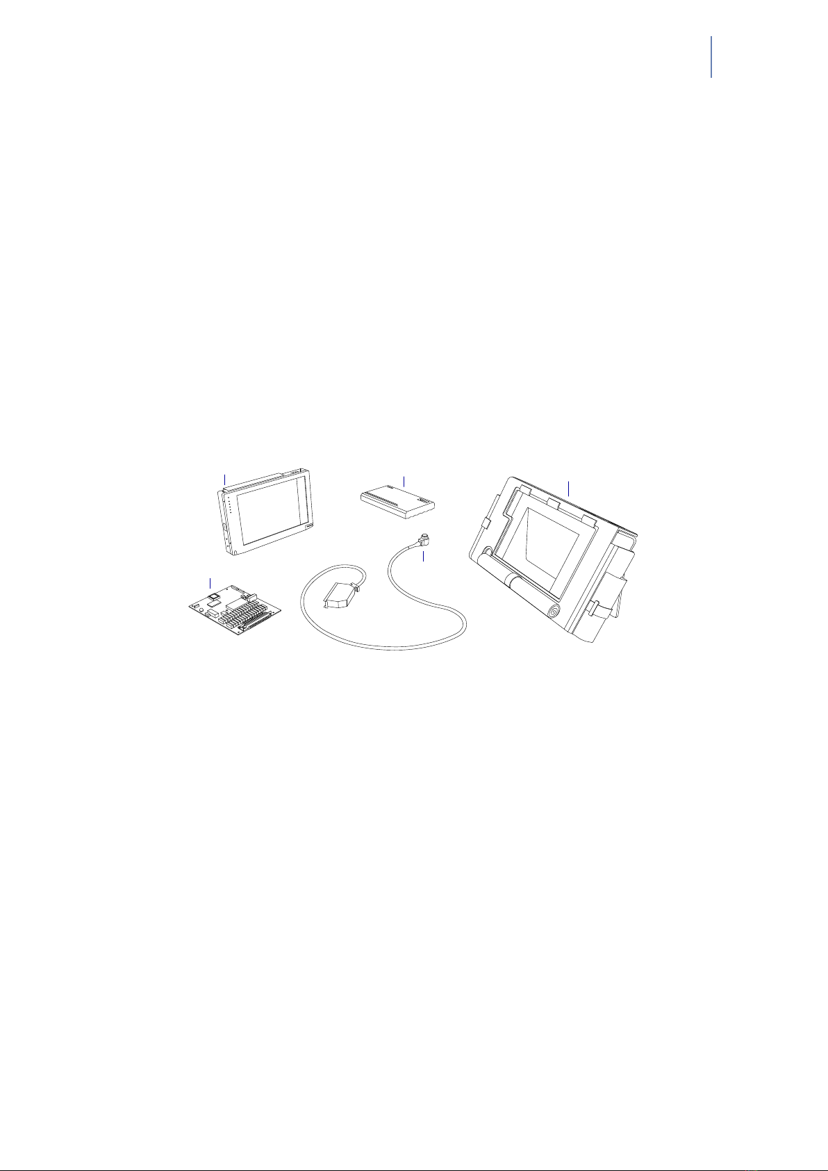
e Resistance Spot Weld Analyzer consists of several parts (Figure 2.1). e base unit
consists of a Windows-based tablet PC with an attached DSP board and installed so-
ware. e probe has a 52-element matrix transducer which connects to the DSP board.
An external battery provides up to 6 hours of run time when disconnected from a power
source. A charger/AC adapter provides power for simultaneous device operation and
battery charging. A so case holds all these components together and provides protec-
tion against shock and mechanical damage.
Tablet PC External battery Soft case
DSP board Probe
Figure 2.1 RSWA Components
9 9
9 9

4Original RSWA Hardware Manual
10 10
10 10
5
Chapter 3
Ultrasonic Probe
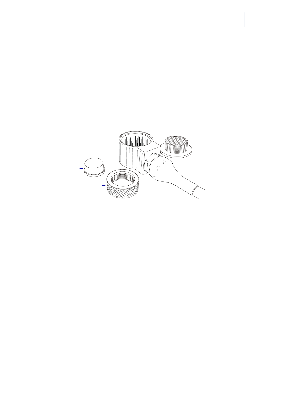
e probe consists of a multiple coax cable and an ultrasonic transducer. is is the most
critical part of an RSWA. A malfunctioning or damaged probe may not provide accurate
measurements. Figure 3.1 shows the major parts of the probe.
Housing Matrix transducer
Delay line
Coupler
Figure 3.1 Parts of RSWA transducer
3.1 Usage
e front face of the transducer is very fragile. Check that there is no dust, grease, or
any other foreign particles between the front face of the probe and the delay line be-
fore mounting the delay. e delay and the coupler are the only replaceable parts on the
probe. Please do not try to disassemble the protective case, take out the matrix trans-
ducer, or detach the cable from the protective case as this will damage the probe beyond
repair.
3.2 Cleaning and Maintenance
• Clean the front face and the thread of the transducer. If possible, use isopropyl alco-
hol, dry using an air jet
• Clean the face of the delay which will be in contact with the front face of the trans-
ducer and the collar using the same technique, dry with an air jet
• For operation, a very thin layer of a standard ultrasonic gel should be applied between
the transducer front face and the delay to provide sufficient acoustical contact
• Make sure the gel is clean and there are no air bubbles in it
• During storage or transportation, the front face of the transducer must be protected
with the delay or with a protection cap
11 11
11 11

6Original RSWA Hardware Manual
• When storing the transducer for long periods of time (longer than a month), make
sure there is no gel le on the surface of the transducer
• Under normal operating conditions, the gel layer should be replaced each month; In
a warm and dry environment the gel should be replaced more oen
Warning: Ensure the delay line is face up before attaching the coupler
12 12
12 12
7
Chapter 4
CPU Unit
e CPU unit is a fully functional computer (a Tablet PC) which runs the RSWA so-
ware.
4.1 Features
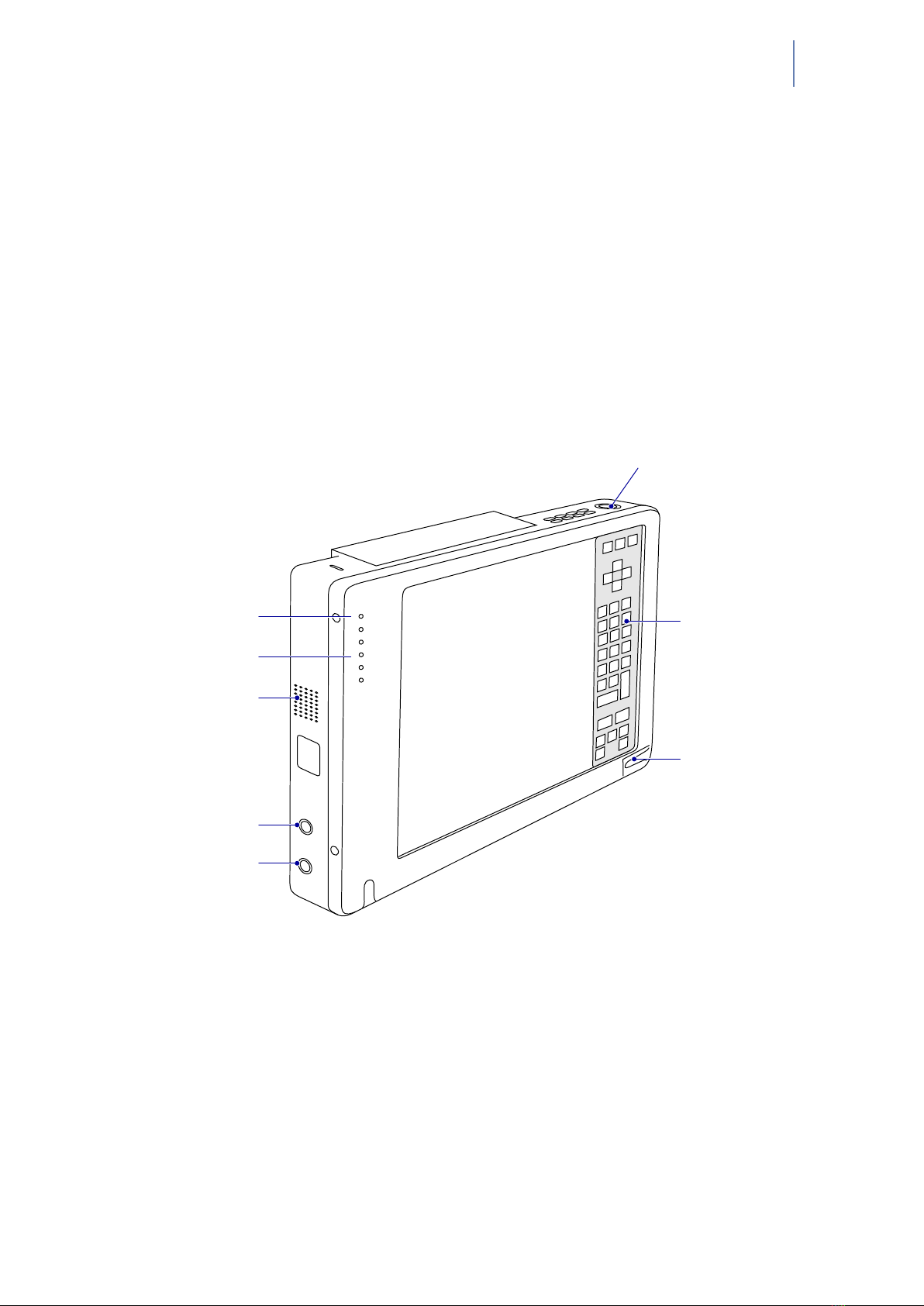
Microphone
System status LEDs
Speaker
Headphone jack
Microphone jack
Suspend/resume button
Hotpad area
Stylus
Figure 4.1 Tablet PC parts (front view)
13 13
13 13
8Original RSWA Hardware Manual
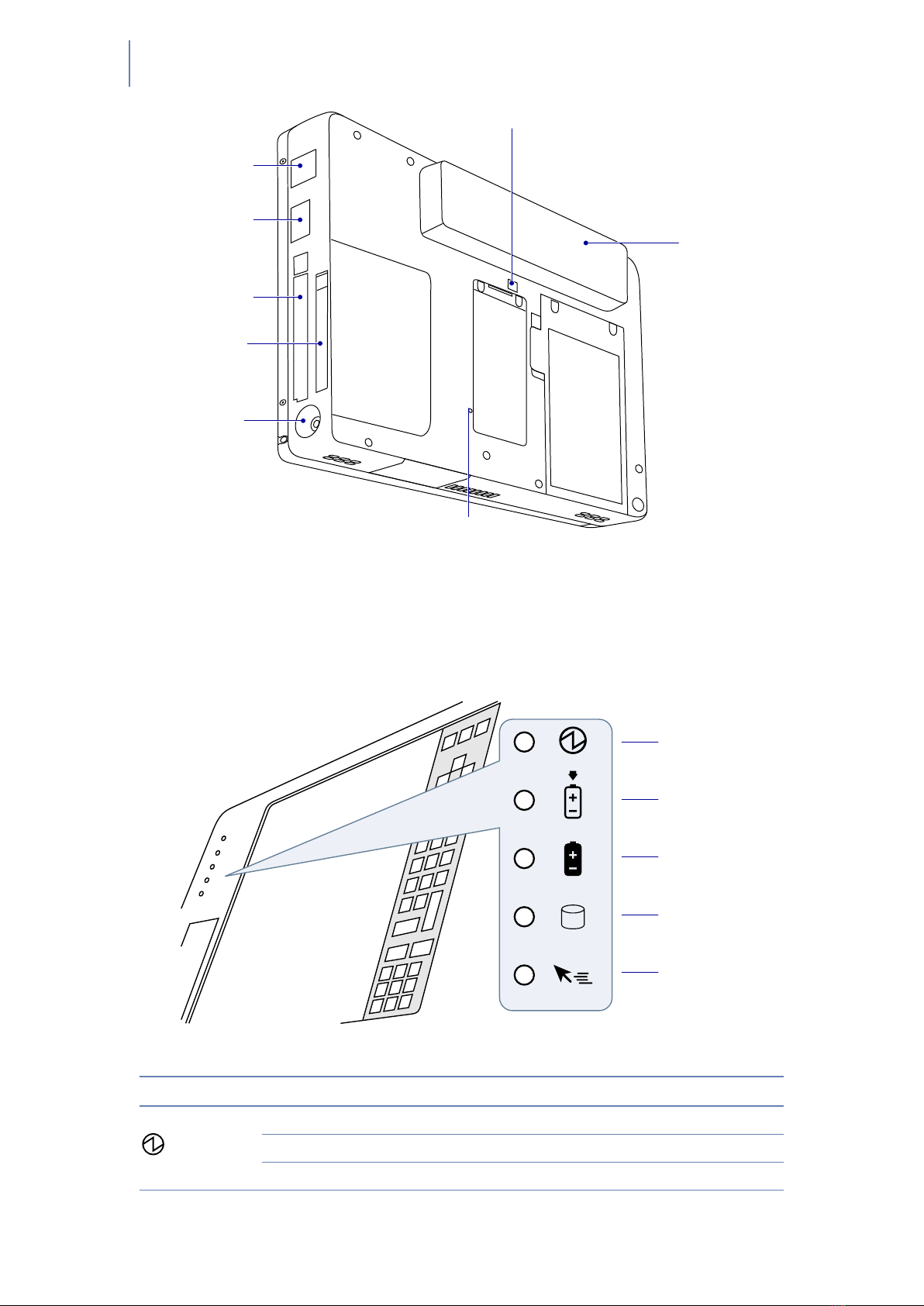
Modem port
USB port
PCMCIA slot
Compact flash slot
DC power connector
Internal Battery release switch
Internal Battery pack
Reset button
Figure 4.2 Tablet PC parts (back view)
4.2 Status Indicators
Status indicators show the status of system functions such as system power and internal
battery charge level. e location of these indicators is shown in Figure 4.3.
Power
Charge/DC in
Internal battery
HDD access
Hovering
Figure 4.3 Status indicators
Icon LED State Remarks
Power Green (continuous) On State or Idle Mode
Green (blinking) Suspend-to-RAM State
Off Off State or Save-to-Disk State
14 14
14 14
Chapter 4 CPU Unit System States 9
Icon LED State Remarks
Charge Green • AC adapter and internal battery are available
and system is not charging (internal battery
fully charged)
• AC adapter is available but internal battery is
not present
Amber (continuous) AC adapter and internal battery are available
and system is charging
Amber (blinking) AC adapter and internal battery are available
and waiting to charge (internal battery is out of
thermal range)
Off AC adapter is not available
Internal Battery Green Internal battery charge is 100% – 50%
Amber Internal battery charge is 49% – 13%
Red Internal battery charge is 12% – 0%
Red (blinking fast) ere is an internal battery error
Off Internal battery is not installed
HDD Access Green Displayed when hard disk drive is accessed
Off Hard disk drive is not being accessed
Hovering Green Hovering mode is enabled
Off Hovering mode is disabled
4.3 System States
On Mode
e system is running and the display screen is on.
Idle Mode
Some system functions are regulated or turned off to conserve power. e display
screen may be turned off. e system returns to the On state when pen activity
or other input is detected.
Suspend-to-RAM Mode
System operation is suspended. Most system functions are turned off to conserve
power. Power to memory is on, maintaining data in programs that were running
before system operation was suspended. e system does not respond to the pen
or other input when in Suspend-to-RAM mode. Push the power button return
back to On state.
Save-to-Disk Mode
System operation is suspended. All system functions are turned off to conserve
power. Active data in programs that were running before suspending system
15 15
15 15

10 Original RSWA Hardware Manual
operation is stored on the hard disk drive. e system does not respond to the
pen or other input. Push the power button return back to On state.
Off Mode
All system functions are turned off to conserve power. e system does not re-
spond to the pen or other input. e system boots at the next system power-on.
Note: e system consumes the same amount of power whether it is in Save-to-Disk
mode or Off mode.
Your system can be congured to enter some of these states automatically aer a period
of inactivity to conserve battery power.
4.4 Screen Protector
Using a screen protector will help insure that the screen remains as clear as possible.
When installed, the screen protector becomes a durable, replaceable surface that protects
the display from abrasion.
Note: e tablet PC is not waterproof. Do not pour liquids on the system or wash it
with a wet cloth.
To install a new screen protector:
1. If a screen protector is already installed on the display screen, remove it before in-
stalling the new screen protector. e screen protector is held onto the display screen
surface by a thin strip of adhesive around the edges. A notch in one corner of the
screen protector allows you to slide your ngernail under the screen protector for
easy removal.
2. Clean the display by wiping the screen surface gently using a so cotton cloth damp-
ened with denatured alcohol. Ensure that all residues have been removed from the
screen before applying a new screen protector.
3. Remove the protective coating from the adhesive side of the screen protector rst.
Apply the screen protector to the display screen surface. When doing so, orient the
screen protector with the adhesive side of the screen protector facing the display
screen and the notched corner of the screen protector toward the lower le corner
of the display screen.
4. Apply pressure to the screen protector with your nger using a continuous wiping
motion along the edges. e adhesive sets completely within 48 hours. To ensure a
good seal between the screen protector and the display, do not li the screen protec-
tor from the display once it has been applied.
5. Remove the protective plastic cover from the face of the screen protector.
6. Clean any residue remaining on the screen protector by wiping gently with a so
cotton cloth dampened with denatured alcohol. Wipe the screen protector with a
so dry cloth to remove any low-tack adhesive.
16 16
16 16
Chapter 4 CPU Unit Using the Hotpad 11
4.5 Storing
Store the equipment in the Off state with a fully charged external battery installed. e
external battery always provides power to some system components even when the sys-
tem is in the Off state. If the system is stored with the external battery removed, these
components are powered by the system’s internal battery. e internal battery is not de-
signed for extended use and will discharge in a short period of time; this could result in
damage to the internal battery. You can store the equipment in the Off state for about
30 days with a fully charged external battery installed. Aer this period, the external
battery pack should be recharged or replaced with a charged external battery.
4.6 Using the Hotpad
e hotpad area consists of several touch screen “keys” on the right side of the system
display that you can use to change several settings. e hotpad allows you to:
• Adjust the display and speaker settings
• Invoke right mouse button
• Invoke hovering capability
• Use as a numeric pad
• Use as a NumLock key
To use a hotpad key, tap directly on it with the pen. You can also press and hold the pen
tip against the Volume and Brightness hotpad keys to automatically repeat the previous
hotpad function. e location of each hotpad key is shown in the table below.
Icon Name Description
Escape Functions the same as the Esc key on a typical
keyboard
Display Each time the Display Device hotpad key is tapped, the
display unit is switched (in the following order): LCD
→ CRT → both LCD and CRT → back to LCD
NumLock Acts in the same way as the NumLock on the keyboard
(default is Off)
Cursor Control Acts in the same way as the cursor keys on a keyboard
Numeric Keypad Acts in the same way as the numeric keypad on a
keyboard (note: “BS” signies “Backspace”)
Right Mouse Button Switches the pen function from le mouse button to
right mouse button emulation for a single mouse event
aer tapping the hotpad
Pen Hovering Switches the hovering mode on or off; throughout the
hovering mode, the hovering status indicator is lit
green
17 17
17 17

12 Original RSWA Hardware Manual
Icon Name Description
Speaker Volume Decrease/Mute/Increase the speaker volume
Brightness Control Changes the luminance of the display backlight;
changes in brightness level can be monitored with the
on-screen indicator
4.7 Using Hovering Mode
Selecting the pen hovering icon on the keypad provides the user with better cursor con-
trol. When the hovering option is enabled, the cursor can be positioned over an icon
without activating it. is is useful when you are performing procedures that require
accurate cursor positioning, such as when simulating a mouse rollover, selecting a small
icon, or beginning a paint session.
• To enable hovering, tap the Pen Hovering icon on the keypad. e Hovering system
status indicator light illuminates green when hovering is selected.
• To disable hovering, tap the Pen Hovering icon again. e Hovering system indicator
light is off when hovering is not selected.
18 18
18 18

13
Chapter 5
DSP Board
e DSP (Digital Signal Processing) Board connects the transducer with the computer.
e major parts of the board are:
DSP
Handles communications with the computer, controls all the activity of various
components on the board, provides certain stages in signal processing
Pulser
Sends a short electrical pulse to the transducer.
Receiver
Receives electrical signals coming back from the transducer.
Multiplexer
Redirects signals from pulser to a particular element in the transducer.
ADC (Analog-to-digital converter)
Converts electrical signals into a digital form.
19 19
19 19

14 Original RSWA Hardware Manual
20 20
20 20
Table of contents
Other Tessonics Measuring Instrument manuals


Popular Measuring Instrument manuals by other brands


Electro Industries
Electro Industries Shark 100 Installation & operation manual

JEWELL
JEWELL 781 user manual

Vega
Vega VEGAPULS C 23 operating instructions

Tektronix
Tektronix RSA306 installation instructions

Endress+Hauser
Endress+Hauser Prosonic T FMU30 Brief operating instructions

Kreg
Kreg KMS7102 Instructional manual


