Test Equipment Depot HM8123 User manual

18 Subject to change without notice
HM8123
2.6 GHz Programmable Counter
HM8123
Frequency range from 0 Hz to 2.6 GHz
400 MHz time base with 0.5 ppm stability
Two identical inputs, up to 200MHz each
9-digit resolution at 1 sec. gate time
9 measurement functions, external gate and arming
Input for external time base (reference signal 10MHz)
HZ20 Connector
BNC to 4mm socket
HZ33, HZ34
Test cable BNC/BNC
HZ42 19“ Rackmount kit 2RU
99 Washington Street
Melrose, MA 02176
Fax 781-665-0780
TestEquipmentDepot.com

Accuracy: (resolution ± ext. gate time error x
frequency A)/total
Pulse resolution: 10 ns 10 ns
Ext. gate error: - 100 ns
Time interval / Average time interval
(Input A = start; input B = stop)
LSD: 10 ns (10 ns to 1 ps in "average” mode)
Resolution: 1 LSD (1 or 2 in "average” mode)
Accuracy: ± (resolution + trigger error + system
error)/time interval ± time basis uncertainty
(system error: ‹ 4 ns)
Number of average: N = 1-25 LSD = 10 ns
N = 26-2500 LSD = 1 ns
N = 2501-250000 LSD = 100 ps
N = 250001 – 25000000 LSD = 10 ps
N = › 25000000 LSD = 1 ps
RPM measurement
NPR1) presetting: 1 – 65535 pulses per revolution
Gate time: 330 ms fixed
LSD: 7.5 x 10⁻⁸ revolution speed
Resolution: 1 or 2 LSD
Accuracy: ± (trigger error/0.33) ± time basis error
Offset
Range: Covers the entire measurement range
Resolution: Same resolution as in normal measurement. If the
gate time is changed in the offset mode, the offset resolution is the
reference value resolution or the current reading resolution
(whichever is less precise).
Gate time
Range: 1 ms – 65 sec.
Resolution: 1ms
External gate time: min. 20 μs
Time base
Frequency: 200 MHz clock rate; 10 MHz crystal
Stability: ± 2 x 10⁻⁷ between +10° C and +40° C
Ageing: ‹ 0.27 ppm per month, 0.05 ppm per day
External Reference: 10 MHz ± 20 ppm
Miscellaneous
Safety class: Safety Class I (EN61010-1)
Display: LCD display (83 x 21 mm)
Power supply: 115/230 V ± 10 %, 45-60 Hz, 40 VA
Operating temperature: +10° C to +40° C
Max. relative humidity: 10 %-90 % (without condensation),
5%-95%RH
Dimensions (W x H x D): 285 x 75 x 365 mm
Weight: approx. 4 kg
1) NPR=number of pulses per revolution
Accessories supplied: Operator’s Manual and power cable
Optional accessories: HZ10 Silicone test leads, HZ42 19” Rackmount kit 2RU,
HZ33/34 Test cable, HZ24 Attenuator 50Ω, HZ20 Adapter plug
2.6 GHz Universal Counter HM8123
Valid at 23 °C after a 30 minute warm-up period
Input characteristics (Input A and B)
Frequency range:
0 – 200 MHz (DC-coupled)
10 Hz – 200 MHz (1 MΩ, AC-coupled)
500 kHz – 200 MHz (50 Ω, AC-coupled)
Input impedance: 1 MΩ II 30 pF or 50 Ω (switchable)
Attenuation: 1:1, 1:10, 1:100 (selectable)
Sensitivity: (normal triggering)
0 to 80 MHz 20 mVrms (sine wave), 80 mVpp (pulse)
80 MHz to 200 MHz 60 mVrms (sine wave)
20 Hz to 80 MHz 50 mVrms (sine wave, auto trigger)
Trigger (programmable via encoder or software)
Attenuation: Trigger level: Resolution:
1:1 0 to ± 2 V 1 mV
1:10 0 to ± 20 V 10 mV
1:100 0 to ± 200 V 100 mV
Max. input voltage:
Input 1 MΩ: 250V (DC + ACpeak) from 0 to 440Hz
decreasing to 8 Vrms at 1 MHz
Input 50 Ω: 5V
rms
Minimum pulse duration: ‹5 ns for single pulse
Input noise: (typ.) 100 μV
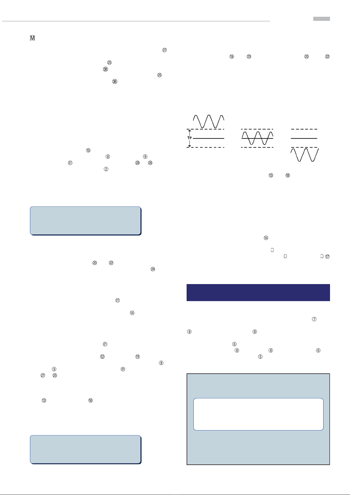
Auto trigger (AC coupling): trigger point: 50% of peak-to-peak value
Trigger slope: positive or negative
Filter: 100 kHz low-pass filter (switchable)
Input characteristics (Input C)
Frequency range: 100 MHz - 2.6 GHz
Input sensitivity: up to 1 GHz: 30 mVrms (typ. 20 mVrms)
1 GHz-2.6 GHz: 100 mVrms (typ. 80 mVrms)
Input impedance: 50 Ω nominal
Max. input voltage: 5 V (DC + ACpeak)
Input characteristics
External Reset Reference Gate/Arming
Input impedance: 5 kΩ 500 Ω 5 kΩ
Max. input voltage: ± 30 V ± 20 V ± 30 V
Input sensitivity: - typ. 2 Vpp -
High level: ›2V - ›2V
Low level: ‹ 0.5 V - ‹ 0.5 V
Min. pulse duration: 200 ns - 50 ns
Input frequency: - 10 MHz -
Min. eff. gate time: --20μs
Measurement functions
Frequency A/B/C; period duration A; width A; duty cycle A; totalize A;
RPM A; frequency ratio A:B; time interval A:B; totalize A during B;
time interval A:B (average); phase A to B; burst measurements
Frequency measurement (Inputs A, B, C)
Frequency range: 0 to 200 MHz (2.6 GHz)
LSD: (1.25 x 10⁻⁸ s x frequency) / measurement time
Resolution: ± 1 or 2 LSD
Accuracy: ± (resolution / frequency ± time inaccuracy
± trigger error / measurement time)
Period duration measurement
Range: 10000 sec. to 5 ns
LSD: (1.25 x 10⁻⁸ s x period) / measurement time
Resolution: 1 or 2 LSD
Accuracy: ± resolution / period
± (trigger error B / measurement time)
Totalization A
(manual control) (external control)
Range: 0 – 200 MHz 0 – 200 MHz
Min. pulse duration: 10 ns 10 ns
LSD: 1 count ± 1 count
Resolution: LSD LSD
Test Equipment Depot - 800.517.8431 - 99 Washington Street Melrose, MA 02176
FAX 781.665.0780 - TestEquipmentDepot.com

Important hints
(1) (2) (3) (4) (5)
Symbols
Symbol 1: Attention, please consult manual
Symbol 2: Danger! High voltage!
Symbol 3: Ground connection
Symbol 4: Important note
Symbol 5: Stop! Possible instrument damage!
Unpacking
Please check for completeness of parts while unpacking. Also
check for any mechanical damage or loose parts. In case of
transport damage inform the supplier immediately and do not
operate the instrument.
Positioning
Two positions are possible: According to picture 1 the front
feet are used to lift the instrument so its front points slightly
upward. (Appr. 10 degrees)
If the feet are not used (picture 2) the instrument can be com-
bined with many other HAMEG instruments.
In case several instruments are stacked (picture 3) the feet rest
in the recesses of the instrument below so the instruments can
not be inadvertently moved. Please do not stack more than 3
instruments. A higher stack will become unstable, also heat
dissipation may be impaired.
picture 1
picture 2
picture 3
Important hints
Transport
Please keep the carton in case the instrument may require later
shipment for repair. Losses and damages during transport as a
result of improper packaging are excluded from warranty!
Storage
Dry indoor storage is required. After exposure to extreme tem-
peratures, wait 2 hr before turning the instrument on.
Safety instructions
The instrument conforms to VDE 0411/1 safety standards appli-
cable to measuring instruments and it left the factory in proper
condition according to this standard. Hence it conforms also
to the European standard EN 61010-1 resp. to the internatio-
nal standard IEC 61010-1. Please observe all warnings in this
manual in order to preserve safety and guarantee operation
without any danger to the operator. According to safety class 1
requirements all parts of the housing and the chassis are con-
nected to the safety ground terminal of the power connector.
For safety reasons the instrument must only be operated from
3 terminal power connectors or via isolation transformers. In
case of doubt the power connector should be checked according
to DIN VDE 0100/610.
Do not disconnect the safety ground either inside
or outside of the instrument!
– Opening of the instrument is only allowed to qualified per-
sonnel
– Prior to opening, the instrument must be disconnected from
the line voltage and all other inputs/outputs.
In any of the following cases the instrument must be taken out
of service and locked away from unauthorized use:
– Visible damage
– Damage to the power cord
– Damage to the fuse holder
– Loose parts
– No operation
– After long term storage in an inappropriate environment,
e.g. open air or high humidity.
– Excessive transport stress
Proper operating conditions
Operation in the following environments: industry, business and
living quarters, small industry. The instruments are intended
for operation in dry, clean environments. They must not be ope-
rated in the presence of excessive dust, humidity, nor chemical
vapours in case of danger of explosion.
The maximum permissible ambient temperature during ope-
ration is +10 to +40 deg. C. In storage or during transport the
temperature limits are: –40 to +70 deg. C. In case of exposure to
low temperature or if condensation is suspected, the instrument
must be left to stabilize for at least 2 hrs prior to operation.
In principle the instrument may be used in any position, however
sufficient ventilation must be ensured. Operation for extended
periods of time requires the horizontal or tilted (handle) posi-
tion.
Nominal specifications are valid after 30 minutes warm-up at
23 deg. C. Specifications without tolerances are typical values
taken of average production units.
STOP
STOP
STOP

Important hints
Warranty and Repair
HAMEG instruments are subject to a strict quality control. All
instruments are burned in for 10 hrs prior to shipment. Almost
all early failures are detected by intermittent operation. After
burn-in a thorough test of all functions and of quality is run, all
specifications and operating modes are checked.
In case of claims during the two years warranty period please
contact the dealer from whom you purchased your HAMEG
instrument. Customers from the Federal Republic of Germany
may directly contact HAMEG for warranty processing in order
to speed up the procedure.
The proceeding of repairs during the warranty period is subject
to our terms of warranty which are available on our website
(http://www.hameg.com). Even after expiry of the warranty
period please do not hesitate to contact our HAMEG customer
service for repairs and spare parts.
Return Material Authorization (RMA):
Before sending back your instrument to HAMEG do apply for
a RMA number either by fax or on the Internet: http://www.
hameg.de.
If you do not have suitable packaging for the in-strument on
hand please contact the HAMAG sales department (Tel.: +49
empty original cardboard box.
Maintenance
The instrument does not require any maintenance. Dirt may
be removed by a soft moist cloth, if necessary adding a mild
detergent. (Water and 1 %.) Grease may be removed with ben-
zine (petrol ether). Displays and windows may only be cleaned
with a moist cloth.
Do not use alcohol, solvents or paste. Under no
circumstances should any fluid be allowed to get
into the instrument. If other cleaning fluids are
used damage to the lacquered or plastic surfaces is
possible.
Line fuse
The instrument has 2 internal line fuses: T 0.8A. In case of a
blown fuse the instrument has to be sent in for repair. A change
of the line fuse by the customer is not permitted.
Power switch
The instrument has a wide range power supply from 105 to 253
V, 50 or 60 Hz ± 10 %. There is hence no line voltage selector.
STOP
STOP
Test Equipment Depot - 800.517.8431 - 99 Washington Street Melrose, MA 02176
FAX 781.665.0780 - TestEquipmentDepot.com

Controls and display
Frontpanel controls
POWER (pushbutton)
Power switch, mains input connector on rear panel
GATE (LED)
The GATE LED will be on for the duration of the gate time and
synchronisation time, i.e. for the duration of one complete
measurement.
REMOTE (LED and pushbutton)
The REMOTE LED will be on if the instrument is under
control via the interface. By pushing the REMOTE button
operation will be returned to manual.
Display (LCD)
Display of measurement results and additional information
ESC (pushbutton)
Escape pushbutton (menu)
ENTER (pushbutton)
Enter pushbutton (menu)
SELECT (pushbutton)
Selects a menu or part thereof.
pushbuttons
These arrow pushbuttons are used to control the menu and
the parameters.
Rotating knob
Knob for entering parameters
GATE TIME (pushbutton)
Setting of gate time
LEVEL B (pushbutton)
Setting of channel B trigger level
LEVEL A (pushbutton)
Setting of channel A trigger level
1 : 10 pushbutton
Input attenuator, total attenuation 100 times.
Controls and display
DC (pushbutton)
Selects the coupling of the corresponding channel.
Button DC lit = DC coupling
Button DC dark = AC coupling
Slope (pushbutton)
This pushbutton selects the trigger slope. A lighted pushbut-
ton indicates triggering on the negative slope, an unlighted
pushbutton indicates triggering on the positive slope.
50 (pushbutton)
This pushbutton connects an internal 50 resistor to the
input in order to allow operation in 50 systems.
LP 50 kHz (pushbutton)
This pusbuttons inserts a low pass filter in order to sup-
press hf signals from interfering with triggering from low
frequency signals.
TRIG (LED)
Indicate triggered operation
INPUT A, INPUT B (BNC connectors)
Input connectors for measuring signals DC to 200 MHz
AUTO TRIG (pushbutton)
Selects automatic triggering operation indicated by the
pushbutton lighting up.
INPUT C (SMA connector)
Input for measuring signals 100 MHz to 2.6 GHz
RESET / V (pushbutton)
Button with two functions:
1
st Pressing this button will stop any measurement, erase
the display and start a new measurement.
2
nd Setting the trigger level with the numerical keys , the
entered value will be accepted with the unit Volts (V).
TRIG / GHz/s (pushbutton)
Button with two functions:
1
st Pressing this button will start a measurement in ARMED
mode.
2
nd Setting the gate time with the numerical keys , the
entered value will be accepted with the unit seconds (s).
HOLD / mV (pushbutton)
Button with two functions:
1
st Pressing this button will freeze the display.

Controls and display
2
nd Setting the trigger level with the numerical keys ,
the entered value will be accepted with the unit millivolts
(mV).
ARMED / MHz (pushbutton)
Button with two functions:
1
st Pressing this button will select the ARMED mode.
2
nd Setting the gate time with the numerical keys , the
entered value will be accepted with the unit milliseconds
(ms).
OFFSET / Hz/ns (pushbutton)
Pressing this button will activate the OFFSET function.
GATED / kHz/us (pushbutton)
Pressing this button will activate the GATED mode.
Function pushbuttons to
These buttons have two functions:
1
st The measurements function are called by operating these
buttons. The corresponding button will light up.
2
nd Setting the trigger level or the gate time, the desired
value can be entered with this buttons and the unit buttons
(mV , V and ms , s ). Also refer to chap. Gate time
and Triggering. None of these button is lit.
FREQ A Frequency channel A
FREQ B Frequency channel B
FREQ C Frequency measurement channel C
PER A Period channel A
Width A Pulse width channel A
A : B Frequency ratio of channels A : B
Duty A Duty cycle channel A
TI AB Time interval AB
TI avg AB Time interval AB averaged
Phase AB Phase difference AB
RPM A Rpm measurement channel A
TOTAL A Event counting channel A
TRIG/ARM INPUT (BNC connector)
External gate control input
Rear Panel
Interface
RS-232 interface (Options: IEEE-488, USB)
A (BNC connector)
Trigger signal channel A output (e.g. for display on a scope).
Signal level 0 to + 5 V (TTL level)
B (BNC connector)
Trigger signal channel B output (e.g. for display on a scope).
Signal level 0 to + 5 V (TTL level)
GATE (BNC connector)
Gate view output. This output will be high as long as the gate
is open during a measurement.
10 MHz Ref. (BNC connector)
External reference input (10 MHz)
RESET (BNC connector)
External reset signal input (TTL level). The function is iden-
tical to that of the RESET pushbutton .
Mains input connector
Test Equipment Depot - 800.517.8431 - 99 Washington Street Melrose, MA 02176
FAX 781.665.0780 - TestEquipmentDepot.com

Introduction to the HM8123 operation
First time operation
Please observe the following hints especially during first time
operation:
– This instrument has a wide-range power supply designed
for 115 to 230 V, 50/60 Hz ±10 %, i.e. it will operate from 105
to 254 V.
– This instrument may only be connected to a wall outlet with
a three-conductor safety ground terminal or to an isolation
transformer of safety class 2.
– There are two fuses inside of the instrument which are not
serviceable by the customer.
– There are no visible damages to the instrument.
– There are no loose parts floating around inside.
Switch-on
After pressing the red POWER pushbutton the display will
show „2.6 GHz counter Hameg HM8123“ and the current softwa-
re version installed, e.g. 1.03. During initialization the HM8123
will automatically load the configuration stored in memory 0.
Operation of the HM8123
Display
The display will show the actual measurement function, the
result and the reference source (internal or external).
FREQUENCY A:
10.000000 MHz
Ref: INT
Pressing the HOLD button will activate the Hold function, the
pushbutton will light up. The present result will be frozen.
The Hold function will be deactivated by pressing the button
again or by selecting another function. The pushbutton light
will be off.
FREQUENCY A:
10.000000 MHz
Ref: INT
HOLD
By pressing the pushbutton OFFSET the Offset function will
be activated, the pushbutton OFFSET will light up. In this
mode the present result will be taken as the reference value
and indicated in the display (e.g. REF: 100.000000MHz). For all
subsequent measurements this value will subtracted from the
result, the difference will be displayed.
The following picture shows the display for a reference frequen-
cy of 100 MHz and a measured frequency of 99.99 MHz.
FREQUENCY A:
–10.000 kHz
Ref: INTREF: 100.000000 MHz
Measurement functions
All measurement function are called by the function keys to
. The selected function key will light up. The function selected
will also be shown in the first line of the display.
FREQ A, FREQ B, FREQ C
Frequency measurement of the signal connected to the channel
selected. The frequency range of channels A and B is DC
to 200 MHz and of channel it is 100 MHz to 2.6 GHz.
A high input sensitivity is not always desirable for frequency
measurements , as the counter will become increasingly sen-
sitive to noise on the signal. Hence frequency measurements
should be made using as much attenuation as possible and
. Any dc content of a signal should be blocked by turning the
DC pushbutton light off. DC coupling, however, is necessary
at frequencies below appr. 10 Hz (Pushbutton DC lighted). In
case a low frequency signal is superimposed by high frequency
noise select the low pass filter LP 50 kHz .
PER A
Period measurement of the channel A signal.
WIDTH A
Measurement of the pulse width of the channel A signal.
Accuracy: 0.4% at squarewave (1MHz)
A : B
Measurement of the frequency ratio of signals connected to
channels A and B . A ratio measurement is useful, for
instance, for calibration of oscillators with odd frequency. The
higher frequency should be applied to input A to achieve the
highest resolution possible.
DUTY A
Measurement of the duty cycle of the channel A signal.
Accuracy: 0.4% at squarewave (1MHz)
TI AB
In this mode Time Interval the time difference between a signal
on channel A (start pulse) and a signal on channel B (stop
pulse) will be measured.
TI avg AB
Measurement of the average of the time interval AB.
Phase AB.
Measurement of the phase difference between signals A and
B.
RPM A
Measurement of the rpm (revolutions per minute) of a signal on
channel A (e.g.rpm measurement using an optical sensor.)
The number of pulses per revolution has to be selected in the
menu (1 to 256 available).

Menu
TOTAL A
Event (pulses, periods) measurement of the channel A signal.
If the input signal disappears or if the pushbutton HOLD is
depressed the measurement will be stopped and the result
frozen. By pressing the RESET pushbutton or by a high
level on the RESET connector the display will be reset. A
new measurement will be started after the pusbutton was
released or after the RESET signal switched to low.
Gate time
The counter HM8123 totalizes the input cycles until the gate
time set has eclapsed and the trigger conditions selected are
fulfilled. Thus the effective measuring time can be longer than
the gate time set. The measuring time cannot be smaller than
one period of the signal.
The gate time can be varied between 1 ms and 65.5 s. Operate
pushbutton GATE TIME and enter the desired gate time by
using the 4 arrow keys and the knob or with the
numerical keys and the unit buttons (ms , s ). During
a measurement the GATE LED is lit. If a short gate time is
selected, the HM8123 inserts a wait time between the mea-
surements to simplify the reading of the display. In this case a
complete measuring cycle will take at least 180 ms. The wait
time can be deactivated by sending WT0 via the interface. To
activate the wait time WT1 has to be sent.
Gate Time : 500 ms
10.0000000 MHz
Ref: INT
Triggering
When using the channels A or B manual or automatic trig-
gering may be selected. The triggering of channel C signals
is not selectable, signals between 50mV and a maximum of 5V
will be automatically triggered.
Automatic triggering
Pressing the AUTO TRIG pushbutton will activate automatic
triggering, the pushbutton will light up. Please note that AC
coupling is mandatory, the pushbutton DC have to be dark.
In this mode the amplitude of the signal is measured, and the
trigger level is set to 50 % of it.
Manual Triggering
If the AUTO TRIG pushbutton is dark, manual triggering
is active. The trigger level has now to be selected manually.
Operate pushbutton LEVEL A or LEVEL B and enter the
desired trigger level by using the 4 arrow keys and
the knob or with the numerical keys and the unit buttons
(mV , V ).
The trigger level may be selected in 3 ranges:
Pushbutton Pushbutton
1:10 1:10 Triggerlevel
off off –2,000 V …. + 2,000 V
on off –20,00 V .... + 20,00 V
off on –20,00 V .... + 20,00 V
on on –200,0 V .... + 200,0 V
Level A : +0.500 V
10.0000000 MHz
Ref: INT
Optimum triggering is obtained by setting the trigger level to
about 50 % of the peak-to-peak amplitude of the input signal.
In manual mode proper triggering can be checked by the
trigger indicators and control of channels A and B
as follows:
LED on continuously: Input signal above the trigger
level selected.
LED off continuously: Input signal below the trigger
level selected.
LED blinking: Correct setting.
LED off
0V
LED on LED blinking
Suitable setting of the attenuators and is a prerequisite
for correct measurements. With too much attenuation the
residual noise of the input signal comparator will affect the
result. With too little attenuation or if the input signal is too
large the input stage may be overdriven which lead to erroneous
measurements.
With all frequency measurements AC coupling should be used
(below appr. 10 Hz DC coupling will be necessary) together with
as much attenuation as possible. Period measurements should
use DC coupling (pushbutton DC lighted) if at all possible.
If the input signal comes from a 50 system the input impe-
dance of the HM8123 have to be set to 50 (pusbutton 50
lighted).
Menu
The menu is called by pressing the pushbutton SELECT . Sub-
menus are called from the main menu by using the rotating knob
or the 2 arrow keys . The submenu selected will be
identified by an arrow >. The submenu selected will be opened
by pressing ENTER . Parameters are changed by using the 4
arrow keys or the knob . Pressing ENTER will
enter the value. Pressing ESC will return the control to the
main menu. The main menu will be left py pressing SELECT.
STORE / RECALL
REFERENCE
CONTRAST
RPM SETTINGS
DISPLAY
CALIBRATE
BEEPER
ABOUT
MENU:
>

Menu
Store/Recall
This function allows storing or recalling of an instrument con-
figuration. The HM8123 is able to store 10 configurations (0 to
9). Use the keyboard 0 – 9 to select. After turn-on the confi-
guration stored in memory 0 will be recalled automatically.
Reference
In this submenu the internal or an external reference may be
selected. If an external reference was chosen the HM8123 will
check the signal at the BNC connector 10MHz .If this fre-
quency is not accurate enough or if there is no signal, in both
cases the error message „External Reference Test failed“ will
be displayed. In this case the instrument will continue to use
its own reference. The error message will also be shown and
return to the internal standard performed if an external refe-
rence frequency deviates more than 2 Hz.
TOGGLE FREQUENCY REFERENCE
REFERENCE : INTERNAL
TOGGLE FREQUENCY REFERENCE
REFERENCE : EXTERNAL
Contrast
In this submenu the contrast of the LCD display may be set using
the arrow keys or the knob . If the contrast adjusted
is confirmed by pressing pushbutton ENTER this setting will
be stored in a non-volatile memory. If the menu is left without
confirmation the setting of the contrast with ENTER , this
setting will be lost afetr power-off. After turn-on the HM8123
will recall the value stored in the non-volatile memory.
Adjust LCD Contrast
-------------*--------------
RPM settings
This menu item allows to select the number of pulses per
revolution. This parameter is required for rpm measurements
and may be selected from 1 to 65,535 using the knob or the
4 arrow keys .
RPM : Pulses Per Revolution
500
Display
In this submenu the display may be turned off or on.
TOGGLE DISPLAY ON/OFF
Display is : ON
TOGGLE DISPLAY ON/OFF
Display is : OFF
Calibrate
It is possible to recalibrate the reference frequency (Frequency)
and the trigger levels of channels A (LEVEL A) and B (LEVEL
B). For this porpuse the calibration procedure can be ordered
at Hameg Instruments GmbH (Phone: +49 6182 - 800 500 or
STOP
We recommend that recalibrations should only
be performed by Hameg Instruments GmbH or an
authorized calibration lab. After receiving the cali-
bration procedure the warranty with respect to the
specifications will be voided.
Beeper
In this submenu the beeper can be activated/deactivated. If the
instrument configuration is stored using the Store function (see
chapter Store/Recall), the setting of the beeper is also stored.
About
After selection of this submenu the type of instrument and the
software version will be displayed.
HAMEG Instruments Universal Counter
HAMEG HM8123 1.04
Additional inputs and outputs
External Arming
External arming prevents triggering of a measurement by
undesired signals. The ARMED mode is selected by pressing
ARMED , the pushbutton will light up. A measurement can
be started either manually by pressing TRIG or by a signal
at the TRIG/ARM input .
The TRIG/ARM input connector is located on the front panel.
As long as there is a low level input signal the counter will not
start a new measurement. A measurement will be started if
the following conditions are all met: the signal at the input
switches from low to high, the trigger conditions selected are
fulfilled. The delay time caused by the arming signal is 50ns.
The measurement will be performed according to the HM8123
settings. During a measurement any signals at the TRIG/ARM
input will be ignored. A new measurement will be started after
the measurement time set has elapsed with the next positive
slope at the TRIG/ARM input .
Arming
Signal
Input A
Number of
periods counted Measurement time
Test Equipment Depot - 800.517.8431 - 99 Washington Street Melrose, MA 02176
FAX 781.665.0780 - TestEquipmentDepot.com

Remote control
External Gate
A measurement may be started and stopped by a signal at
the gate input TRIG/ARM . This input is located on the front
panel. The gated mode is entered by pressing GATED , the
pushbutton will light up. As long as there is a low level at this
input no measurement will be started. A measurement is started
by a low to high transition at the TRIG/ARM input and if the
trigger conditions are met. The measurement will be stopped
by a high to low transition at the input. This signal is of higher
priority than the gate time selected. The signal at the TRIG/ARM
input have to be within the range of 50ns to 10 s. The effective
gate time can not be shorter than 20 μs.
Ext.-Gate
Signal
Trig.-Level
Input A
Actual
gate time
Number
of counts
External Reset
The RESET BNC connector is located on the rear panel. A
high level at this input is identical to pressing the RESET push-
button : the current measurement will be halted, the result
reset. A new measurement is started when the signal switches
from high to low.
External Reference
The external reference 10 MHz BNC connector is located on
the rear panel. An external 10MHz reference may be conected to
this input. The external refrence has to be selected in the menu
(refer to paragraph Menu). This reference signal must have an
accuracy of at least ±20 ppm and an amplitude of 2 Vpp.
Gate View
The BNC connector GATE is located on the rear panel. The
gate open signal is available here e.g. for scope display. Due to
the start sync time this signal will be longer than the measu-
rement time selected.
Remote control
The HM 8123 comes with a RS-232 interface, IEEE-488 or
USB are available options. We recommend the installation ex
factory.
Interface parameters:
9600 baud, no paritybit, 8 data bits, 1 stop bit
Setup of the commands
A message to the HM8123 may consist of several commands.
The commands have to be separated by semicolon (;). After
receiving a CR (0x13) the HM8123 will start to work on the
commands received. The commands my contain upper and
lower case characters. The commands will be executed in the
order they were received. Any commands which can not be
executed in the mode selected presently will be ignored (e.g.
the command „Set measurement time“ (SMTxxxxx) would be
ignored if the event counting mode was selected.)
Listing of commands
Functions: With these commands the measurement functions
are selected.
FRA Frequency channel A (FREQ A)
FRB Frequency channel B (FREQ B)
FRC Frequency channel C (FREQ C)
PRA Period channel A (PER A)
WDA Pulse width channel A (Width A)
RAB Frequency ratio A/B (A:B)
DTA Duty cycle channel A
TI1 Time interval A to B (TI A to B)
TIA Time interval A to B averaged (TIavg A to B)
PHA Phase A to B (Phase A to B)
RPM rpm measurement channel A (RPM A)
TOT Event counting channel A (TOTAL A)
Control of measurements: With these commands parameters
may be changed.
a) Attenuators
Activates/deactivates the attenuators, corresponds to pushbut-
tons 1 : 10 and
AA0 Attenuator channel A off
AA1 Attenuator channel A 1 : 10
AA2 Attenuator channel A 1 : 100
AB0 Attenuator channel B off
AB1 Attenuator channel B 1 : 10
AB2 Attenuator channel B 1 : 100
b) Slope
Selection of trigger slope, corresponds to pushbutton SLOPE
SA0 Positive slope channel A
SA1 Negative Slope channel A
SB0 Positive slope channel B
SB1 Negative slope channel B
c) Low pass filter 50 kHz
Activates/deactivates the low pass filer, corresponds to push-
button LP 50 kHz

FA0 Low pass filter 50 kHz channel A off
FA1 Low pass filter 50 kHz channel A on
FB0 Low pass filter 50 kHz channel B off
Fb1 Low pass filter 50 kHz channel B on
d) Coupling
Selection of coupling, corresponds to pushbutton DC
ACA AC coupling channel A
DCA DC coupling channel A
ACB AC coupling channel B
DCB DC coupling channel B
e) 50
Selection of input impedance, corresponds to pushbutton 50
OAH Input impedance channel A 1 M
OAL Input impedance channel A 50
OBH Input impedance channel B 1 M
OBL Input impedance channel B 50
f) Trigger level
Selection of trigger level, corresponds to pushbuttons LEVEL
A and LEVEL B .
LVAxxxx Setting of channel A trigger level (xxxx:
±0.001 to ±200.0 V)
LVBxxxx Setting of channel B trigger level (xxxx:
±0.001 to ±200.0 V)
g) Gate time
Setting of gate time, corresponds to pushbutton GATE TIME .
SMTxxxx Setting of gate time in ms (xxxx: 1 .... 65,535 ms)
h) Wait time
Activating/Deactivating of the wait time between measure-
ments
WT0 Wait time off
WT1 Wait time on
i) ARMED
Activating/Deactivating of ARMED function, corresponds to
pushbutton ARMED
AR0 ARMED function off
AR1 ARMED function on
j) GATED
Activating/deactivating of GATED function, corresponds to
pushbutton GATED
GT0 GATED function off
GT1 GATED function on
k) OFFSET
Activating/deactivating of OFFSET function, corresponds to
pushbutton OFFSET
OF0 OFFSET function off
OF1 OFFSET function on
l) HOLD
Activating/deactivating of HOLD function, corresponds to push-
button HOLD
DH0 Display hold off
DH1 Display hold on
m) Display
Activating/deactivating the display, corresponds to menu item
Display.
DS0 Display off
DS1 Display on
n) Miscellaneous parameters
NPCxxxx Setting of pulses per revolution for rpm
measurement (xxxx: 1 ..65,535)
TRG Trigger
RES Reset
STR Starting event counting
STP Stop of event counting
Requests of parameters: These commands allow to request
parameters and the actual results from the instrument.
VER Request for software version number of the
HM8123 (e.g. 1.00)
IDN Identification string (HAMEG HM8123)
FN? Measurement function (e.g. FRA)
SMT? Gate time in ms (e.g. 400ms)
LVA? Trigger level in V of channel A (e.g. +0.100)
LVB? Trigger level in V of channel B (e.g. -1.000)
XMT Request of results, format: value, unit
MA? Settings of channel A Example:
MB? Settings of channel B } Z:50 CPL:AC FL:ON ATT:1 SLP+
Explanation:
Z:50 = Input impedance 50
CPL:AC = AC coupling
FL:ON = Low pass filter on
ATT:1 = Attenuator off
SLP+ = Positive slope
Remote control
Test Equipment Depot - 800.517.8431 - 99 Washington Street Melrose, MA 02176
FAX 781.665.0780 - TestEquipmentDepot.com
Table of contents