TeST TT AUT-MARSHALL-CBR User manual
INSTRUCTIONS
MANUAL
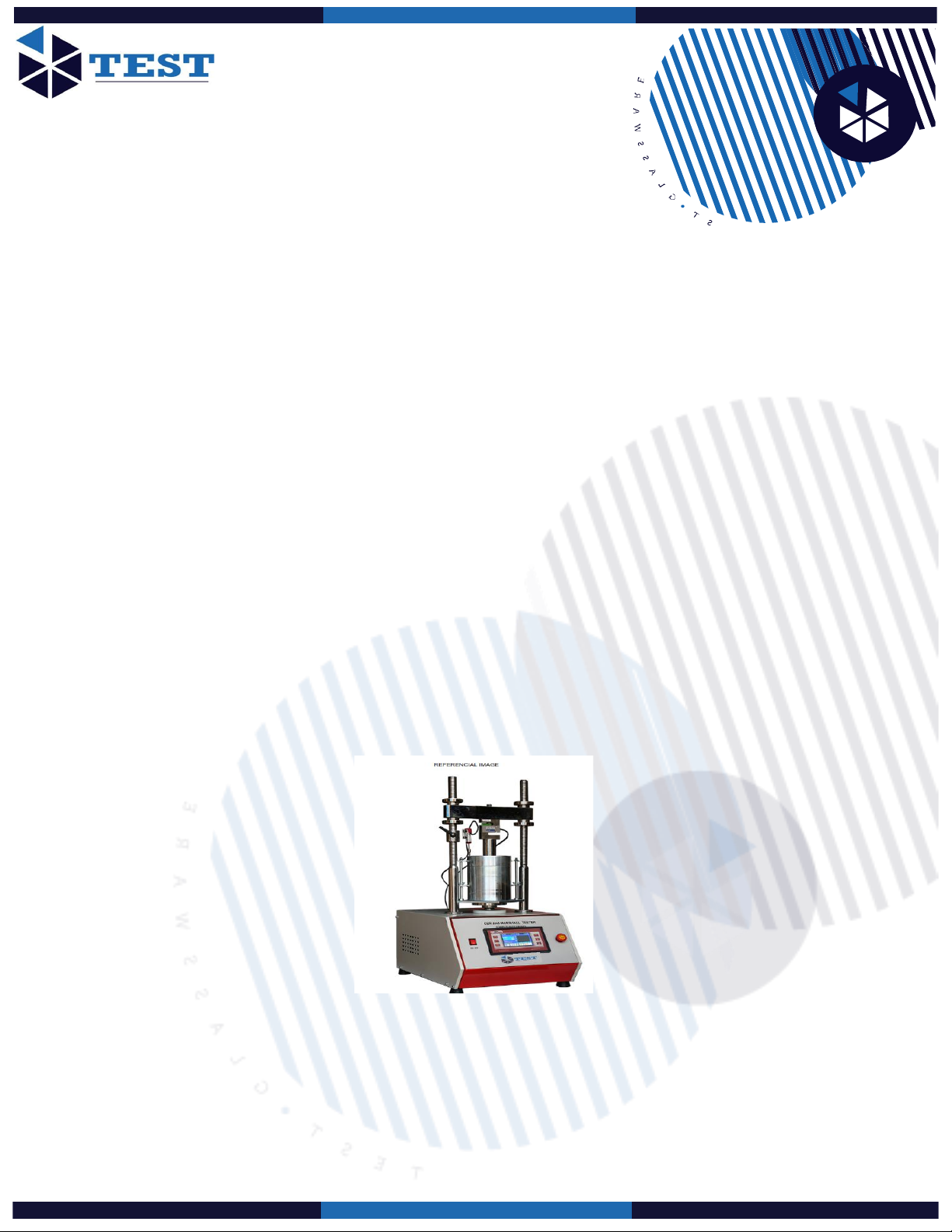
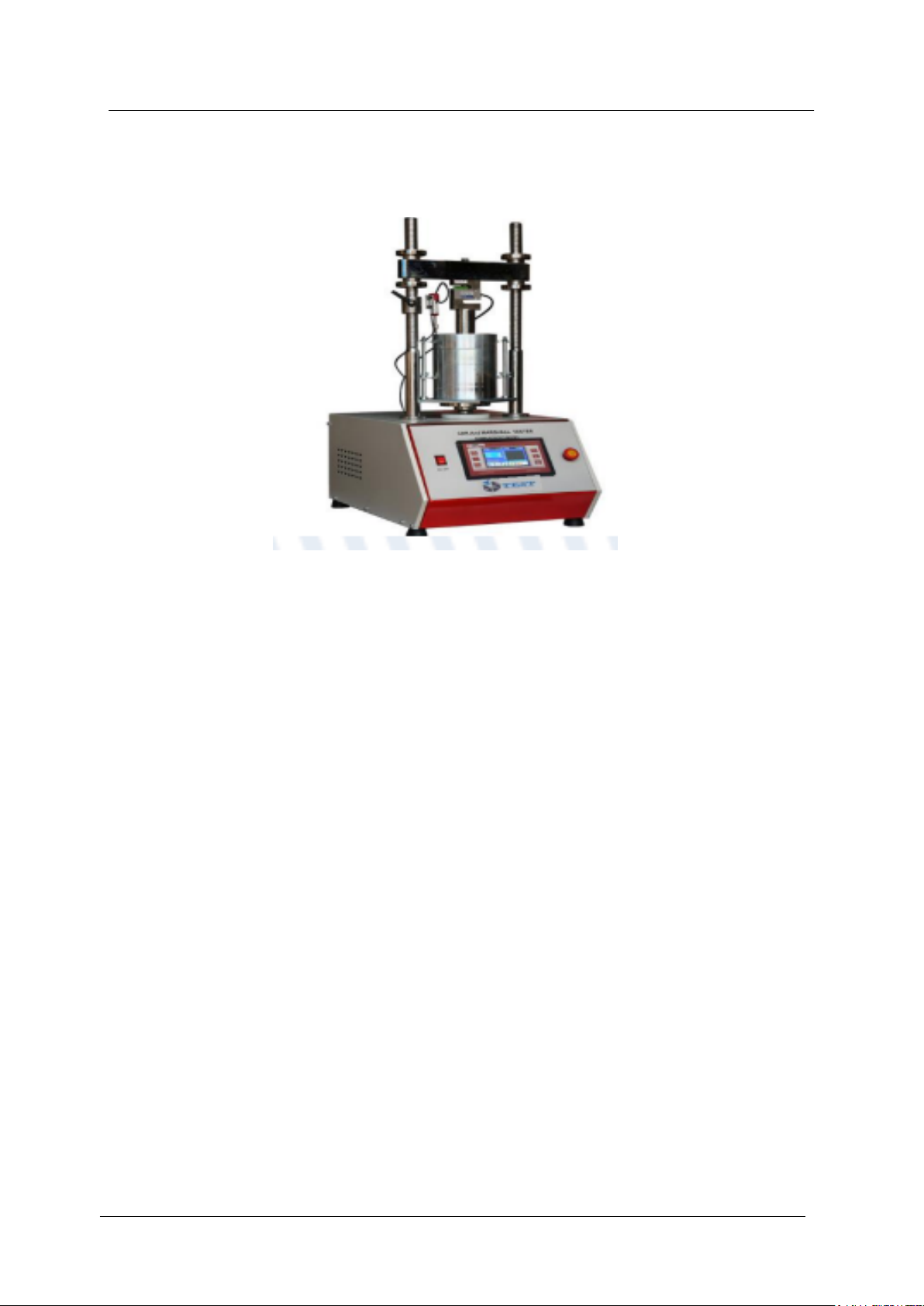
AUTOMATIC MACHINE FOR CBR AND
MARSHALL WITH LOAD FRAME
(MARSHALL: ASPHALT ANALYSIS
METHOD)
Model: TT AUT-MARSHALL-CBR
File No.: TEST- V2.3-EN
Publication Date: Sept 30 2021
Print Date: Oct 5, 2021

Contents
Section Page
WARNING 3
1 Introduction 5
2 Specification 6
3 Installation 6
4 Controls 7
5 Setting up for CBR tests 10
6 Setting up for Marshall tests 12
7 Setting up for Quick Undrained Triaxial tests 14
8 Maintenance 15
9 Connecting a DSU Readout device 16
CE Declaration of Conformity
WEEE Directive
Original Instructions 2

WARNING:
This equipment can endanger life by exposure to high voltages.
The equipment must be permanently earthed due to the high earth leakage current in the
motor and drive. Use the earth lead on the rear of the unit to connect to a permanent safety
earth. The AC inlet should not be relied on to provide a safe earth.
Service personnel must ensure all incoming supplies are isolated before working on the
equipment.
There may still be dangerous voltages present at power terminals (motor output, supply input
phases, DC bus and the brake, where fitted) when the motor is at standstill or is stopped.
For measurements use only a meter to IEC 61010 (CAT III or higher). Always begin using
the highest range. CAT I and CAT II meters must not be used on this product.
Allow at least 5 minutes for the drive's capacitors to discharge to safe voltage levels (<50V).
Use the specified meter capable of measuring up to 1000V DC and AC RMS to confirm that
less than 50V is present between all power terminals and earth.
Original Instructions 3

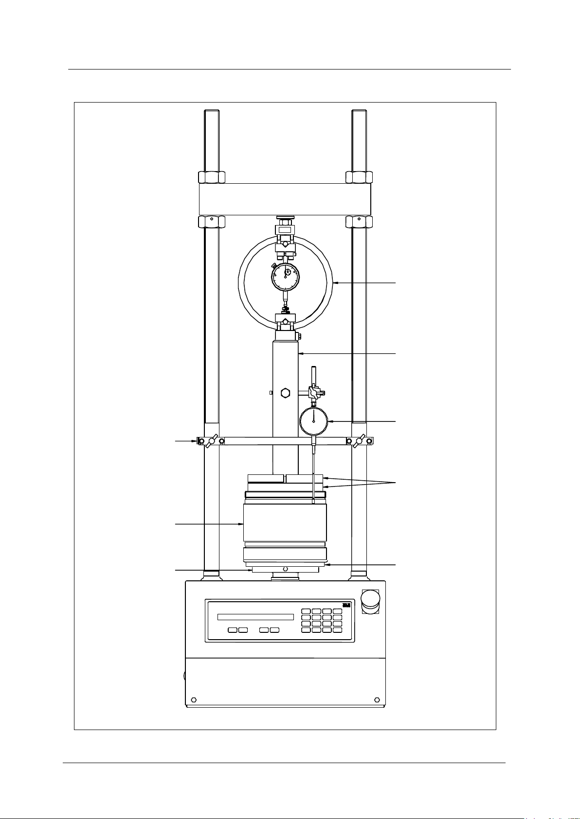
CrossheadColumn
Fitting for load ring
Locking nuts
Adjustment nuts
Alignment studs
Display
Platen
Holes for
tommy bar
Emergency
stop switch
Touch panel
keypad
Manually applied
platen movement
Figure 1.
Original Instructions 4
1 Introduction
These instructions are for machines with a serial number beginning 1895, i.e. of the
format 1895-X-XXXX.
This machine has been designed to perform compressive strength tests on soil and
asphalt samples. The following test types are built into the machine: California
Bearing Ratio (CBR), Marshall and Quick Undrained Triaxial (UU) tests. User-defined
test speeds are also allowed.
The apparatus consists of a load frame with an adjustable top crosshead mounted on
columns attached to a sturdy base casting. Loading forces of up to 50kN are applied
to the sample by means of a motor-driven platen and the speed is accurately
maintained by the control electronics and speed feedback system. The motor, gear
unit and microprocessor-controlled electronics are housed in the machine base.
Limit switches are fitted to prevent over travel on the up and down stroke of the
platen.
The user controls the machine via the front panel display screen and keypad. A
simple menu system provides speed control and all set-up operations
As well as the limit switches, the operator is protected by a stall detection system,
large emergency stop button and electrical fuses. All electrical design complies with
the relevant CE safety and interference directives.
Please note that the motor in this machine is capable of generating loads
greater than 50kN, so the operator must always be aware of the current loading
being applied in order to prevent overload. (Note that connecting the DSU readout
device provides automatic overload protection –see below)
A ball seated screw fitting located on the crosshead accepts load rings and load
transducers up to and including 50 kN.
Original Instructions 5

Two sockets at the rear of the machine provide connections for the Electronic Control
and read-out Unit (DSU). These are for use with electronic load and displacement
transducers (see section 9).
2 Specification
Dimensions
(l x w x h)
550 mm x 400 mm x 1230 mm
Weight
71 kg
Max. vertical clearance
(platen down crosshead up)
795 mm
Min. vertical clearance
(platen up crosshead down)
210 mm
Horizontal clearance
265 mm
Platen diameter
133.3 mm
Platen adaptor diameter
158.5
Platen travel
100 mm (nominal)
Platen speed
Variable 0.5 to 50.8 mm/min (0.020 –2 in/min)
2.1 Items supplied with the machine
Tommy bar for removing the platen
Platen adapter - fits on the platen to locate moulds when conducting CBR tests.
Stabilising bar - used to ensure stability and location of the penetration piston during CBR
tests and the stability piston during Marshall tests.
Stability piston - used in conjunction with the stabilising bar to provide very stable loading
conditions during Marshall tests.
Extended ball nipple - for mounting the axial strain transducer when using a 100mm
triaxial cell and load ring.
Power lead with moulded socket for connecting to the mains supply.
Communications cable (RS232) for connecting the machine to a DSU readout device.
3 Installation
3.1 The machine must be installed on a bench that is both level and designed to support
the gross weight of the machine, samples and ancillary equipment.
3.2 This equipment must be earthed via its mains input cable. A separate earth terminal
screw is provided on the rear of the unit as an optional extra safety earth and for PAT
testing connection point.
3.3 The machine contains a dc motor drive unit and the manufacturer of this drive unit
gives the following service and safety advice:
Never perform high voltage resistance checks on the wiring without first
disconnecting the drive from the circuit being tested.
When replacing a drive in an application and before returning to use, it is essential
that all user defined parameters for the product’s operation are correctly installed.
This equipment contains electrostatic discharge (ESD) sensitive parts. Observe
static control precautions when handling, installing and servicing this product.
Original Instructions 6

3.4 Power Supply
Electrical safety
Warning: Do not operate the unit without a permanent earth connection. Use the
cable provided at the rear of the unit.
Warning: Before removing any covers or performing maintenance repair and service,
isolate from electrical supply by removing mains plug. Where mains supply is
required during these activities, only competent persons should perform the work.
Check that the power supply is compatible with the requirements stated on the label
and connect in accordance with IEE regulations or to local electrical installation
regulations.
The power cable is coded as follows: -
Brown wire L Live or Power
Blue wire N Neutral
Green/Yellow wire E Earth or Ground
Note: Do not use the machine with wet hands. Dry hands before operating.
Organisations have an obligation to ensure equipment is maintained and is safe for
use. Regular Portable Appliance Testing (PAT) is one means of ensuring equipment
continues to be electrically safe. For operator safety, regular earth bonding
checks are recommended.
Do not flash test this electronic equipment.
4 Controls (refer to figures 1 & 2)
4.1 Mains ON/OFF switch (at the rear of the machine).
This will switch on the power to the machine. The display will briefly indicate
“Multiplex 50” before indicating the selected platen speed.
The LCD display has a back light which is illuminated when the machine is switched
on.
4.2 Emergency stop switch
This is the large red knob on the front panel. Pressing this switch stops the platen
from travelling in either direction. When this switch is pressed, the display will read
“EMERGENCY STOP BUTTON PRESSED Release button to proceed”. As a safety
feature, once this switch has been depressed, it latches in the off position and must
be physically pulled out to the on position before any other functions will operate.
This is a non isolated product. The signal plus control connections are not isolated
from the AC supply. [Note that the unit is isolated design of the machine].
Portable Appliance Tests (PAT)
All designed products are tested for electrical safety prior to sale.
An electrical safety test label is fitted, (usually adjacent to the mains input socket).
Should no label be found, please contact Service Department quoting the serial
number of the equipment.
If in doubt as to the most suitable connection point (which will usually be an
earth stud or an external earth connection) contact Service Department for
assistance.
Original Instructions 7

4.3 Set-up Menu
Press the SETUP key to enter set the basic machine parameters. Press the left and
right arrow keys (< and >) to scroll through the options for any particular setting. Press
the up and down arrow keys to select a different function to set. The diagram below
illustrates the use of the set-up menus:
Press the SETUP key to edit operational settings
Use <and > (left/right arrow keys)
to select an option - in this case the
speed.
Press (Enter key) to confirm &
return to main screen
Use and (up/down arrow keys)
to select a different function –in this case variable
speed
Enter a number and press
(Enter key)
and keys to select a different function
<or > to select
<or > to select
<or > to select
(for use with DSU)
CBR (BS): 1.00mm/min
CBR (ASTM): 1.27mm/min
UU 38mm: 1.42mm/min
UU 100mm: 4.00mm/min
Marshall (BS): 50.0mm/min
Standard Speeds
Enter Non-Standard Speed: ……..
Variable Speed
1. mm/min
2. in/min
Speed Units
In all cases press
Enter key ()to
confirm your
selection, or ESC to
return to the main
screen without making
any changes
Enter Pass Code
Diagnostics
< or > toChange1-50
LCD Contrast
< or > toChange
Serial Baud Rate
(For Service use)
Original Instructions 8

4.4 RUN key
Pressing this key causes the platen to rise. The speed indicated on the display will be
preceded by “RUN”. The platen will continue to rise until the STOP key (or the
Emergency stop switch) is pressed. If the platen reaches the end of its travel before
these buttons are pressed, the limit switch will actuate preventing further upward
travel of the paten and the display will indicate “UP LIMIT!”
4.5 STOP key
Pressing this key will stop the platen rising when in RUN or DOWN modes.
(In UP mode the machine stops when the UP key is released)
4.6 UP key
Pressing and holding down this key will cause the platen to rise slowly to allow initial
adjustment of the platen position before a test. Press twice and hold for a rapid
approach upwards. Release the key to stop.
If the platen reaches the end of its travel before this button is released, the limit
switch will actuate preventing further upward travel of the paten and the display will
indicate “Ram Stopped at Upper Limit“.
Ram Stopped at Upper Limit
Press DOWN, RUN or SETUP to Continue
4.7 DOWN key
Pressing this key will cause the platen to lower at maximum speed until the STOP
key is pressed or until the platen reaches the end of its travel, in which case the limit
switch will actuate preventing further downward travel and the display will indicate:
Ram Stopped at Lower Limit
Press UP, RUN or SETUP to Continue
4.8 Manual Movement of the Platen
Note: Always disconnect the machine from the power supply when manually
moving the platen
The platen may be moved manually by means of a 6 mm AF hexagon wrench
inserted into the gearbox pulley via the hole provided in the machine case.
The wrench is turned clockwise to apply load to the sample and anticlockwise to
unload.
Original Instructions 9
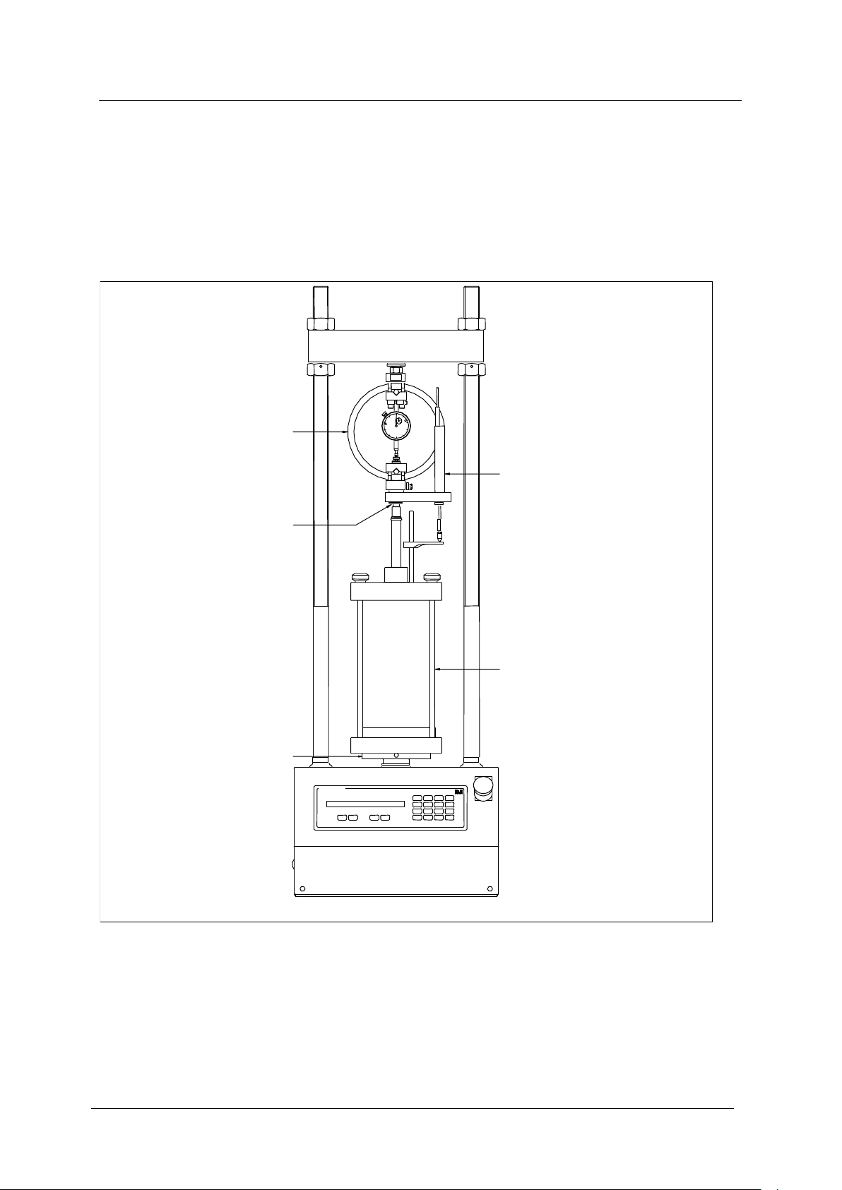
5 Setting up for CBR tests
Load ring
Penetration
piston
Platen adaptor
Surcharge
weights
Stabilising bar
CBR Mould
Figure 3. Typical CBR test set up
Platen
Penetration
dial gauge
Original Instructions 10

5.1 Refer to the relevant standard for full details of the CBR test procedure.
5.2 A typical set up for carrying out a CBR penetration test is shown in figure 3.
5.3 The correct location of the CBR mould is achieved by interposing the platen adaptor
(supplied with the Multiplex 50) between the machine platen and the mould.
5.4 It is suggested that the test should be started with the platen set approximately 10
mm up from its lowest position.
5.5 Position the crosshead at the height required by firstly slackening the nuts on either
side of the crosshead and then adjust the crosshead to the required height by using
the adjustment nuts below the crosshead. To ensure that the crosshead is level, the
alignment studs on the lower nuts should be located centrally and at the front of the
machine. Tighten the locking nuts using a spanner.
5.6 To ensure stability and central location of the penetration piston, the stabilising bar
must always be used. When using the maximum number of surcharge weights, it may
be necessary to clamp the stabilising bar to the threaded part of the columns. In this
case it is recommended that packing pieces (i.e. aluminium strips) be placed between
the stabilising bar clamp screws and the column threads.
5.7 With all the equipment correctly located and secured in the machine, press the UP
key to close most of the daylight. See 4.6
5.8 Set the speed according to the standard specified. Press the RUN key to commence
the test.
5.9 At the completion of the test, press the STOP key.
5.10 Press the DOWN key to return the platen to its lowest position or until the STOP key
has been pressed when the platen has descended the required distance.
Original Instructions 11
6 Setting up for Marshall tests
Load ring
Ball nipple
removed from
load ring
Stabilising bar
Load stud
Breaking Head
Platen
Figure 4. Typical Marshall test set up
Adaptor supplied
with the
Stability piston
Stability piston
Original Instructions 12
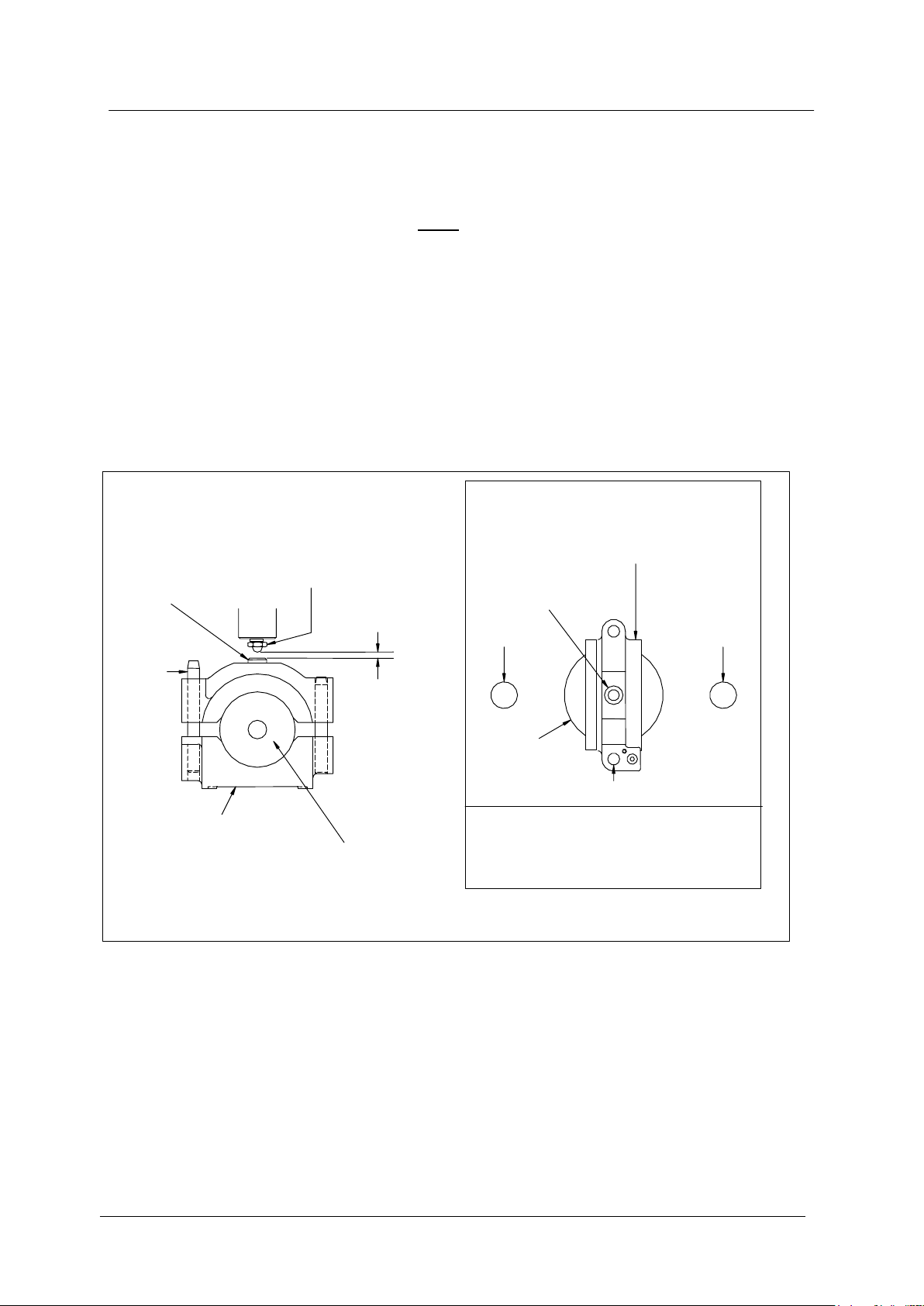
6.1 Refer to the relevant standard for full details of the Marshall test procedure.
6.2 A typical set up for carrying out a Marshall test is shown in figure 4.
Important: the Stability piston and Stabilising bar should be used as shown in
figure 4 and the breaking head must be placed in the machine with the long
guide post facing the operator as shown in figure 5 to ensure very safe loading
conditions.
6.3 To fit the Stability piston, remove the ball nipple from the load ring (or load
transducer) and replace it with the adaptor supplied with the Stability piston. Fit the
ball nipple removed from the load ring (or load transducer) onto the Stability piston
and then screw the Stability piston onto the adaptor on the load ring (or load
transducer). Ensure that all connections are fully tightened.
6.4 Before commencing tests it is necessary to set the height of the crosshead to obtain
the optimum clearance between the ball nipple and the load stud on the Breaking
head. See figure 5.
6.5 Ensure that the Stabilising bar is in position before commencing the test. It is
important to set the Stabilising bar at a height that will not impede the raising of the
platen and Breaking head.
6.6 Operate the machine so that the platen travels to its lowest position.
With the Breaking head on the platen, fit the calibration disc. See figure 5
Important: do not under any circumstances load the machine with the
calibration disc in position.
6.7 Position the crosshead to give the clearance shown in figure 5. To ensure that the
crosshead is level, the alignment studs on the lower nuts should be located centrally
and at the front of the machine. Tighten the locking nuts using a spanner.
column
column
load stud
breaking head
rear of machine
platen
long guide post
front of machine
view from above showing position
of breaking head on the platen
5 mm minimum
long
guide
post
load stud
ball nipple
view showing clearance between
ball nipple and load stud
Figure 5
calibration disc
breaking head
Original Instructions 13
6.8 It should be possible to remove and replace the Breaking head complete with its
sample without disturbing the ball nipple.
6.9 Set the speed according to the standard specified. Press the RUN key to commence
the test.
6.10 At the completion of the test, press the STOP key and return the platen to its lowest
position.
7 Setting up for Quick Undrained Triaxial tests
Axial strain transducer
Extended ball nipple
Load ring
Triaxial cell
Platen
Figure 6. Typical Quick Undrained Triaxial test set up
(see note below)
PLEASE NOTE: The displacement transducer shown in the diagram can only be
7.1 Refer to the relevant standard for full details of the Quick Undrained Triaxial test
procedure.
connected to a DSU readout unit.
Original Instructions 14

8 Maintenance
8.1 After each series of tests raise the platen to its maximum height and clean the platen
and case removing all debris, spots of binder etc., particularly from under the platen.
8.2 Apply a smear of medium grease to the shaft under the platen where it runs into the
base casting. This is particularly important where a solvent is used for cleaning in this
area.
8.3 After a prolonged period of use, or at least annually, the following internal
maintenance should be carried out.
8.4 Remove the load measuring device from the crosshead. Raise the platen to its
maximum height.
Warning: always disconnect the machine from the power supply before carrying out
maintenance work or making any adjustment.
8.5 Using the tommy bar provided, unscrew the platen from the jacksleeve
(anticlockwise).
8.6 Remove the two screws at the front and the six screws at the rear of the machine. Lift
the case evenly up the columns. A smear of grease on the columns will assist the
grommets to slide smoothly. Caution:Take care as the case can be raised only a
limited amount before being restrained by connecting cables. Support or suspend the
case as convenient or totally remove the crosshead and case. If the case is to be
removed, then firstly disconnect the ribbon type cables from the keypad & display
from the microprocessor PCB, the cable from the Emergency Stop switch from the dc
drive PCB and the earthing lead. It is crucial that all connectors are replaced in the
correct orientation –make a note of their position before disconnecting them.
8.7 Check for any undue play in the
drive belt. If there is, slacken the
four screws holding the motor to
the main casting. Slide the whole
motor assembly until the belt is just
taut.
8.8 Check the alignment of the pulleys
by laying a steel rule across their
faces. Retighten the fixing screws.
(see figure 7)
8.9 If the belt shows any signs of
cracking, fretting or other signs of
wear, it must be replaced
immediately.
8.10 Inspect the tacho-generator drive
belt for signs of wear and replace if
necessary. (see figure 7).
jacksleeve
align pulleys
Figure 7
Motor fixing screws
tacho-generator
electric motor
drive belt
8.11 Refit the case ensuring that any disconnected wires have been reconnected and do
not foul on the drive mechanism. Replace the case fixing screws. Lift the front panel
back into position and replace the fixing screws.
8.12 Screw the platen back onto the jacksleeve and tighten with the tommy bar.
Original Instructions 15

9 Connecting a DSU Readout device
9.1 Multiplex 50 machines fitted with transducers (instead of manual gauges) may be
connected to a transducer readout device called a DSU. This device allows real-time
display of transducer readings and storage of test data, which can then be
downloaded to a PC. The DSU also provides several other features such as
automatic overload shut-off, automatic logging start, automatic checking of speed
selection and peak force / displacement display.
There are 2 DSU connections on the rear –one provides a serial link (9 way RS232
connector) and the other provides machine identification and remote shut-off
functions (round connector). The default serial port speed is 19200 baud. Please
see DSU manual.
Original Instructions 16

DIRECTIVE ON WASTE ELECTRICAL & ELECTRONIC EQUIPMENT (WEEE)
Table of contents


