Shel lab SMI Series User manual

MICROBIOLOGICAL INCUBATORS
SMI FAMILY
Installation - Operation Manual
SMI2sSMI6sSMI7sSMI11sSMI12s

2 | Page
Pictured on the front cover, left to right: SMI2, SMI6, SMI7, SMI11, SMI12
Note: The SMI12 and SMI12-2 incubators each require two power outlets to plug into.
The SMI2, SMI6, SMI7, SMI11, and SMI12 incubators require 100 – 120-volt NEMA 5-15R power outlets.
The SMI2-2, SMI6-2, SMI7-2, SMI11-2, and SMI12-2 incubators require 220 – 240-volt CEE 7/7
power outlets.
Warning:This product contains chemicals, including triglycidyl isocyanurate, known to the State of
California to cause cancer as well as birth defects or other reproductive harm. For more information,
go to www.P65Warnings.ca.gov.
¡Advertencia! Este producto contiene sustancias químicas, incluido el triglicidil isocianurato, que el
estado de California sabe que causa cáncer, así como defectos de nacimiento u otros daños
`reproductivos. Para obtener más información, visite www.P65Warnings.ca.gov.
Avertissement!Ce produit peut vous exposer à des produits chimiques, dont l'isocyanurate de
triglycidyle, reconnu par l'État de Californie pour provoquer le cancer, des anomalies congénitales
ou d'autres problèmes de reproduction. Pour plus d'informations, visitez le site
www.P65Warnings.ca.gov.

3| Page
SMI Microbiological Incubators
100 – 120 Voltage Models: SMI2 SMI6 SMI7 SMI11 SMI12
220 – 240 Voltage Models: SMI2-2 SMI6-2 SMI7-2 SMI11-2 SMI12-2
Part Number (Manual): 4861825
Revised: June 15, 2021
Sheldon Part ID Numbers:
Model SMI2 SMI6 SMI7 SMI11 SMI12
Part ID SLM222 SLM622 SLM722 SLM1122 SLM1222
Model SMI2-2 SMI6-2 SMI7-2 SMI11-2 SMI12-2
Part ID SLM222-E SLM622-E SLM722-E SLM1122-E SLM1222-E
The Part ID denotes the build type of the model. The manufacturer periodically releases new build-type
designs incorporating new features and refinements of existing ones.

4 | Page
TABLE OF CONTENTS
MODEL CERTIFICATIONS......................................................................................................................................7
Electromechanical Safety Testing..................................................................................................................................... 7
CE Compliant........................................................................................................................................................................... 7
ISO Certified Manufacturer.................................................................................................................................................. 7
INTRODUCTION..................................................................................................................................................... 9
Read this Manual....................................................................................................................................................................9
Safety Considerations and Requirements ......................................................................................................................9
Contacting Assistance ........................................................................................................................................................ 10
Manufacturing Warranty .................................................................................................................................................... 10
Engineering Improvements ............................................................................................................................................... 10
Reference Sensor Device ................................................................................................................................................... 11
RECEIVING YOUR UNIT....................................................................................................................................... 13
Inspect the Shipment........................................................................................................................................................... 13
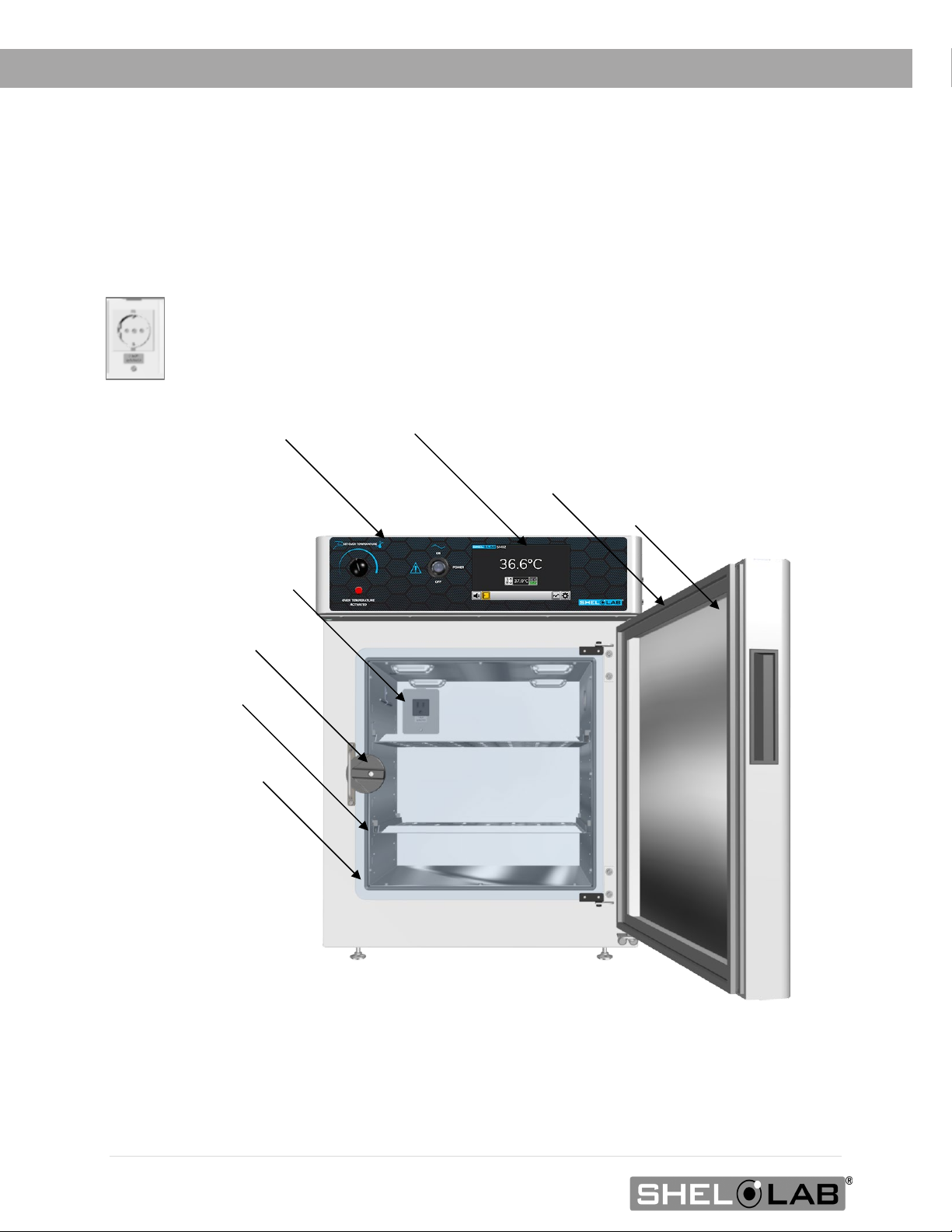
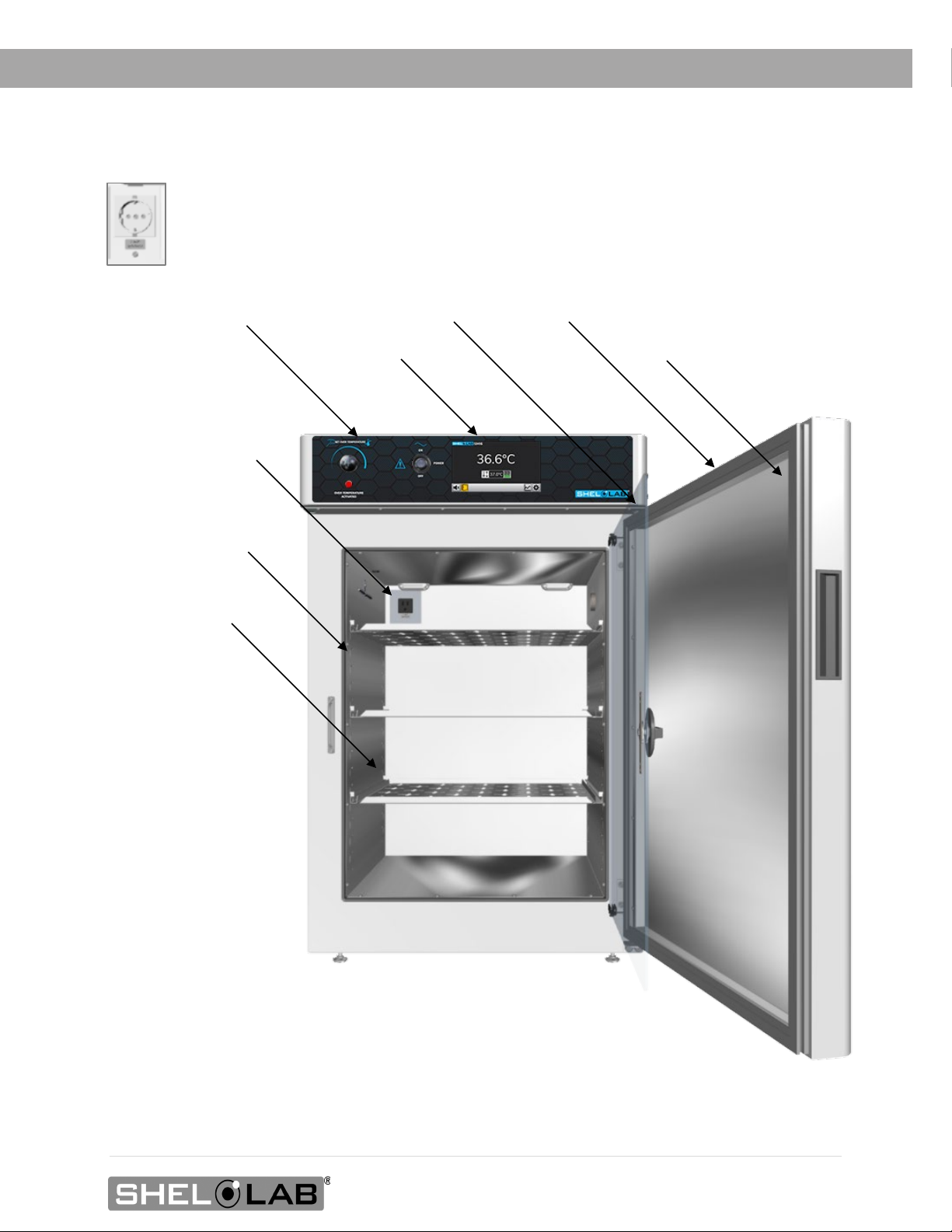
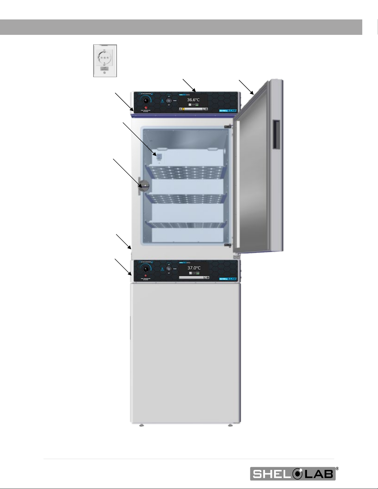
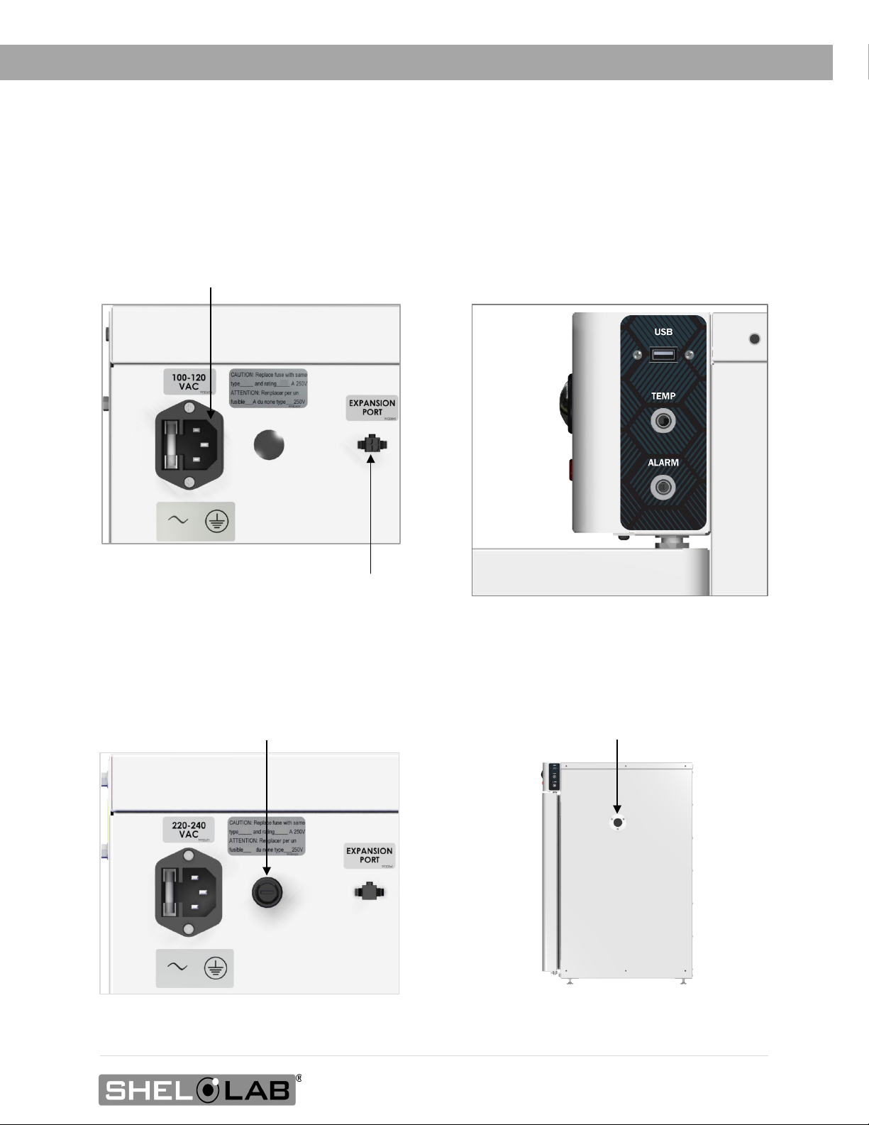
Orientation Images .............................................................................................................................................................. 14
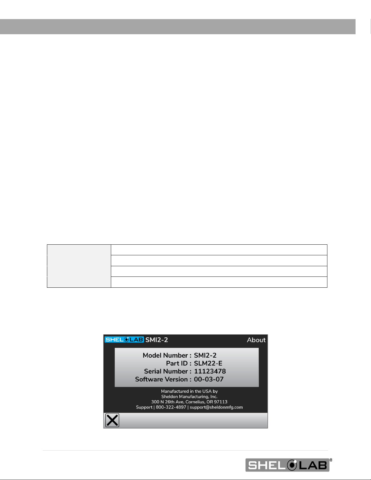
Recording Data Plate Information.................................................................................................................................. 20
INSTALLATION......................................................................................................................................................21
Installation Procedures Checklist .................................................................................................................................... 21
Required Ambient Conditions.......................................................................................................................................... 22
Required Clearances.......................................................................................................................................................... 22
100 – 120 Volt Power Requirements.............................................................................................................................. 23
220 – 240 Volt Power Requirements............................................................................................................................ 24
Lifting and Handling ........................................................................................................................................................... 25
Removing from the Pallet.................................................................................................................................................. 25
Leveling.................................................................................................................................................................................. 25
Install the Incubator ............................................................................................................................................................ 26
Deionized and Distilled Water......................................................................................................................................... 26
Installation Cleaning and Disinfection .......................................................................................................................... 26
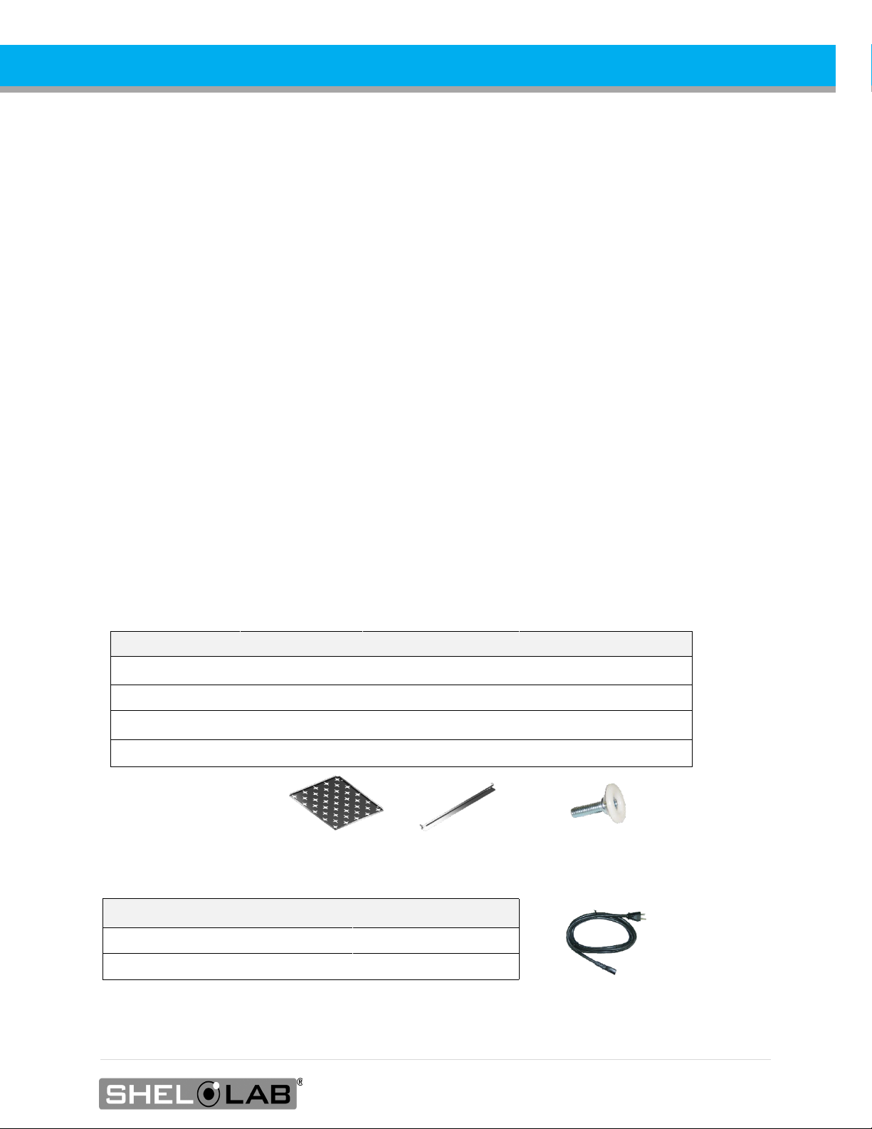
Install the Shelving...............................................................................................................................................................27
Access Port ............................................................................................................................................................................27
GRAPHIC SYMBOLS............................................................................................................................................ 29
CONTROL OVERVIEW.......................................................................................................................................... 31
OPERATION.......................................................................................................................................................... 33
Theory of Operation ........................................................................................................................................................... 33
Put the Incubator into Operation .................................................................................................................................... 34
Set the Date and Time....................................................................................................................................................... 35
Adjust the Temperature Setpoint ................................................................................................................................... 36
Adjusting The Temperature Deviation Alarm ..............................................................................................................37
Set the Over Temperature Limit (OTL).......................................................................................................................... 38
Passcode Locking the Settings ....................................................................................................................................... 39
Changing Locked Settings ............................................................................................................................................... 40
Alarms and Muting............................................................................................................................................................... 41
Loading Samples................................................................................................................................................................. 42
Chamber Power Outlet...................................................................................................................................................... 42
Power and Memory............................................................................................................................................................. 43
Data Log ................................................................................................................................................................................ 43
Data Log Copy and Export............................................................................................................................................... 44
Real Time Data Outputs.................................................................................................................................................... 46
Accessory Expansion Port ................................................................................................................................................ 46
Humidifying the Incubator................................................................................................................................................. 46
Condensation and the Dew Point ...................................................................................................................................47
USER MAINTENANCE ......................................................................................................................................... 49
Cleaning and Disinfecting................................................................................................................................................. 49

5| Page
Minimizing Contamination Exposure .............................................................................................................................. 51
Storing the Incubator........................................................................................................................................................... 51
Door Components................................................................................................................................................................ 51
Electrical Components........................................................................................................................................................ 51
Calibrating the Temperature Display ............................................................................................................................ 52
UNIT SPECIFICATIONS....................................................................................................................................... 57
Weight......................................................................................................................................................................................57
Dimensions.............................................................................................................................................................................57
Capacity ................................................................................................................................................................................. 58
Shelf Capacity by Weight.................................................................................................................................................. 58
Temperature ......................................................................................................................................................................... 58
Power...................................................................................................................................................................................... 59
PARTS LIST............................................................................................................................................................61

6 | Page
TABLE OF CONTENTS

7| Page
MODEL CERTIFICATIONS
Model Certification and Compliance Statements
ELECTROMECHANICAL SAFETY TESTING
61010 Safety Certified: Canada, USA, EU
Electrical, mechanical, and fire hazards
The models in this manual are CUE listed by TÜV SÜD America as incubators for
professional, industrial, or educational use in conditions in which no flammable,
volatile, or combustible materials are being heated and the unit is being operated
under an environmental air pressure range of 22.14 – 31.3 inHg (75 – 106 kPa).
These models have been tested to the following requirements:
CAN/CSA C22.2 No. 61010-1:2012
CAN/CSA C22.2 No. 61010-2-010 + R:2009
UL 61010A-2-010:2002
UL 61010-1:2012
EN 61010-1:2010
EN 61010-2-010:2003
TÜV SÜD America, Inc. is a Standards Council of Canada accredited certification
body, an OSHA-recognized NRTL, and an EU Notified Body.
CE COMPLIANT
These unit models meet all required electromagnetic compatibility (EMC),
EU low-voltage, and RoHS directives.
ISO CERTIFIED MANUFACTURER
SHEL LAB is a brand of Sheldon Manufacturing, INC, an ISO 9001
certified manufacturer.

8 | Page
CERTIFICATIONS

9| Page
INTRODUCTION
Thank you for purchasing a SHEL LAB incubator. We know you have many choices in today’s
competitive marketplace when it comes to constant temperature equipment. We appreciate you
choosing ours. We stand behind our products and will be here if you need us.
READ THIS MANUAL
Failure to follow the guidelines and instructions in this user manual may create a protection impairment
by disabling or interfering with the unit safety features. This can result in injury or death.
Before using the unit, read the manual in its entirety to understand how to install, operate, and maintain
the unit in a safe manner. Ensure all operators are given appropriate training before the unit begins
service.
Keep this manual available for use by all operators.
SAFETY CONSIDERATIONS AND REQUIREMENTS
Follow basic safety precautions, including all national laws, regulations, and local ordinances in your area
regarding the use of this unit. If you have any questions about local requirements, please contact the
appropriate agencies.
SOPs: Because of the range of potential applications this unit can be used for, the operator or their
supervisors must draw up a site-specific standard operating procedure (SOP) covering each application
and associated safety guidelines. This SOP must be written and available to all operators in a language
they understand.
Intended Applications and Locations: The incubators are intended for constant temperature, non-
humidified microbiological incubation applications in professional, industrial, and educational
environments. The units are not intended for use at hazardous or household locations.
Power: Your unit and its recommended accessories are designed and tested to meet strict safety
requirements.
•The unit is designed to connect to a power source using the specific power cord type
shipped with the unit.
•Always plug the unit power cord into a protective earth grounded electrical outlet
conforming to national and local electrical codes. If the unit is not grounded properly, parts
such as knobs and controls can conduct electricity and cause serious injury.
•Do not bend the power cord excessively, step on it, or place heavy objects on it.
•A damaged cord can be a shock or fire hazard. Never use a power cord if it is damaged or
altered in any way.
•Use only approved accessories. Do not modify system components. Any alterations or
modifications to your unit not explicitly authorized by the manufacturer can be dangerous
and will void your warranty.

10 | Page
INTRODUCTION
CONTACTING ASSISTANCE
Phone hours for Sheldon Customer Support are 6 am – 4:30 pm Pacific Coast Time (west coast of
the United States, UTC -8), Monday – Friday. Please have the following information ready when
calling or emailing Customer Support: the model number, serial number, part number, and part ID
(see page 20).
1-800-322-4897 extension 4
(503) 640-3000 extension 4
FAX: (503) 640-1366
Sheldon Manufacturing, INC.
P.O. Box 627
Cornelius, OR 97113
USA
MANUFACTURING WARRANTY
For information on your warranty and online warranty registration please visit:
sheldonmanufacturing.com/warranty
ENGINEERING IMPROVEMENTS
Sheldon Manufacturing continually improves all of its products. As a result, engineering changes and
improvements are made from time to time. Therefore, some changes, modifications, and
improvements may not be covered in this manual. If your unit’s operating characteristics or
appearance differs from those described in this manual, please contact your SHEL LAB dealer or
customer service representative for assistance.

11 | Page
INTRODUCTION
REFERENCE SENSOR DEVICE
Must be purchased separately
Temperature Calibrations
If you are not using a third-party service, a reference sensor device is required for calibrating
your unit’s temperature display.
•See the Calibrating the Temperature Display procedure on page 52 for more information.
Device Accuracy
Reference devices must meet the following standards:
•Accurate to at least 0.1°C
The device should be regularly calibrated, preferably by a third party.
Temperature Probe
Use a digital device with a wire thermocouple probe that can be introduced into the unit chamber
through the access port or door space. Select a thermocouple suitable for the application temperature
you will be calibrating at.
Why a Probe?
Reference readings taken from outside the chamber using wire temperature probes avoid chamber
door openings. Openings disrupt the chamber temperature. Each disruption requires a minimum 1-hour
wait to allow the chamber to re-stabilize before continuing.
No Alcohol or Mercury Thermometers
Alcohol thermometers do not have sufficient accuracy to conduct accurate temperature calibrations.
Never place a mercury thermometer in the unit chamber. Always use thermocouple probes.
Temperature
Reference

12 | Page
INTRODUCTION

13 | Page
RECEIVING YOUR UNIT
INSPECT THE SHIPMENT
Safe delivery becomes the responsibility of the carrier when a unit leaves the factory. Damage
sustained during transit is not covered by the manufacturing defect warranty.
When you receive your unit, inspect it for concealed loss or damage to its interior and exterior. If you
find any damage to the unit, follow the carrier’s procedure for claiming damage or loss. Save the
shipping carton until you are certain that the unit and its accessories function properly.
1. Carefully inspect the shipping carton for damage.
2. Report any damage to the carrier service that delivered the unit.
3. If the carton is not damaged, open the carton and remove the contents.
4. Inspect the unit for signs of damage. Use the orientation images in this chapter as
references.
5. The unit should come with an Installation and Operation Manual.
6. Verify that the correct number of accessory items has been included.
7. Carefully check all packaging for accessory items before discarding.
Included Accessories
Model Shelves Shelf Mounts Leveling Feet
SMI2s, SMI7s 2 4 4
SMI6s 3 6 4
SMI11s 6 12 4
SMI12s 6 12 4
Power Cords
Model Number of Cords
SMI2s, SMI6s, SMI7s, SMI11s
1
SMI12s
2

14 | Page
RECEIVING
ORIENTATION IMAGES
Control Panel
Control Panel Touch Display
SMI2 Chamber Power Outlet,
NEMA 5-15R 100 – 120 Volt*
Chamber Inner Door Latch
SMI2s
Chamber Outer Door
Incubation Chamber
Outer Door Seal
Chamber Inner Door Seal
Data Plate
*SMI2-2 Chamber Power Outlet, CEE7 220 – 240 Volt

15 | Page
RECEIVING
Control Panel
SMI6 Chamber Power Outlet,
NEMA 5-15R 100 – 120 Volt*
SMI6s Front
Chamber Outer Door
Incubation Chamber
Chamber Inner Door
Outer Door Seal
Chamber Inner Door Seal
Data Plate
Touch Display
*SMI6-2 Chamber Power Outlet, CEE7 220 – 240 Volt

16 | Page
RECEIVING
Control Panel
SMI7 Chamber Power Outlet,
NEMA 5-15R 100 – 120 Volt*
SMI7s
Chamber Outer Door
Chamber Inner
Door Latch
Touch Display
Outer Door Seal
Chamber Inner
Door Seal
Data Plate
*SMI7-2 Chamber Power Outlet, CEE7 220 – 240 Volt

17 | Page
RECEIVING
Chamber Inner Door – Left
SMI11s Front
Chamber Outer Door – Right
SMI11 Chamber Power Outlet, NEMA 5-15R 100 – 120 Volt*
Chamber Outer Door – Left
Note: The SMI11 has a single incubation chamber.
Chamber Inner Door – Right
Control Panel
Outer Door Seal
Data Plate (interior)
Inner Chamber Door Seal
*SMI11-2 Chamber Power Outlet, CEE7 220 – 240 Volt

18 | Page
RECEIVING
Chamber Inner Door Latch
SMI12 Chamber Power Outlet,
NEMA 5-15R 100 – 120 Volt*
SMI12s
Chamber Outer Door Seal
SMI12 Data Plate
Note: The SMI12 consists of two SMI6 incubators secured to a stacking brace. Each incubator
operates independently and is separately powered.
Bottom Incubator
Top Incubator
Top Incubator Control Panel
Bottom Incubator Control Panel
Touch Display
*SMI12-2 Chamber Power Outlet, CEE7 220 – 240 Volt

19 | Page
RECEIVING
Sides – All Models
Left Side – 100 to 120 Volt Incubators
Power Cord Inlet with Fuse
Holder (Fuse Holder Cover
Removed)
Data Ports
Right Side
Chamber Access Port
24-volt Expansion Port for SHEL LAB Accessories
Fuse Holder for Second Fuse
Left Side – 220 to 240 Volt Incubators

20 | Page
RECEIVING
RECORDING DATA PLATE INFORMATION
Record the unit model number, serial number, part number, and part ID below for future reference.
Customer Support needs this information to provide accurate help during support calls and emails.
•SMI2s, SMI6s, SMI7s
oThe data plate is located on the inside of the incubation chamber door in the top
right corner.
•SMI11s
oThe data plate is located on the inside of the right-hand chamber door in the top
right corner.
•SMI12s
oThe data plate is located on the exterior, left side of the incubator, on or just above
the mounting brace.
MODEL NO:
SERIAL NO:
PART NO:
PART ID:
•The Model Number, Part ID, and Serial Number can also be found on the About screen in
the settings menu.
Other manuals for SMI Series
1
This manual suits for next models
5
Table of contents
Other Shel lab Laboratory Equipment manuals