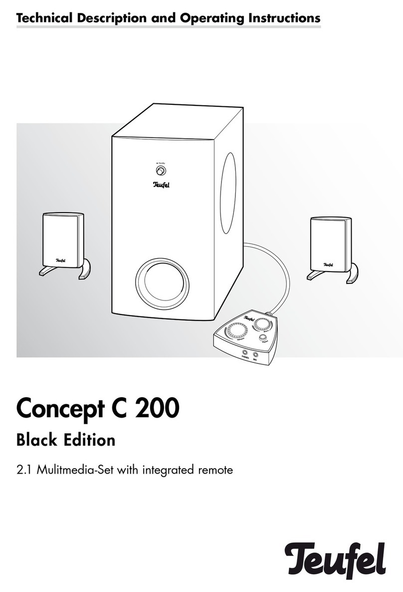
Teufel hulsta User manual

SEITE 1
1544447
SERVICE
hülsta-werke · Karl-Hüls-Straße 1 · 48703 Stadtlohn
TEL +49 2563 86-1500 · FAX +49 2563 86-1417
Stand: 02/2014
Have fun with your new Teufel sound furniture!
Now just connect TV and playback devices and let‘s go!
For more information - for example, how to upgrade to 5.1 surround sound
- See www.Teufel.de / huelsta
450x100x380mm ( BxHxT)

SEITE 2
Safety notes
CONTENTS
3-4
Control unit 5
Controls and
connections
Remote control unit 6
Subwoofer 7
Remote control unit Inserting batteries 8
Functions 8
Connections
Control unit Antennas 9
Input jacks for playback sources 10
Outputs 11-12
Connections
subwoofer Input 13
Satellite loudspeakers 13
Switchingonandoff 14
Adjust subwoofer
Automa.Switching on and off 14
Auto On Level 14
Subwoofervolume 14
Switching on and off 15
Basic functions
Select source 15
Adjusting the volume 16
Menu functions Surround menu 18
“Tonecontrol” menu 18
“Speaker Levels” menu 18
“Sourcelevels”menu 19
„Audio mapping“ menu 19
“Speaker Setup” menu 19
“SystemSetup“menu 19
Special function
buttons Surround 21
Test tone 21
Channel level buttons 21
Dimmer 21
Equalizer 21
Menu functions Controls 17
“Tuner” menu 17-18
Tone/LipSync 22
Direct 22
Info 22
Sleep 22
Radio playback Setting radio stations 23
Station memory 23-24
Troubleshooting 25-26
27
Care and cleaning
Environmental protection
28
Technical data
Mainsconnections 14

SEITE 3
Safety notes
Signal symbols
The following signal symbols can be found
in this instruction manual:
Danger
High risk!
Failure to observe the warning may
result in personal injury or death.
Caution
Moderate risk!
Failure to observe the warning may
result in property damage.
Minor risk!
Points which should be observed
when handling the unit.
Safety notes
Danger
Danger of electric shock!
Deficient electrical installation or
excessive mains voltage may result
in an electrical shock:
• Please ensure that the correct voltage is
in use when connecting the unit.
The subwoofer and the power unit
for the control device are intended for
mains voltage of 230 V ~ / 50 Hz
• Please only use the power unit supplied
with the operating device.
• Disconnect the power unit or the plug
immediately and discontinue using the
device if any part emits smoke, smells of
burning, or creates unusual noises, if the
housing or the power unit is defective or
if any other kind of damage is visible.
• • The operating switch for the control
device does not disconnect the unit from
the mains supply. To do this, please
use (if present) the mains switch on the
sound box or disconnect the mains plug.
• Never open up the housing of a device
or its power supply unit. Units may only
be repaired by authorised personnel.
Only parts which conform with the origi-
nal device specifications may be used
for repairs. In this unit there are electri-
cal and mechanical components which
are essential in order to avoid exposure
to sources of danger.
• Please only use the unit indoors.
• Do not use the units in moist rooms, and
protect them from dripping or spraying
water. Please also make sure that no
vases or other containers with fluid are
placed on the unit or in its vicinity, so
that no fluids can enter the housing or
the power supply unit. If water or any
other foreign objects penetrate the
housing, immediately disconnect the
mains plug and have the unit inspected
by qualified personnel.
• Never touch the mains plug or the power
supply unit with damp hands.
• Check the unit regularly for damage.
Danger
Danger to children!
Children can become trapped in the
packing film when playing and be
suffocated.
• Do not allow children to play with the
unit or the packing film. There is a
danger of suffocation.
• Please ensure that children do not
remove any small parts from the unit or
pull them off. (e.g. control knobs or plug
adapters). They might swallow the parts
and choke. Never allow children to use
electrical devices unsupervised.
Danger to hearing!
Loud noise may lead to hearing
loss.
Very high noise pressure may be produ-
ced particularly when a unit/subwoofer is
switched on and turned up to full volume.
This may have psychological conse-
quences and also cause physical injury.
Children and pets are particularly at risk.
• Set the volume to a low level.
• Keep a safe distance away from the
unit when the volume level is high and
never place your ears directly next to the

SEITE 4
loudspeakers.
• Prevent damage to your health by avoi-
ding extended listening at high volume.
Danger
Danger of chemical burns!
Leaking battery acid may lead to
chemical burns
• Do not allow battery acid to come into
contact with skin, eyes or mucous mem-
branes. In case of contact with acid,
rinse the affected parts immediately with
plenty of plain water and if necessary
see a doctor.
Danger
Risk of injury/damage
Incorrect location may result in
damage.
• Never use the unit unmounted in vehi-
cles, in instable locations, on wobbly
tripods or furniture, on underdimensio-
ned brackets etc. The unit could tip or
fall down and cause injury to persons or
be damaged itself.
• Place the unit so that it cannot be
inadvertently knocked over and make
sure that the cables do not pose a trip
hazard.
• Do not place the unit near sources of
heat (e.g. radiators, ovens or other heat
generating equipment such as amplifiers
etc.)
•
Fire hazard!
Improper use of the unit may lead to
damage or fire.
• Do not place open flames such as
burning candles or similar on the unit.
• Ensure sufficient ventilation.
• Do not place the unit in direct sunlight.
• Do not cover the vents with curtains,
blankets, newspapers or similar. Heat
build up inside can shorten its lifetime.
Danger
Risk of damage!
Power overload due to lightning
strike
may damage or destroy the unit.
• If the unit is to be left unsupervised for a
long period (e.g. during a holiday), or if a
thunderstorm is forecast, disconnect the
plug from the mains supply.
Gefahr
Notes on separate multiple
sockets
• hülsta Type 291 / 292 : Max. Load
2300 watts / 10A
• The power strips do not put behind
each other!
• Do not cover multiple sockets
when in use!
• Electrical parts are without voltage when
the power plug is pulled!
• Ensure mains plug is a cessible
at all times!
• Only for use in enclosed rooms!
Danger

SEITE 5
Controls and connections
Control unit Front side
Rear side
No. Name Description
1 SOURCE Change signal source
2– Display panel
3 POWER/
SELECT Control dial/switch on
button
4 BACK Return button
No. Name Description
5FM Connector jack for
VHF antenna
6 AM +/
GND Connector jacks for
medium wave antenna
7 SERVICE USB connection (only for
service)
8 OPTICAL Digital audio input
jack for optical cables
9 COAXI-
AL 1/2 Digital audio input jacks
for coaxial cables
10 LINK Connector jack for addi-
tional expansions
11 AUX 1 Analogue audio input
jack (3.5-mm plug)
12 AUX 2/3 Analogue audio input
jacks (Cinch)
13 HEAD-
PHONE Connector jack for
headphones
14 RC/PRE
OUT Analogue audio output
(stereo downmix)
15 SURR,
SUB,
CENTER,
FRONT
5.1 Audio output jacks
16 GND Ground connection
17 HDMI
OUT HDMI output jack
18 HDMI IN
1 – 3 HDMI input jacks
19 12V Connector jack for
power supply unit
1324
56 78910111213 1415
16171819

SEITE 6
Remote control unit
No. Name Description
20 SLEEP Sleep function
21 HDMI 1
– 3
OPTICAL
COAXI-
AL 1/2
AUX
1/2/3
FM/AM
Select input source
22 1 ... 0 Number buttons
23 FREQU. Radio mode: enter
tuning frequency
24 Mute loudspeakers
25 VOL +/– Adjust volume
26 TONE/
LIPSYNC Adjust sound,
set sound delay
27 Arrow buttons
28 RETURN Return button
29 MODE Switch between mono
and stereo during radio
mode
30 MEM Set station memory
31 LEVEL
+/– Set channel level
32 CH SEL Select channel for setting
level
33 TEST Switch test sound on/off
34 DIMMER Select display panel
brightness
35 DIRECT Emit direct sound (no
sound adjustment)
36 INFO Display format of sound
signal
37 • Select button
38 EQUALI-
ZER Adjust sound in nine
frequency ranges
39 CH +/– Radio mode: select
station memory
40 SUR-
ROUND Change surround mode
41 PRESET Radio mode: select
station memory
42 Switch on control unit or
place in stand-by
20
21
22
23
24
26
27
28
36
37
38
39
40
41
29
35
30
34
32 31
33
42
25

SEITE 7
No. Name Description
43 LINE IN Analogue 5.1 audio
input jacks
44 AUTO ON
LEVEL Set sensitivity level for
automatic switch on
45 SUBWO-
OFER
VOLUME
Subwoofer volume
control
46 POWER
MODE
Automatic switch on/off
or switch on long-term
47 – Control LED
48 SPEAKER Output jacks for
satellite loudspeakers
49 POWER
ON/OFF Mains switch
50 – Connector jack for
mains cable
51 – Safety fuse holder
43 44 45 46 47
48
50
51
49
Subwoofer Rear side

SEITE 8
Remote control unit
To operate the remote control unit you re-
quire two batteries, type micro or AAAsize
with 1.5 volts (supplied).
Insert batteries
• Press lightly on the arrow on the lead
of the battery compartment on the rear
of the remote control and push the lid
downwards and out.
• Remove any old batteries (please follow
the notes on disposal on page 27).
• Insert the batteries in the battery com-
partment as shown in the illustration.
• Replace the lid on the compartment and
push to close.
Functions
The remote control unit transmits
its signals by infrared light. So it is
necessary that the remote control unit
points in the direction of the control unit.
The infrared receiver is on the front side.
Please ensure that the infrared light is not
obstructed by any objects.
The cover of the sound box allows
infrared light to permeate.

SEITE 9
Connections Control unit
Danger
Risk of injury/damage!
Arrange the cables so that they do
not pose a trip hazard.
Antennas
Danger
Risk associated with lightning
strike!
If you use outdoor or a roof anten-
nas, be absolutely sure that the antenna
has lightning protection.
FM/VHF antenna
Connect the antenna for receiving FM/
VHF channels to jack 5 “FM”.
This may be a roof/outdoor antenna
or a cable TV connection. To do so you
require a coaxial connector
cable.
If no antenna connection is available
on site, you can use the cable antenna
supplied. Insert the antenna plug into jack
5 “FM” and alter the position of the
cable antenna until reception is best.
Then fix the antenna in position.
AM/MW antenna
Use the antenna supplied to receive
medium wave channels (AM/MW).
This antenna can be placed anywhere
or screwed on to a (wardrobe) wall.
The connector cable for the antenna
is connected to jacks 6“AM” on the
rear side of the control unit. Press down
the lever on each of the connector
terminals and insert the end of the cable in
the opening above it. Releasing the lever
locks the cable in place.
5
6

SEITE 10
Input jacks for playback sources
The control unit provides you with three
HDMI inputs for digital audio/video
signals (“HDMI” 1, 2 and 3), three
analogue sound inputs (“AUX” 1, 2 and
3) and one optical and two coaxial sound
inputs.
HDMI 1, 2 and 3
You can connect one playback source
with digital picture and sound signals to
each jack 18 (e.g. PC, Blu-ray player
or games console). To do so you require
an HDMI cable.
If a unit does not issue the sound via
HDMI, you can allocate one of the sound
inputs of the control unit to this source in
the menu.
OPTICAL
You can connect the optical digital sound
output of a playback source to jack 8. To
do so you require an optical cable with
a TOSLINK plug. Your playback source
requires either an optical 3.5-mm jack or
again a TOSLINK jack.
COAXIAL 1 und COAXIAL 2
You can connect the coaxial digital sound
outputs of two playback sources to
the jacks 9. To do so you require one
coaxial cable each with cinch plugs.
If the ARC function is activated, the
connection 9“COAXIAL 1” is no longer
available.
AUX 1, 2 and 3
You can connect playback sources with
analogue sound to jacks 11 and 12.
The jack 11 “AUX 1” is a 3.5 mm
plug jack for connecting, e.g., an
MP3 player. The jacks 12
“AUX 2” and “AUX 3” are cinch jacks,
e.g. for connecting a cassette or tape
player. The Bluetooth receiver is connec-
ted to jack 12 “AUX 2”. When connecting a
record player which does not have a
line output, you require a preamplifier.
891112
18

SEITE 11
Output jacks
TV/Beamer
Connect your TV set to jack
17 “HDMI OUT”. To do so you require an
HDMI cable. (from HDMI standard 1.4a)
Audio outputs
Connect your multichannel active
subwoofer and/or active loudspeakers
to the cinch jacks 15. To do so, you
require 3 stereo cinch cables:
FRONT LEFT/
RIGHT Front channels left/
right
CENTER Middle channel
SUB Subwoofer channel
SURR LEFT/
RIGHT Rear channels left/right
Changing from 3.1 to 5.1 mode is done
in the “system conf.” menu (see
“3.1/5.1” on page 20).
RC/Pre Out
The analogue output 14 “RC/PRE OUT”
provides a stereo signal (“stereo downmix”
2.0), for example for transmitting sound
to a second room.
You can connect an extra end amplifier,
active loudspeaker or even a remote
control transmission system these jacks.
To do so you require a stereo cinch cable.
Headphones
You can connect stereo headphones
with a 3.5 mm plug to jack 13 “
Headphones”.
When the headphones are connected,
the end output stages (14 and 15) are
automatically switched off. These can
however be reactivated with button 24
on the remote control unit. So it is possible
to use the control unit with the active
loudspeakers even when the
headphone cables are permanently
plugged in (e.g. when using wireless
headphones where the transmitter re-
mains permanently plugged in).
14
13
17
15

SEITE 12
19
Danger
Risk of injury/damage!
Reduce the loudspeaker volume
before removing the headphones
plug, otherwise the loudspeaker might
emit sound at an unexpectedly high
level. This could injure your ears or
damage the unit.
Mains connections
• Make sure that your end amplifier,
multichannel active subwoofer or the
active loudspeakers are switched off.
• Connect the small plug of the power-
supply unit to jack 19 “12V”.
• Connect the power supply unit to a
mains jack (230 V ~ / 50 Hz).

SEITE 13
48
Subwoofer connections
Input
Connect the LINE IN jacks 43
of the subwoofers, using the cinch cables
supplied, to the 5.1 output jacks
of the control unit.
Satellite loudspeakers
Check correct polarity!
• Connect clips of the same colour.
Otherwise sound quality suffers.
• The leads of the loudspeaker cables are
marked by different colours or shapes.
• On the rear side of the subwoofer you
will find the connection clips 48 for the
satellite loudspeakers.
• Hear you can connect loudspeaker
cables directly or use the optional
banana plugs. In the following we only
describe direct connections.
1. Feed the loudspeaker cables supplied
from the subwoofer to each of the
satellite loudspeakers.Small hint:
Mark the cables at the subwoofer
end – this will help you if you have to
(dis)assemble the unit.
2. Split the single loudspeaker cable at
both ends down to about 30 mm and-
strip about 10 mm of the insolationoff
each cord.
3. Twist the stripped single wire ends
so that no wires are protruding.
Tin-coating is not necessary.
4. Turn the connector terminal anti-
clockwise Until loose. Feed the strip-
ped cable end into the now visible
hole. Close the terminal by turning it
clockwise. The cable has now been
clamped in place.
5. Connect the other end of the loudspe-
aker cable to the satellite loudspeakers
in the same way.
43

SEITE 14
Mains connections
1. Make sure that the mains switch
49 “POWER” on the subwoofer is
switched off (position “OFF”).
2. Connect the mains connection jack
50 to a mains socket using the mains
supply cable.
3. Switch the mains switch 49
“POWER”on the subwoofer to “ON”.
49
50
Adjust subwoofer
Switching on and off
The switch 49 “POWER” switches
the mains supply on or off. When the
subwoofer is switched on the control
LED 47 lights up green. If the subwoofer
is in standby, it lights up red.
Automatic switching on/off
The switch 46 “POWER MODE”
changes the operating mode:
Auto
On: The subwoofer switches itself on,
as soon as an audio signal is
recognised at the input jacks 43
“LINE IN”. If no audio signal is
recognised for some time, the
subwoofer goes into standby
(Standby).
This is the standard setting
for the sound box.
On: The subwoofer is always
switched on.
Auto On Level
With dial 44 “AUTO ON LEVEL”
you can alter the switch sensitivity
of the subwoofer. The further you turn the
dial clockwise, the more sensitive the
Auto-On function becomes. This means
that the subwoofer switches itself on even
if the audio signal is very low.
Subwoofer volume
With dial 45 “SUBWOOFER VOLU-
ME” you can adjust the volume of the
subwoofer relative to the satellite
loudspeakers.
49
43 44 45 46 47

SEITE 15
Basic functions
Switching on and off
If the unit is in standby, a
red point lights up in display panel 2.
• Switch the unit on by briefly pressing the
control dial 3 or button 42 „ “.
If the unit is switched on the letters
in display panel 2 light up.
• Switch the unit back into standby by
pressing the control dial 3or button 42
„“ a little longer.
• After a settable time without activity the
unit automatically switches itself into
standby (see “Autom. switch off” on
page 14).
• The subwoofer automatically switches
itself on and off with the control unit
(see page 14).
Automatic switch-on (CEC)
If your TV set is connected via an HDMI
cable and it supports the CEC
standard, you can activate automatic
switching on and off (see “CEC”, page 19).
Select source
After switching on, the playback source
last selected is activated
• With button 1 “SOURCE” you can chan-
ge
• the playback source in this order:
HDMI 1, HDMI 2, HDMI 3, OPTICAL,
COAXIAL 1, COAXIAL 2, AUX 1,AUX
2 (Bluetooth receiver), AUX 3, FM (VHF
radio, AM (MW radio).
• Or select the playback source directly
with the function buttons 21 on the re-
mote control unit.
The playback source selected is shown
in display panel 2.
21
24
42
25
8
12 3

SEITE 16
Adjusting the volume
• Increase volume: turn control dial 3
clockwise or press button 25 “VOL +”.
• Reduce volume: turn control dial 3anti-
clockwise or press button 25 “VOL -”.
The selected volume is shown
in the section “– – –” (low) up to “10.0
dB” (high) and displayed in the form
of a bar.
Muting (Mute)
• With button 24 „ “you can switch the
loudspeakers off. In display panel 2you
will see the word “MUTE”.
• To switch sound back on: press button
24 „ “ again or alter the volume.
Note: Muting only applies to the
Line outputs — the headphones
output always remains active.

SEITE 17
Menu functions
The functions of the control unit are set
via the menu. This is how to use the
menu:
• Press control dial 3“POWER/SELECT”
or button 37 “•”. The main menu appears
on the connected screen and the display
panel 2.
• Select the required submenu with the
control dial 3 “POWER/SELECT” or ar-
row button 27 „/“ and press control-
dial 3or button 37 “•”.
• The submenu opens and you can
select the next submenu or change the
values with the control dial 3or button
27 „/“.
• Accept the settings by pressing the
control dial 3or button 37 “•” for a short
period.
• With button 4“BACK” or 28 “RETURN”
you can end the relevant function or
abort it and return to previous menu.
If the menu appears in English, you can
change the language for the screen menu
to German (the display panel 2always
shows English texts):
1. Select menu item “SYSTEM SETUP”.
2. Select item “D/E”.
3. Select item “German”.The menu on the
screen now changes to German.
4. Press button 28 “RETURN” until only
the main menu is visible.
“Tuner” menu
This menu is only available in radio
mode (FM/AM).
Station memory (Preset)
Here you can change the station memory
with the control dial 3or the arrow buttons
27 „/“
Frequency
Here you can set the reception frequency
with arrow buttons 27 „
/
“ :
27
28
37
8
234

SEITE 18
• Manually: Every time the button is
touched the frequency is increased or
reduced by one increment.(FM: 0.05
MHz, AM: 9 kHz).
• Automatically: Longer pressing of but-
ton starts station scanning in thedesired
direction, until a programme is found
with a sufficiently goodlevel of reception.
Station search (APS, Auto Tuning)
You can programme station memory slots
automatically. When you see the question
“auto-tuning OK?” briefly press the control
dial 3or select button 37 „•“.The unit will
automatically save the first 30 channels
on VHF/FM or 10 channels on MW/AM.
Already occupied memory slots will be
deleted in the process.
Erase memory (Memory Erase)
Here you can clear station memory slots.
Press select button 37 “•” to erase, or but-
ton 28 “RETURN” to abort.
“Surround” menu
With the control dial 3 or arrow
buttons 27 „/“ you can change the
surround mode for 2-channel sources in
this order:
2.1 Stereo Stereo only via front left/
right and subwoofer
3.1/5.1
Stereo Stereo via all channels
(Upmix)
Dolby PLII
Movie Dolby ProLogic II for
movies
Dolby PLII
Music Dolby ProLogic II for music
DTS NEO:6
Mus DTS NEO:6 for music
DTS NEO:6
Cin DTS NEO:6 for movies
Surr. L / Surr. R are only available in
5.1 mode. (Also see note on page 20,
heading 3.1 / 5.1)
Dolby Digital and DTS (Standard and
HD)
When playing back Dolby Digital or
DTS coded multi-channel tracks the sur-
round mode is preset so that this function
is not operative.
“Tone control” menu
Mode
Dynamic Compression
Dynamic compensation regulates volume
differences between individual tracks on
CDs or other audio sources and ensures
that playback is neither too loud not too
quiet. Possible settings: on, off, auto.
In the „Auto“ setting, the Dynamic
Compression is controlled from the
source, provided that such a „Dolby
TrueHD“ audio track can be output.
Cinema EQ.
This function reduces the percentage of
high tones from the original movie sound
mix to perfectly adapt the sound to the
acoustics of the living room.
Possible settings: on or off or auto
Tone
Here you can adjust the sound (high tones
and bass tones). Possible values: from
–10 dB (decrease) to +10 dB (increase).
Equalizer
With this function very fine adjustments
within 9 frequency ranges are available.
Possible values: each from –20 dB
(decrease) to +6 dB (increase).
The “Reset” menu item resets all frequen-
cy ranges for the selected channel to zero
(neutral).
Note: The equaliser is inactive with some
high definition formats.
“Speaker Levels” menu
Here you can adjust the relative volume
from “–10” (decrease) to “+10” (increase).
It is recommended to use our sound level
meter to optimally adjust the sound level.

SEITE 19
“Source levels” menu
You can adjust the relative volume from
“–10” (decrease) to “+10” (increase) for
each audio source here.
“Audio Mapping” menu
Here you can assign an audio input to
each of the 3 HDMI inputs.
Example: If you would like to connect a
PC without HDMI output: with a DVI-to-H-
DMI adapter you transmit the video signal
while the audio signal is present at one of
the analogue inputs via a cinch cable (e.g.
“AUX 1”).
“Speaker Setup” menu
Phase Sub
This allows you to activate and deactivate
the phase shift (180°) for the subwoofer.
Select the setting with which the subwo-
ofer produces the loudest and clearest
sound.
Lip Sync
Digital image processing in the TV set
requires some time. In order to keep the
image and sound synchronous, delay the
sound by a few milliseconds. Here you
can adjust the audio delay from 0 to
200 ms for each HDMI and other inputs in
order to keep the sound synchronous.
Distance
The surround sound effect may be
corrupted if the speakers are positioned
at different distances to the listening
position. To compensate for these
differences in run time, you can set slight
signal delays for all channels. Measure
the difference from the listening position
to the speakers and enter these values
in the menu. The system calculates the
required delays on this basis.
System Setup menu
HDMI
CEC (Consumer Electronics Control)
If this function has been activated (ON),
CEC compatible devices are controlled
with a control command issued via the
HDMI connection. For example, the
control unit and the connected devices are
automatically activated and deactivated
via the remote control TV set.
ARC (Audio Return Channel)
This option allows audio reception from
the TV via the HDMI cable for TV sets that
support this function. Audio from TV sets
runs to the control unit through the HDMI
cable without having to connect another
cable. If the ARC function is activated, the
9“COAXIAL 1” input is no longer
available.
Possible settings: OFF, ON.
Important!
Please note that many TV sets
only have one HDMI input that
supports the ARC function.
• To use ARC you must also activate
CEC.
Note: if the CEC function is activated,
standby power consumption increases.
Auto-off
After a certain time of inactivity, the device
automatically switches to standby after a
preset time.
Possible values: 60 min. (default),
30 min., never.
Power On Level
Here you can set the volume of your
device when it is activated:
• last: the volume that was set at
deactivating
• fixed (custom): fixed volume from -40 dB
(low) to +10 dB (very loud).

SEITE 20
3.1/5.1
With this you can switch between 3.1 and
5.1 operation.
In 3.1 operation the rear channels are
linked to the front channels and the rel-
evant output jacks 15 “SURR L/R” are
deactivated. This is the standard setting
for the sound box.
In 5.1 operation the rear channels are
projected through the output jacks 15
“SURR L/R”.With the aid of a double cinch
cable you can connect these jacks to the
corresponding input jacks 43 “REAR
LEFT/RIGHT” and operate additional
background loudspeakers (Impedance:
4-8 ohms) via the clips
48 “REAR LEFT/RIGHT”. It is also
possible to use a remote-controlled
transmission system (such as
(e.g. the Teufel RearStation 4).
Note:
Only select 5.1 if corresponding additional
loudspeakers are connected. If 5.1 is
selected without additional loudspeakers,
there is no Surround transmission.
When connecting additional loudspeakers,
the corresponding connection between
the decoder and the subwoofer must be
created.
D/E
You can set the OSD menu language
here. Possible values: German, English
The menu in the unit display panel 2is
always in English.
System Reset
This resets the device to the factory
default.
Table of contents
Other Teufel Stereo System manuals

Teufel
Teufel Concept C 300 WL Manual

Teufel
Teufel Concept C 200 Black Edition Manual

Teufel
Teufel cinebase Manual

Teufel
Teufel MD16 Manual

Teufel
Teufel ROCKSTER Parts list manual

Teufel
Teufel musicstation Parts list manual

Teufel
Teufel musicstation User manual

Teufel
Teufel concept c User manual

Teufel
Teufel ROCKSTER Parts list manual