www.ti.com
Contents
1 Getting Started............................................................................................................... 4
1.1 Evaluation Module Operating Parameters ...................................................................... 5
1.2 Quick Start Board Setup........................................................................................... 5
2 DRV2604L Demonstration Program....................................................................................... 5
2.1 Modes and Effects Table .......................................................................................... 6
2.2 Description of the Demo Modes .................................................................................. 7
2.3 RAM Library Mode ................................................................................................ 11
2.4 Waveform Library Effects List ................................................................................... 11
3 Additional Hardware Modes............................................................................................... 12
3.1 Enter Binary Counting Mode..................................................................................... 12
3.2 Exit Binary Counting Mode....................................................................................... 12
3.3 Binary Counting Modes........................................................................................... 13
4 Hardware Configuration ................................................................................................... 14
4.1 Input and Output Overview ...................................................................................... 14
4.2 Power Supply Selection .......................................................................................... 15
4.3 Using an External Actuator....................................................................................... 15
4.4 PWM Input ......................................................................................................... 16
4.5 External Trigger Control ......................................................................................... 17
4.6 External I2C Input.................................................................................................. 18
4.7 Analog Input........................................................................................................ 19
5 Measurement and Analysis .............................................................................................. 19
6 Modifying or Reprogramming the Firmware ............................................................................ 21
6.1 MSP430 Pin-Out .................................................................................................. 22
7 Schematic ................................................................................................................... 23
8 Layout........................................................................................................................ 24
9 Bill of Materials ............................................................................................................. 27
List of Figures
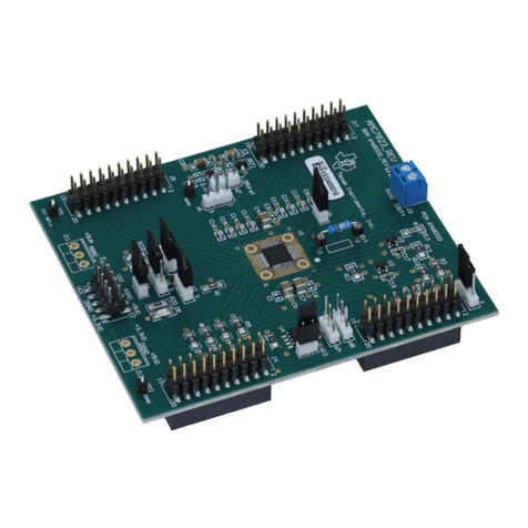
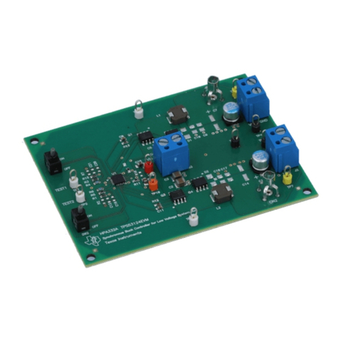
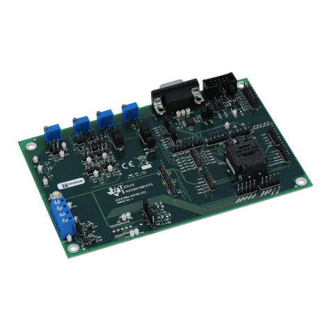
1 DRV2604LEVM-CT Board.................................................................................................. 1
2 Board Diagram............................................................................................................... 4
3 DRV2604LEVM-CT Mode Sets............................................................................................ 5
4 ERM Click and Bounce Waveform (Button 1)............................................................................ 7
5 LRA Ramp-Up and Click Waveform (Button 2).......................................................................... 7
6 ERM Closed-Loop Click Waveform (Button 1)........................................................................... 7
7 ERM Open-Loop Click Waveform (Button 4) ............................................................................ 7
8 LRA Single-Cycle Click (Button 2)......................................................................................... 8
9 LRA Single-Cycle with Braking (Button 3)................................................................................ 8
10 LRA Closed-Loop Click Waveform (Button 1) ........................................................................... 8
11 LRA Open-Loop Click Waveform (Button 4) ............................................................................. 8
12 LRA Auto-Resonance ON Waveform (Button 1) ........................................................................ 9
13 LRA Auto-Resonance OFF Waveform (Button 2)....................................................................... 9
14 Acceleration Versus Frequency............................................................................................ 9
15 LRA Scroll Wheel Effect Waveform (Button 4)......................................................................... 10
16 LRA Click with Braking in Open Loop (Button 3) ...................................................................... 10
17 LRA Click with Braking in Auto Resonance (Button 1)................................................................ 10
18 Power Jumper Selection .................................................................................................. 15
19 Terminal Block and Test Points .......................................................................................... 15
20 External PWM Input........................................................................................................ 16
21 External Trigger Control................................................................................................... 17
22 External I2C Input........................................................................................................... 18
23 Analog Input................................................................................................................. 19
2DRV2604L ERM, LRA Haptic Driver Evaluation Kit SLOU390A–May 2014–Revised June 2014
Submit Documentation Feedback
Copyright © 2014, Texas Instruments Incorporated
