www.ti.com
2SNLU203A–February 2016–Revised September 2019
Submit Documentation Feedback
Copyright © 2016–2019, Texas Instruments Incorporated
DS250DF410EVM User’s Guide
Contents
1 Hardware Description and Setup .......................................................................................... 3
2 Software Description ........................................................................................................ 4
3 Best Practices and Usage Tips........................................................................................... 21
4 Test Case Examples....................................................................................................... 22
5 Supplemental Documents................................................................................................. 22
6 EVM Cable Assemblies ................................................................................................... 23
List of Figures
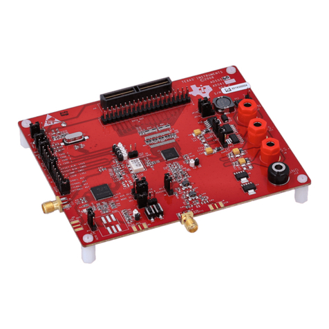
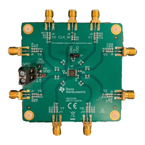
1 DS250DF410EVM, Showing Connections for Power, Signal, and USB Communications ........................ 3
2 Download SigCon Architect from www.ti.com ........................................................................... 4
3 Sigcon Architect Start-Up Screen ......................................................................................... 5
4 Capture Illustrating the “Manage Devices” Pop-Up Window for Adding New Part Numbers to the
“Selection” Panel............................................................................................................. 6
5 Low-Level Page Capture Illustrating the Different Block Select Options............................................. 7
6 Low-Level Page Capture After Selecting Access to an Individual Register.......................................... 7
7 Eye Monitor Page for DS250DF410 Profile.............................................................................. 8
8 EEPROM Page for DS250DF410 Profile................................................................................. 9
9 High-Level Page, with Block Diagram Tab Selected .................................................................. 10
10 High-Level Page, with Device Status Tab Selected................................................................... 11
11 Rx EQ/DFE Tab............................................................................................................ 12
12 Cross-Point Tab, Default Mode Selected ............................................................................... 14
13 Cross-Point Tab, Fanout Mode Selected ............................................................................... 14
14 Cross-Point Tab, Lane Crossing Mode Selected ...................................................................... 15
15 CDR Tab, Standard Mode Selected..................................................................................... 16
16 CDR Tab, Manual Mode Selected....................................................................................... 17
17 TX FIR Tab.................................................................................................................. 18
18 PRBS Tab, PRBS Generator Configuration ............................................................................ 19
19 PRBS Tab, PRBS Checker Configuration .............................................................................. 20
20 SDD21 Loss Characteristic of Example Test Case.................................................................... 22
Trademarks
All trademarks are the property of their respective owners.
