12.2 Download Contents........................................................................................................................................................16
12.3 Installation of the ALP Software..................................................................................................................................... 16
12.4 Startup - First Launch.....................................................................................................................................................17
13 Using ALP and DS90UB954 Profile...................................................................................................................................21
13.1 Information Tab.............................................................................................................................................................. 21
13.2 Registers Tab................................................................................................................................................................. 22
13.3 Registers Tab - Address 0x00 Expanded.......................................................................................................................23
13.3.1 Port Specific Registers............................................................................................................................................ 23
13.4 Saving and Loading Register Settings........................................................................................................................... 23
13.5 Scripting Tab.................................................................................................................................................................. 27
13.5.1 Example Functions.................................................................................................................................................. 29
13.6 GPIO Tab....................................................................................................................................................................... 31
13.7 Forwarding Tab.............................................................................................................................................................. 32
13.8 CSI Registers Tab.......................................................................................................................................................... 33
13.9 Remote Registers Tab....................................................................................................................................................34
14 Troubleshooting ALP Software......................................................................................................................................... 35
14.1 ALP Does Not Detect The EVM..................................................................................................................................... 35
14.2 USB2ANY Firmware Issues........................................................................................................................................... 36
15 DS90UB954-Q1EVM PCB Schematics, Layout and Bill of Materials - DS90UB954-Q1EVM Schematic..................... 38
16 DS90UB954-Q1 EVM PCB Layout..................................................................................................................................... 46
17 DS90UB954-Q1EVM Bill of Materials................................................................................................................................ 56
18 Revision History................................................................................................................................................................. 61
List of Figures
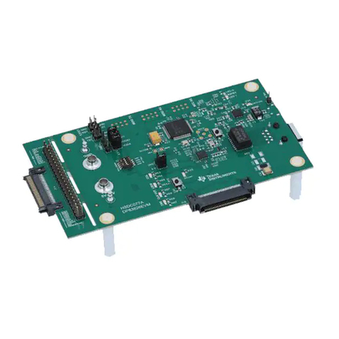
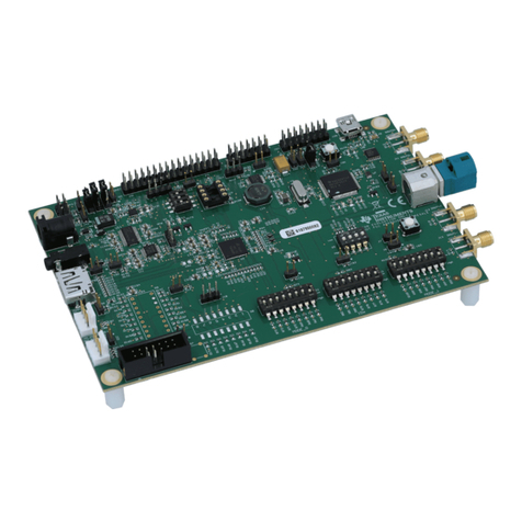
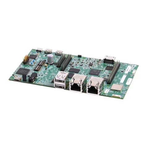
Figure 2-1. DS90UB954-Q1EVM.................................................................................................................................................4
Figure 3-1. Applications Diagram................................................................................................................................................ 5
Figure 3-2. Interfacing to the EVM...............................................................................................................................................6
Figure 4-1. DS90UB954-Q1EVM with Jumpers Highlighted....................................................................................................... 7
Figure 4-2. Power-over-Coax Network For Use With DS90UB953............................................................................................. 8
Figure 4-3. Power-over-Coax Network For Use With DS90UB933............................................................................................. 9
Figure 9-1. Typical Test Setup for Evaluation............................................................................................................................ 14
Figure 12-1. Launching ALP Splash Screen..............................................................................................................................17
Figure 12-2. Initial ALP Screen..................................................................................................................................................17
Figure 12-3. Select USB2ANY/Aardvark Setup to Change Profile............................................................................................ 18
Figure 12-4. ALP Profiles Dialog............................................................................................................................................... 19
Figure 12-5. ALP Profiles Dialog (continued)............................................................................................................................ 20
Figure 13-1. ALP Information Tab..............................................................................................................................................21
Figure 13-2. ALP Registers Tab.................................................................................................................................................22
Figure 13-3. ALP Device ID Expanded......................................................................................................................................23
Figure 13-4. Save Register Settings Step 1.............................................................................................................................. 24
Figure 13-5. Save Register Settings Step 2.............................................................................................................................. 24
Figure 13-6. Save Register Settings Step 3.............................................................................................................................. 25
Figure 13-7. Load Register Settings Step 1...............................................................................................................................25
Figure 13-8. Load Register Settings Step 2...............................................................................................................................26
Figure 13-9. Load Register Settings Step 3...............................................................................................................................26
Figure 13-10. ALP Scripting Tab................................................................................................................................................27
Figure 13-11. Pre-Defined Scripts..............................................................................................................................................28
Figure 13-12. Custom Button Creation Step 1...........................................................................................................................28
Figure 13-13. Custom Button Creation Step 2...........................................................................................................................29
Figure 13-14. GPIO Tab.............................................................................................................................................................31
Figure 13-15. Forwarding Tab....................................................................................................................................................32
Figure 13-16. CSI Registers Tab............................................................................................................................................... 33
Figure 13-17. Remote Registers Tab.........................................................................................................................................34
Figure 14-1. ALP No Devices Error........................................................................................................................................... 35
Figure 14-2. Windows 7, ALP USB2ANY Driver........................................................................................................................35
Figure 14-3. ALP in Demo Mode............................................................................................................................................... 36
Figure 14-4. ALP Preferences Menu......................................................................................................................................... 36
Figure 14-5. USB2ANY Firmware Update Notice......................................................................................................................37
Figure 14-6. USB2ANY Firmware Update Procedure............................................................................................................... 37
Figure 15-1. DS90UB954-Q1EVM Block Diagram.................................................................................................................... 38
Figure 15-2. DS90UB954-Q1EVM Main Circuit - Page 1.......................................................................................................... 39
Figure 15-3. DS90UB954-Q1EVM CSI-2 Connectors - Page 2................................................................................................ 40
Figure 15-4. DS90UB954-Q1EVM PoC Circuits - Page 3......................................................................................................... 41
Table of Contents www.ti.com
2DS90UB954-Q1EVM Deserializer User's Guide SNLU223D – AUGUST 2017 – REVISED FEBRUARY 2023
Submit Document Feedback
Copyright © 2023 Texas Instruments Incorporated
